Gentec SC0501 User manual

SC0501
Compact Scaler Switcher
All Rights Reserved
Version: SC0501_2015V1.8
User Manual

Compact Scaler Switcher (with PoC)
SAFETY PRECAUTIONS
To insure the best from the product, please read all instructions carefully before using
the device. Save this manual for further reference.
Unpack the equipment carefully and save the original box and packing material for
possible future shipment
Follow basic safety precautions to reduce the risk of fire, electrical shock and injury
to persons.
Do not dismantle the housing or modify the module. It may result in electrical shock
or burn.
Using supplies or parts not meeting the products’ specifications may cause
damage, deterioration or malfunction.
Refer all servicing to qualified service personnel.
To prevent fire or shock hazard, do not expose the unit to rain, moisture or install
this product near water.
Do not put any heavy items on the extension cable in case of extrusion.
Do not remove the housing of the device as opening or removing housing may
expose you to dangerous voltage or other hazards.
Install the device in a place with fine ventilation to avoid damage caused by
overheat.
Keep the module away from liquids.
Spillage into the housing may result in fire, electrical shock, or equipment damage.
If an object or liquid falls or spills on to the housing, unplug the module immediately.
Do not twist or pull by force ends of the optical cable. It can cause malfunction.
Do not use liquid or aerosol cleaners to clean this unit. Always unplug the power to
the device before cleaning.
Unplug the power cord when left unused for a long period of time.
Information on disposal for scrapped devices: do not burn or mix with general
household waste, please treat them as normal electrical wastes.

Compact Scaler Switcher (with PoC)
NOTICE:
1. Please read this user manual carefully before using this product.
2. The item PoC is short for Power over Cable, and when the power adapter is
connecting with HDMI Twisted Pair PoC Receiver, Compact Scaler Switcher can’t
be energized through PoC.
3. The receiver works with Compact Scaler Switcher can only be HDMI Twisted Pair
PoC Receiver.
4. The item “far-end” means the device (e.g. display device, 3rd party RS232 device
etc) connected with HDMI Twisted Pair PoC Receiver.
5. Take notice to 4.6 Instructions of VGA Converting Cable when using.
6. Pictures shown in this manual are for reference only, different model and
specifications are subject to real product.
This manual is for operation instruction only, not for any maintenance usage. The
functions described in this version are updated till January 2015. Any changes of
functions and parameters since then will be informed separately. Please refer to
the dealers for the latest details.
All rights reserved. No part of this publication may be copied or reproduced
without the prior written consent.
All product function is valid till 2015-01-12.

Compact Scaler Switcher (with PoC)
Contents
1. Introduction .................................................................................................................1
1.1 Introduction to Compact Scaler Switcher...........................................................1
1.2 Features ............................................................................................................1
1.3 Package Contents .............................................................................................1
2. Product Appearance ...................................................................................................2
2.1 Compact Scaler Switcher Front Panel...............................................................2
2.2 Compact Scaler Switcher Rear Panel ...............................................................4
3. System Connection.....................................................................................................5
3.1 Usage Precautions ............................................................................................5
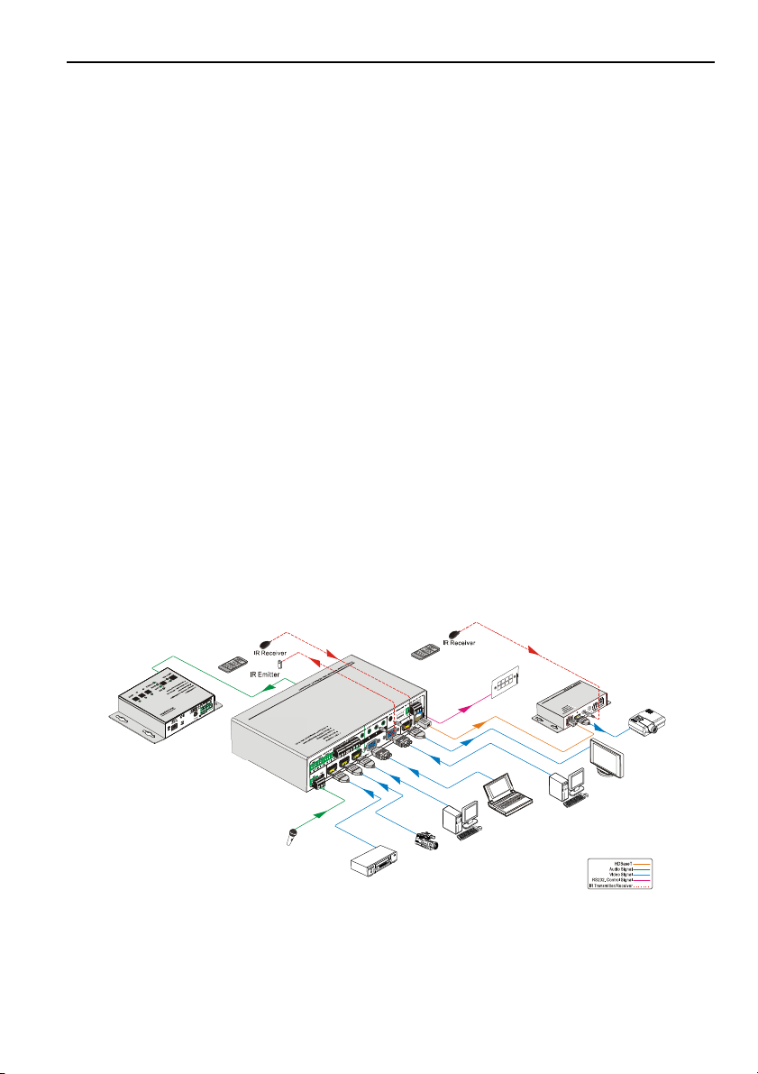
3.2 System Diagram ................................................................................................5
3.3 Connection Procedure.......................................................................................6
3.4 Connection of Microphone.................................................................................6
3.5 Application .........................................................................................................9
4. System Operations .....................................................................................................9
4.1 Operations of Front Panel Buttons ....................................................................9
4.1.1 Resolution Adjusting ................................................................................9
4.1.2 Switching Operations...............................................................................9
4.1.3 Volume Adjusting ...................................................................................10
4.1.4 Used in OSD Menu................................................................................11
4.1.5 Software updating:.................................................................................11
4.2 Operations of IR ..............................................................................................12
4.2.1 IR Remote .............................................................................................12
4.2.2 IR Operations ........................................................................................13
4.3 Operations of CEC Function............................................................................14
4.4 Operations of RS232 Control...........................................................................15
4.4.1 Installation/uninstallation of RS232 Control Software ............................15
4.4.2 Basic Settings........................................................................................15
4.4.3 RS232 Communication Commands ......................................................16
4.4.4 Control Compact Scaler Switcher or 3rd Party Device from Local.........24
4.4.5 Control Compact Scaler Switcher from Local or Remote ......................25
4.5 Operations in OSD Menu.................................................................................26

Compact Scaler Switcher (with PoC)
4.5.1 Option....................................................................................................26
4.5.2 Picture ...................................................................................................28
4.5.3 Sound ....................................................................................................28
4.5.4 Setup .....................................................................................................29
4.6 Instructions of VGA Converting Cable .............................................................30
5. Specification .............................................................................................................31
6. Panel Drawing ..........................................................................................................33
7. Troubleshooting & Maintenance ...............................................................................33
8. After-sales Service....................................................................................................35

Compact Scaler Switcher (with PoC)
1
1. Introduction
1.1 Introduction to Compact Scaler Switcher
Compact Scaler Switcher is a compact mini scaler switcher with 5 video inputs (3
HDMI, 2 VGA) and 6 audio inputs (3 HDMI audio & 2 VGA audio: switched following the
video; 1 MIC audio input). As the VGA input supports VGA, YPbPr and C-video, so the
scaler switcher is compliant with multiple video signals.
Compact Scaler Switcher scales & switches any video signal to HDMI output and
HDBaseT output (supports PoC, connects with HDMI Twisted Pair PoC Receiver, max
transmission distance is 60 meters).
And with 1 IR IN, 5 IR OUT & 1 RS232, IR & RS232 signal can be transmitted bi-
directionally between Compact Scaler Switcher and HDMI Twisted Pair PoC Receiver.
1.2 Features
Compliant with HDCP
Supports CEC, with commands to enable/disable this function
Supports video source auto-switching function
Bi-directional IR & RS232 control
Output resolutions selectable to assure preferred output, and supports various
output resolutions, such as 1920x1200, 1920x1080, 1600x1200, 1360x768,
1280x800, 1280x720, 1024x768
VGA video supports C-video, YPbPr and VGA
Supports online software upgrading
48V phantom power to support condenser microphone
MIC port supports balance/unbalance signal, suppress the external noise effectively
3-level MIC input, supports condenser microphone, dynamic microphone and
wireless microphone
Controllable via button, IR & RS232
Powerful OSD function
1.3 Package Contents
1 x Compact Scaler Switcher
2 x Mounting ears (for Compact Scaler Switcher)
1 x HDMI Twisted Pair PoC Receiver
2 x Mounting ears (for HDMI Twisted Pair PoC Receiver)
5 x Screws (black color)
7 x Captive screw connectors

Compact Scaler Switcher (with PoC)
2
1 x IR receiver (with carrier wave)
1 x IR emitter
2 x VGA to YPbPr cables
2 x RS232 cable
8 x Plastic cushions
1 x IR remote (Cell battery is not included)
1 x Power Adapter (DC 12V)
1 x User Manual
Notes:Please confirm if the product and the accessories are all included, if not,
please contact with the dealers.
2. Product Appearance
2.1 Compact Scaler Switcher Front Panel
①Power indicator
Illuminate red when power on, turn green in standby mode.
②LCD screen
Show real-time system working status
③SOURCE/AUTO
Used as video source selection button, press to select one source, press again
to select next source, switching circularly between HDMI1, HDMI2, HDMI3,
VGA1 and VGA2. The LCD screen will show the name of selected source.
Used as switching mode selection button, press and hold for 7seconds or
more to enter in Auto-switching mode, press and hold for 7seconds or more
again to enter in Manual-switching mode.
Note: Setting any VGA port to AV or YPbPr in Manual-switching mode, the system will
not be able to enter in Auto-switching mode. While in Auto-switching mode, setting any
VGA port to AV or YPbPr will automatically enter in Manual-switching mode, and the
LCD screen and RS232 control software will prompt “Not support!”.

Compact Scaler Switcher (with PoC)
3
④ENTER
Confirm selection in menu.
⑤RESO/AUTO
Used as output resolution manual switching button, select among 1920x1200,
1920x1080, 1600x1200, 1360x768, 1280x800, 1280x720, 1024x768.
Used as output resolution switching mode selection button, press and hold for 7
seconds or more to enter in Auto-switching mode, press and hold for 7
seconds or more again to enter in Manual-switching mode.
⑥MENU/FWUPDATE
Used as menu button, press it to enter in OSD menu.
Used as software updating button, press and hold for 7 seconds or more to
enter in software updating procedure.
⑦VOL-
Used as volume down button.
Used as direction button NEXT in menus.
⑧MIC+
Used as MIC volume up button.
Used as direction button MOVE UP in menus.
⑨VOL+
Used as volume up button.
Used as direction button PREVIOUS in menus.
⑩MIC-
Used as MIC volume down button.
Used as direction button MOVE DOWN in menus.
Note: Pictures shown in this manual are for reference only, different model and
specifications are subject to real product.

Compact Scaler Switcher (with PoC)
4
2.2 Compact Scaler Switcher Rear Panel
①AUDIO INPUT
Including 3 HDMI audio & 2 VGA audio inputs
User can choose any one audio (embedded HDMI audio or external input audio) for
HDMI audio input by sending RS232 commands.
②AUDIO OUTPUT
Audio output port, the audio comes from the input audio corresponding to the
selected video source and mixed with MIC audio.
③IR OUT
5 in total, connect with IR emitters to control local source devices or Compact
Scaler Switcher from remote, switched along with corresponding video source.
④IR IN
Connects with IR receiver (with carrier wave only), to receive IR signal send by the
IR remote or remote controller of other input/output device.
⑤FIRMWARE
USB port, connects with USB flash disk or other storage which is with update file
inside, to update the system firmware.
⑥RS232
Serial control port, 3-pin captive screw connector, connect with a control device
(such as a computer) to control Compact Scaler Switcher or other devices
connected with HDMI Twisted Pair PoC Receiver.
⑦DC 12V
Power port, connect with DC 12V power adapter.
⑧MIC
a) MIC port
Connect with microphone
b) Dial switch
Including 3 levels: 48V phantom power mode (connect with condenser

Compact Scaler Switcher (with PoC)
5
microphone), MIC mode (connect with dynamic microphone) and LINE mode
(connect with wireless microphone or line audio).
⑨VIDEO INPUT
Video input ports, include 3 HDMI inputs & 2 VGA inputs.
VGA ports support YPbPr, C-video and VGA format. Factory default is VGA format.
⑩OUTPUT
c) HDMI local output
d) HDBaseT output, support PoC.
The two ports share the same audio signal, and the audio signal is mixed with MIC
audio and HDMI embedded audio (output audio). If disabling HDMI embedded audio
output, there will be no audio output through these ports.
Note: Pictures shown in this manual are for reference only, different model
and specifications are subject to real product.
3. System Connection
3.1 Usage Precautions
1) System should be installed in a clean environment and has a prop temperature and
humidity.
2) All of the power switches, plugs, sockets and power cords should be insulated and
safe.
3) All devices should be connected before power on.
3.2 System Diagram
DVD
Rs2 32
c ontro l panel
PC
HD TV
DV Camera
PC
Laptop
MIC
Pr oje ctor
Receiver

Compact Scaler Switcher (with PoC)
6
3.3 Connection Procedure
Step1. Connect HDMI source devices (e.g. Blue-ray DVD) to HDMI input ports of
Compact Scaler Switcher with HDMI cable. Connect VGA source devices (e.g.
PC) to VGA input ports of Compact Scaler Switcher with VGA cable.
Step2. Connect audio sources to corresponding AUDIO INPUT ports on Compact
Scaler Switcher with audio cable. The audio of HDMI can be embedded or
external by sending the right command.
Step3. Connect a HDMI display device to HDMI output port of Compact Scaler Switcher
with HDMI cable.
Step4. Connect HDMI Twisted Pair PoC Receiver to HDBaseT output port of Compact
Scaler Switcher with twisted pair.
Step5. Connect speaker, headphone or amplifier to AUDIO OUTPUT port of Compact
Scaler Switcher.
Step6. Connect control device (e.g. PC) to RS232 port of Compact Scaler Switcher or
HDMI Twisted Pair PoC Receiver (bi-directional RS232 control, either end is
available).
Step7. Both Compact Scaler Switcher and HDMI Twisted Pair PoC Receiver have IR IN
and OUT. When one model is connected with IR receiver, the other model
should connect with an IR transmitter.
For example: When “IR IN” of Compact Scaler Switcher connects with an IR
receiver, the IR transmitter must connect to IR OUT of HDMI Twisted Pair PoC
Receiver.
The IR signal can be transmitted bi-directionally between Compact Scaler
Switcher and HDMI Twisted Pair PoC Receiver.
Step8. Select MIC level and connect right microphone to MIC input port. MIC audio will
be transmitted to AUDIO OUTPUT port and mixed with source audio.
Step9. Connect DC12V power adaptor to the power port (HDMI Twisted Pair PoC
Receiver is able to get power from Compact Scaler Switcher with PoC function).
Note: Compact Scaler Switcher supports unidirectional PoC, i.e., If the power adapter
is connecting with Compact Scaler Switcher, HDMI Twisted Pair PoC Receiver can get
power from Compact Scaler Switcher; but when the power adapter is connecting with
HDMI Twisted Pair PoC Receiver, Compact Scaler Switcher can get power from HDMI
Twisted Pair PoC Receiver.
3.4 Connection of Microphone
Compact Scaler Switcher provides with one 3-level microphone input port, to
accommodate different microphone input modes, including 48V phantom power mode,
MIC mode & LINE mode.

Compact Scaler Switcher (with PoC)
7
48V phantom power input
48V phantom power input has a good frequency characteristic, high input impedance
and high sensitivity.
When switching to “48V”, the MIC input will provide a 48V phantom power. This is only
used for condenser microphone.
Connect the microphone in this way: “+” connects to positive, “-” connects to negative
and “ ” to ground.
MIC input
MIC input has a low frequency characteristics, and wide frequency response.
When switch to “MIC”, the microphone input is used for connecting with dynamic
microphone. There are two different connection methods:
1) Unbalanced connection:
“+” and “ ” connect to ground, and “-” connects to signal.
“-” and “ ” connect to ground, and “+” connects to signal.
2) Balanced connection: “+” connects to positive, “-” connects to negative and “ ”
connects to ground.

Compact Scaler Switcher (with PoC)
8
LINE input
LINE input has a low frequency characteristics, and wide frequency response.
When switch to “LINE”, the microphone input is used for connecting with line audio or
wireless microphone output. There are two different connection methods:
1) Unbalanced connection:
“+” and “ ” connect to ground, and “-” connects to signal.
“-” and “ ” connect to ground, and “+” connects to signal.
2) Balanced connection: “+” connects to positive, “-” connects to negative and “ ”
connects to ground.

Compact Scaler Switcher (with PoC)
9
3.5 Application
Compact Scaler Switcher has a good application in various occasions, such as
computer realm, monitoring, conference room, big screen displaying, television
education, command & control center and smart home etc.
4. System Operations
4.1 Operations of Front Panel Buttons
Front panel buttons can be used for output resolution adjusting, switching operations,
software updating, volume adjusting and other operations in menus.
4.1.1 Resolution Adjusting
Resolution supports auto-adjusting and manual-adjusting. Press and hold for
RESO/AUTO button for 7 seconds or more to switch between auto-adjusting/ manual-
adjusting mode.
Note:
1. In auto-adjusting mode, Compact Scaler Switcher will choose the resolution of the
display device at the far-end as the preferred resolution.
If you need to choose the resolution of local HDMI display device:
Cut off the power of Compact Scaler Switcher and disconnect Compact Scaler
Switcher and HDMI Twisted Pair PoC Receiver.
Turn on the power of Compact Scaler Switcher.
Gets the resolution of local HDMI output device.
Connect HDMI Twisted Pair PoC Receiver to Compact Scaler Switcher.
2. In auto-switching mode, front panel button control is not available, but IR and RS232
control are able to switch modes.
4.1.2 Switching Operations
Video signals support auto-switching and manual-switching. Press and hold for
SOURCE/AUTO button for 7 seconds or more to enter in auto-switching/ manual-
switching mode.
The display result is showed as below:
The display result will be showed for 2 seconds.
IN: HDMI1 MANUAL
1280 X 720
IN: HDMI1 AUTO
1280 X 720

Compact Scaler Switcher (with PoC)
10
The auto-switching mode abides by the following principles:
New input principle
Once detecting a new input signal, Compact Scaler Switcher would switch to this
new signal automatically.
Power rebooting principle
Compact Scaler Switcher offers the function to remember the last displayed signal
when rebooting. Once rebooted, Compact Scaler Switcher will automatically enter
auto-switching mode, and then detect all inputs and memorize their connection
status for future rebooting using.
If the last displayed signal is still available, Compact Scaler Switcher will output the
signal. If not, there will be no signal on output devices.
Signal removing principle
Once removing the current display signal, Compact Scaler Switcher will detect all
input signals with priority from INPUT 1 to INPUT 5. It will transfer the signal firstly
detected to be available to output devices.
Notice: Auto-switching function works only when inputting new signal, removing a
signal or power rebooting. With any VGA port set to AV or YPbPr, the system will be not
able to enter in Auto-switching mode.
Operation Examples:
Connect INPUT 2, INPUT 4, and INPUT 5 ports with source devices, select INPUT
4 to outputs.
Press and hold for the front key SOURCE/AUTO for 7 seconds or more to enter in
auto-switching mode.
No signal removing or new input, Compact Scaler Switcher just works in auto-
switching mode, and take no action (Output from INPUT 4)
Connect INPUT 3 with a source device, and then it will choose INPUT 3 to output.
Remove the signal of INPUT 3, Compact Scaler Switcher will detect from INPUT 1
to INPUT 5. And when it detects that input 2 is available, it will choose INPUT 2 to
output.
Cut off the power of Compact Scaler Switcher, then reboot. As Compact Scaler
Switcher is in auto-switching mode, it will choose INPUT 2 to output.
4.1.3 Volume Adjusting
Not in OSD menu, press VOL – to decrease line volume, VOL + to increase.
Not in OSD menu, press MIC – to decrease MIC volume, MIC + to increase.
A
uto
-
switching function

Compact Scaler Switcher (with PoC)
11
4.1.4 Used in OSD Menu
Press MENU button to enter in OSD menu, and use UP, DWON, LEFT, RIGHT button
to navigate, press ENTER button to confirm selection. MENU button also can be used
to exit present menu level by level until exit the OSD menu.
4.1.5 Software updating:
Compact Scaler Switcher supports software updating via USB flash disk.
Procedures:
1) Copy the file “MERGE_51T.bin” to the root directory of a USB flash disk. (Make
sure the file is copied to the root directory for normal use. The “MERGE_51T.bin”
file is provided/ authorized by our engineering department.
2) Plug the USB flash disk to the Compact Scaler Switcher USB port on its front panel.
3) Press the button “MENU” for 7 seconds or more to update the software
automatically.
Or press this button for 1 second to open the OSD menu “Option” Select
“Software Update” to enter in update procedure.
Or send command 50689% to update software.

Compact Scaler Switcher (with PoC)
12
4.2 Operations of IR
4.2.1 IR Remote
As IR signal can be transmitted bi-directionally between Compact Scaler Switcher and
HDMI Twisted Pair PoC Receiver, it is able to use the IR remote at the far-end to
control Compact Scaler Switcher or HDMI source devices (via CEC function buttons).
①Standby button
Enter/ exit standby mode
②Input channel selection buttons
INPUT 1 is for HDMI1, INPUT 2 for
HDMI2…INPUT 5 for VGA2.
AUTO: Enable/disable auto-switching mode.
③Volume adjusting buttons
MIC-/+: turn down/ up MIC volume
LINE-/+: turn down/ up line volume
MIC MUTE: mute/ unmute MIC audio
LINE MUTE: mute/ unmute line audio
④Menu operation buttons
MENU: press to enter in OSD menu or used to
return to previous menu. EXIT: exit OSD menu.
OK: confirm button. Navigation buttons:
UP/DWON/LEFT/ RIGHT button, for value setting
or page-turn, Buttons in area a are also able to
work in CEC mode to enter the menu of HDMI
source device. P.P, ZOOM, S.M: shortcut button,
to select display mode.
⑤Resolution selection buttons
Select resolution by pressing corresponding
button.
AUTO: Enable/disable auto-switching mode.
⑥CEC function buttons
(For HDMI input signal which supports CEC only)
Including PLAY, PAUSE, STOP, MENU, REV
(reverse) and FWD (forward)
Buttons in section aalso work when entered CEC.
too.

Compact Scaler Switcher (with PoC)
13
4.2.2 IR Operations
The 5 IR OUT ports correspond to the 5 video inputs separately, and the IR signals are
switched following the corresponding video source.
1) Control far-end device from local
Control Compact Scaler Switcher or far-end display device from local through
corresponding IR remote.
2) Control local device from remote
Control Compact Scaler Switcher or local device from local through corresponding IR
remote.

Compact Scaler Switcher (with PoC)
14
4.3 Operations of CEC Function
Compact Scaler Switcher supports CEC, it can be turned on/ off by sending RS232
commands or OSD menu operations. The default setting is ON.
Commands pertaining to CEC: “50686%” (enable CEC) and “50687%” (disable CEC)
HDMI INPUT ports 1~3 support CEC, if the connected source devices also support
CEC and their CEC are on, users can control the source device via the IR remote of
Compact Scaler Switcher.
The working status related to CEC and STANDBY is showed as below:
Situation Working Status
CEC: on, Standby: on
Press STANDBY button on IR remote, Compact Scaler
Switcher enters in standby mode, so do all HDMI source
devices.
Press STANDBY button again on IR remote, Compact
Scaler Switcher exits standby mode, the HDMI source
devices start working too.
CEC: on, Standby: off
Press STANDBY button on IR remote, Compact Scaler
Switcher enters in standby mode, HDMI 1~3 source
devices keep on.
CEC: on
Use CEC function buttons, ▲,▼, , and OK buttons
on IR remote to control HDMI source devices, include play,
pause, fast forward, fast reverse and operations in menu.
CEC: off Unable to control HDMI source devices through IR remote

Compact Scaler Switcher (with PoC)
15
CEC: Control HDMI source devices by IR remote of Compact Scaler Switcher
4.4 Operations of RS232 Control
As RS232 can be transmitted bi-directionally between Compact Scaler Switcher and
HDMI Twisted Pair PoC Receiver, so it is able to control a third party RS232 device
from local or control Compact Scaler Switcher from remote. When to control a third
party RS232 device, the baud rate of this device should be 2400, 4800, 9600, 19200,
38400, 57600 or 115200.
4.4.1 Installation/uninstallation of RS232 Control Software
Installation Copy the control software file to the computer connected with Compact
Scaler Switcher.
Uninstallation Delete all the control software files in corresponding file path.
4.4.2 Basic Settings
First to connect Compact Scaler Switcher with all input devices and output devices
needed, then to connect it with a computer which is installed with RS232 control
software. Double-click the software icon to run this software.
Here we take the software CommWatch.exe as example. The icon is showed as
below:
O
K
Z
O
O
M
S
.
M
M
E
N
U
E
X
I
T
I
N
P
U
T
1
P
.
M
1
0
8
0
P
7
2
0
P
M
E
N
U
I
N
P
U
T
5
I
N
P
U
T
2
I
N
P
U
T
3
I
N
P
U
T
4
A
U
T
O
S
c
a
l
e
r
S
w
it
c
h
e
r
A
U
T
O
P
L
A
Y
/
P
A
U
S
E
S
T
O
P
R
E
V
F
W
D
I
N
P
U
T
S
O
U
R
C
E
C
E
C
C
O
N
T
R
O
L
M
I
C
M
U
T
E
M
IC
L
IN
E
L
I
N
E
M
U
T
E
Table of contents
Other Gentec Switch manuals
Popular Switch manuals by other brands

StarTech.com
StarTech.com SV163DI supplementary guide

CTS
CTS FOS-3128 Series user manual

United Integrated Services
United Integrated Services WPW-220 installation instructions

3Com
3Com OfficeConnect 3C1670500A installation guide

Kramer
Kramer VP-690 user manual

SIIG
SIIG Hi-Speed USB 4-Port Bay Hub Quick installation guide