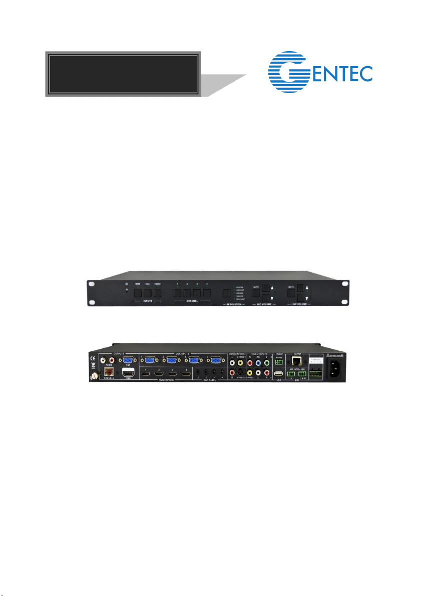
Scaler Switcher with Digital Amplifier-TN (12 inputs)
Contents
1. Introduction .................................................................................................................1
1.1. Introduction to Scaler Switcher with Digital Amplifier-TN ..................................1
1.2. Features ...........................................................................................................1
1.3. Package Contents ............................................................................................1
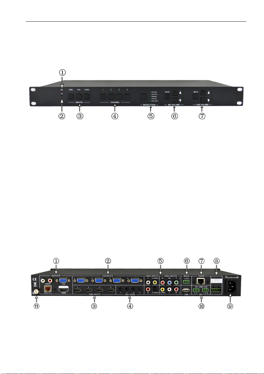
2. Panel Description........................................................................................................2
2.1. Front Panel .......................................................................................................2
2.2. Rear Panel........................................................................................................2
3. System Connection.....................................................................................................3
3.1. Usage Precautions ...........................................................................................3
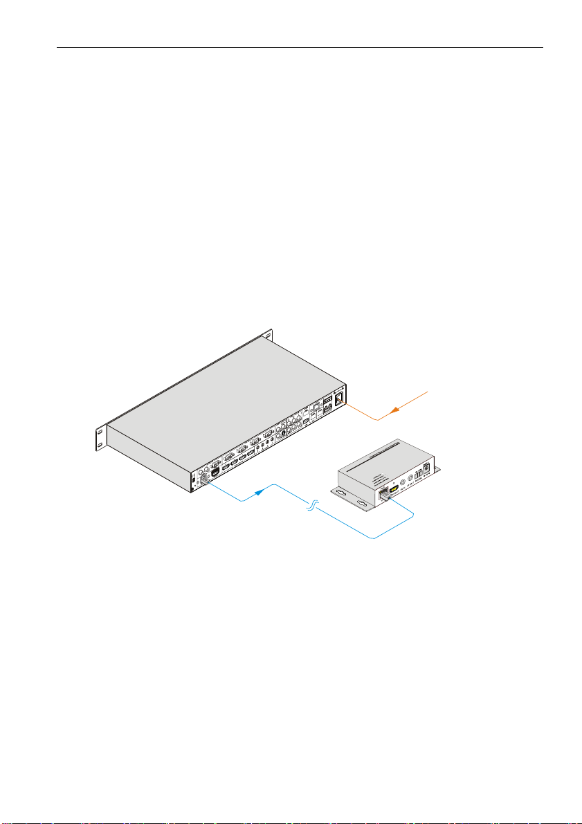
3.2. System Diagram ...............................................................................................3
3.3. Connection Procedures ....................................................................................4
3.4. PoC Solution.....................................................................................................5
3.5. Applications ......................................................................................................6
3.6. Collocation Products.........................................................................................6
4. Operations ..................................................................................................................7
4.1. Operations of the IR Remote ............................................................................7
4.2. OSD Operations ...............................................................................................8
4.2.1. Picture Setting ........................................................................................8
4.2.2. Audio Setting ..........................................................................................9
4.2.3. System Setting .....................................................................................10
4.3. Firmware Update ............................................................................................10
4.4. RS232 Control ................................................................................................ 11
4.4.1. Installation/uninstallation of RS232 Control Software ........................... 11
4.4.2. Basic Settings....................................................................................... 11
4.4.3. RS232 Commands ...............................................................................12
4.4.4. Control Modes ......................................................................................15
4.4.5. Control Scaler Switcher with Digital Amplifier-TN via TCP/IP
communication software.................................................................................16
4.4.6. TCP/IP Configuration............................................................................17
5. Specification .............................................................................................................18
5.1. Specifications of Scaler Switcher with Digital Amplifier-TN.............................18
5.2. Specifications of Video/Audio Input/output .....................................................19
5.2.1. C-Video and S-Video input ...................................................................19
5.2.2. YPbPr input ..........................................................................................20
5.2.3. VGA input .............................................................................................20
5.2.4. HDMI input............................................................................................20