Gentner XAP TH2 User manual

Perfect Communication through Technology, Service, and Education.
®
Installation & Operation Manual
Telephone Interface
XAP TH2

TECHNICAL SUPPORT: 1.800.283.5936 (USA) OR 1.801.974.3760
XAP TH2 Telephone Inter ace Installation and Operation Manual
Gentner Part No. 800-151-301
Revision 1.1
©2001 Gentner Communications Corporation. All rights reserved. No part of this manual may be reproduced in any
form or by any means without written permission from Gentner Communications Corporation. rinted in the United
States of America. Gentner Communications Corporation reserves specification privileges. Information in this
manual is subject to change without notice.

TECHNICAL SUPPORT: 1.800.283.5936 (USA) OR 1.801.974.3760
iii
able of Contents
T
Introduction . . . . . . . . . . . . . . . . . . . . . . . . . . . . .1
Congratulations . . . . . . . . . . . . . . . . . . . . . . . . . . . . . . . . . . . . . . . . . . . . . . . . . . . . . . .1
roduct Registration . . . . . . . . . . . . . . . . . . . . . . . . . . . . . . . . . . . . . . . . . . . . . . . . . .2
Technical Services . . . . . . . . . . . . . . . . . . . . . . . . . . . . . . . . . . . . . . . . . . . . . . . . . . . .2
Features . . . . . . . . . . . . . . . . . . . . . . . . . . . . . . . . . . . . . . . . . . . . . . . . . . . . . . . . . . . . . .3
Unpacking . . . . . . . . . . . . . . . . . . . . . . . . . . . . . . . . . . . . . . . . . . . . . . . . . . . . . . . . . . . .3
Controls and Connections . . . . . . . . . . . . . . . . . . . . . . . . . . . . . . . . . . . . . . . . . . . . .4
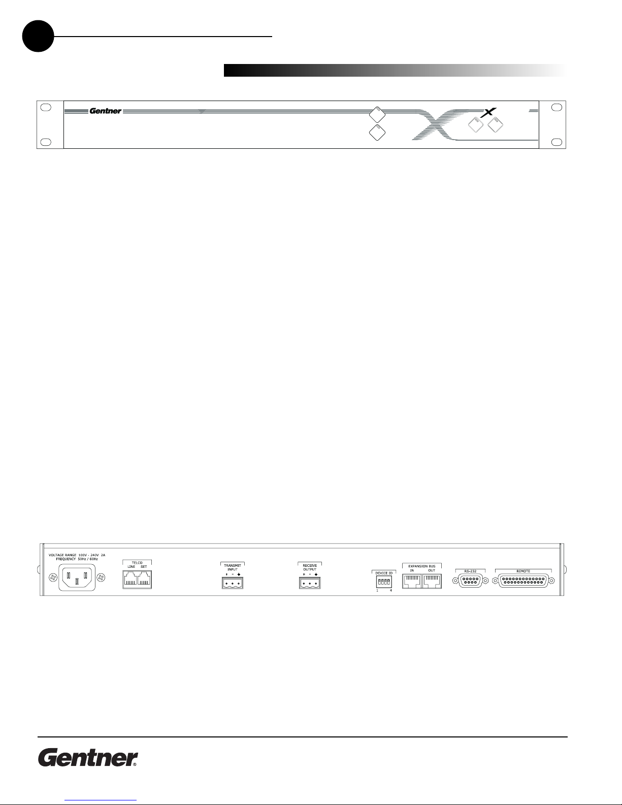
Front View . . . . . . . . . . . . . . . . . . . . . . . . . . . . . . . . . . . . . . . . . . . . . . . . . . . . . . . .4
Rear View . . . . . . . . . . . . . . . . . . . . . . . . . . . . . . . . . . . . . . . . . . . . . . . . . . . . . . . .4
Before You Install . . . . . . . . . . . . . . . . . . . . . . . . . . . . . . . . . . . . . . . . . . . . . . . . . . . . .6
ower Requirements . . . . . . . . . . . . . . . . . . . . . . . . . . . . . . . . . . . . . . . . . . . . .6
Installation . . . . . . . . . . . . . . . . . . . . . . . . . . . . .7
Overview . . . . . . . . . . . . . . . . . . . . . . . . . . . . . . . . . . . . . . . . . . . . . . . . . . . . . . . . . . . . .7
Hardware Setup . . . . . . . . . . . . . . . . . . . . . . . . . . . . . . . . . . . . . . . . . . . . . . . . . . . . . .8
Connect the Unit . . . . . . . . . . . . . . . . . . . . . . . . . . . . . . . . . . . . . . . . . . . . . . . . . .8
Assign Device ID Numbers . . . . . . . . . . . . . . . . . . . . . . . . . . . . . . . . . . . . . . . .9
Create an Expansion Bus Network . . . . . . . . . . . . . . . . . . . . . . . . . . . . . . . . .10
Con iguration . . . . . . . . . . . . . . . . . . . . . . . . . . . .11
Adding a XA TH2 . . . . . . . . . . . . . . . . . . . . . . . . . . . . . . . . . . . . . . . . . . . . . . . . . . . .11
To Add XA TH2 to a Site File . . . . . . . . . . . . . . . . . . . . . . . . . . . . . . . . . . . . .11
To Configure Unit roperties . . . . . . . . . . . . . . . . . . . . . . . . . . . . . . . . . . . . . .12
XA TH2 Flow Screen . . . . . . . . . . . . . . . . . . . . . . . . . . . . . . . . . . . . . . . . . . . . .13
Configuring the XA TH2 . . . . . . . . . . . . . . . . . . . . . . . . . . . . . . . . . . . . . . . . . . . . . .13
Creating Custom Control . . . . . . . . . . . . . . . . . . . . . . . . . . . . . . . . . . . . . . . . . . . . . .15
To Use G IO Builder . . . . . . . . . . . . . . . . . . . . . . . . . . . . . . . . . . . . . . . . . . . . . .15
Synchronize Site File to the XA TH2 . . . . . . . . . . . . . . . . . . . . . . . . . . . . . . . . . . .16
To Sync Site File to the XA TH2 . . . . . . . . . . . . . . . . . . . . . . . . . . . . . . . . . . .16
To Answer a Call . . . . . . . . . . . . . . . . . . . . . . . . . . . . . . . . . . . . . . . . . . . . . . . . . .17
Operation . . . . . . . . . . . . . . . . . . . . . . . . . . . . . . .17
Using the XA TH2 . . . . . . . . . . . . . . . . . . . . . . . . . . . . . . . . . . . . . . . . . . . . . . . . . . . .17
To Make and Disconnect a Call . . . . . . . . . . . . . . . . . . . . . . . . . . . . . . . . . . .18
Using the Dial Interface . . . . . . . . . . . . . . . . . . . . . . . . . . . . . . . . . . . . . . . . . . . . . . .18
To Make and Disconnect a Call . . . . . . . . . . . . . . . . . . . . . . . . . . . . . . . . . . . .18
To Dial Multiple Numbers . . . . . . . . . . . . . . . . . . . . . . . . . . . . . . . . . . . . . . . . .18
To Mute . . . . . . . . . . . . . . . . . . . . . . . . . . . . . . . . . . . . . . . . . . . . . . . . . . . . . . . . . .19

TECHNICAL SUPPORT: 1.800.283.5936 (USA) OR 1.801.974.3760
iv
Custom Control (DB25) Option . . . . . . . . . . . . . . . . . . . . . . . . . . . . . . . . . . . .20
External Control System . . . . . . . . . . . . . . . . . . . . . . . . . . . . . . . . . . . . . . . . . . .20
Touch-Tone Dialing . . . . . . . . . . . . . . . . . . . . . . . . . . . . . . . . . . . . . . . . . . . . . . .20
Controllers . . . . . . . . . . . . . . . . . . . . . . . . . . . . . . . . . . . . . . . . . . . . . . . . . . . . . . . . . . . .20
Optimization . . . . . . . . . . . . . . . . . . . . . . . . . . . . .21
Adjusting Levels . . . . . . . . . . . . . . . . . . . . . . . . . . . . . . . . . . . . . . . . . . . . . . . . . . . . . .21
Adjusting Transmit Audio . . . . . . . . . . . . . . . . . . . . . . . . . . . . . . . . . . . . . . . . . .22
Adjusting DTMF Level . . . . . . . . . . . . . . . . . . . . . . . . . . . . . . . . . . . . . . . . . . . . .22
Adjusting Dial Tone Level . . . . . . . . . . . . . . . . . . . . . . . . . . . . . . . . . . . . . . . . .22
Audible Hook Indication . . . . . . . . . . . . . . . . . . . . . . . . . . . . . . . . . . . . . . . . . .22
Audible Ringer Indication . . . . . . . . . . . . . . . . . . . . . . . . . . . . . . . . . . . . . . . . .22
Telco Meters . . . . . . . . . . . . . . . . . . . . . . . . . . . . . . . . . . . . . . . . . . . . . . . . . . . . . . . . . .23
Using Meters . . . . . . . . . . . . . . . . . . . . . . . . . . . . . . . . . . . . . . . . . . . . . . . . . . . . .23
Appendices . . . . . . . . . . . . . . . . . . . . . . . . . . . . .25
Appendix A: Specifications . . . . . . . . . . . . . . . . . . . . . . . . . . . . . . . . . . . . . . . . . . . .25
Appendix B: Connector inouts . . . . . . . . . . . . . . . . . . . . . . . . . . . . . . . . . . . . . . . .27
Appendix C: Serial Commands . . . . . . . . . . . . . . . . . . . . . . . . . . . . . . . . . . . . . . . .29
Appendix D: Warranty and Compliance . . . . . . . . . . . . . . . . . . . . . . . . . . . . . . . .54
Appendix E: Block Diagram . . . . . . . . . . . . . . . . . . . . . . . . . . . . . . . . . . . . . . . . . . . .60
Glossary . . . . . . . . . . . . . . . . . . . . . . . . . . . . . . . .61
Index . . . . . . . . . . . . . . . . . . . . . . . . . . . . . . . . . . .63

TECHNICAL SUPPORT: 1.800.283.5936 (USA) OR 1.801.974.3760
1
Introduction
Congratulations
INTRODUCTION • 1
Congratulations on purchasing the XA TH2 telephone interface. The
XA TH2 is a single-line digital hybrid which uses digital signal
processing (DS ) to separate the transmit and receive audio,
eliminating distortion, weak signals, and feedback. It continually filters
low and high frequency noise to provide pure sound.
The XA TH2 is designed to function as a standalone telephone hybrid
or as an accessory to the XA 800 (echo cancelling, audio processing,
microphone mixing matrix), enabling you to add remote callers to your
audioconferences.
This manual explains how to install, configure, and operate the XA TH2
in a step-by-step format.

TECHNICAL SUPPORT: 1.800.283.5936 (USA) OR 1.801.974.3760
2INTRODUCTION • TECHNICAL SU ORT
If you need any additional information on how to install, set up or
operate your system, please contact us at one of the locations listed
below. We welcome and encourage your comments so we can
continue to improve our products and serve your needs.
Gentner Communications Corporation
1825 Research Way, Salt Lake City, UT 84119
Telephone: 1.800.283.5936(USA) or 1.801.974.3760
Fax: 1.801.977.0087
E-mail: tech2@gentner.com
Web site: www.gentner.com
Sales and Customer Service
Telephone: 1.800.945.7730 (USA) or 1.801.975.7200
Fax: 1.800.933.5107 (USA) or 1.801.977.0087
E-mail: products@gentner.com
Gentner Communications EuMEA GmbH
Leonhardstr. 16-18, D-90443 Nuremberg, Germany
Telephone: +49 911 955159-0
Fax: +49 911 955159-10
E-mail: sales@gentner.com
Technical
Services
Product
Registration lease register your XA TH2 online by visiting Gentner Technical Support
at www.gentner.com. When your product is properly registered, Gentner
Communications is better able to serve you should you require technical
assistance. Registration information is also used to notify you of upgrades
and new product information.

TECHNICAL SUPPORT: 1.800.283.5936 (USA) OR 1.801.974.3760
3
INTRODUCTION • UN ACKING
Ensure that the following items (See Figure 1, below) were received with
your shipment:
Unpacking
Gentner Comm nications
is not responsible for prod-
ct damage inc rred d r-
ing shipment. Yo m st make
claims directly with the carrier.
Inspect yo r shipment caref lly for
obvio s signs of damage. If the
shipment appears to be damaged,
retain the original boxes and pack-
ing material for inspection by the
carrier. Contact yo r carrier imme-
diately.
!
Transmit
Receive
2
PAHT
On Off
Features
Gentner’s 100% digital signal processing (DS ) technology ensures
crystal-clear audio with the deepest, most reliable hybrid null.
Balanced line-level input and output
Touch-tone dialing capability (40 character dial string)
Full-time telco echo cancellation with 31 millisecond tail time
Conference up to 16 callers (with 16 XA TH2s) within a XA 800
system
Adjustable audible connect and disconnect tones
Selectable caller automatic level control (ALC)
Adjustable dial tone, DTMF attenuation
Simultaneous two-wire/four-wire operation
Continual adaptation to telephone line conditions
Digital anti-alias filter to minimize hum and Central Office switching
noise
Compatible with analog telephone lines
rogram and operate with a connected C or any other type of
serial remote control device via Expansion Bus or RS-232 port

Transmit
Receive
2
PAHT
On Off
TECHNICAL SUPPORT: 1.800.283.5936 (USA) OR 1.801.974.3760
4INTRODUCTION • CONTROLS AND CONNECTIONS
Front View
The XA TH2 front-panel controls perform the following functions:
1. Transmit LED This bicolor LED indicates the audio levels being
transmitted from the room to the telephone line.
2. Receive LED This bicolor LED indicates the audio level the room is
receiving from the telephone line.
3. On LED This bicolor LED indicates the hybrid’s ON state. The LED
will illuminate green when the hybrid is in the ON state.
4. Off LED This bicolor LED indicates the hybrid’s OFF state. The LED
will illuminate red when the hybrid is in the OFF state.
5. On The ON button connects the XA TH2 to the telephone line and
automatically adapts the hybrid to the line. ressing and holding the
ON button for more than a half-second while the hybrid is active will
readapt the hybrid. When the hybrid is activated from the OFF to ON
state, the XA TH2 will send the updated status via the Expansion
Bus.
6. Off The OFF switch disconnects the hybrid from the telephone line
and mutes all audio.
Rear View
The XA TH2 back-panel connectors perform the following functions:
1. Power The AC power cord input is a NEMA type connector allowing
100–240VAC, 50/60Hz.
Controls and
Connections
XAP TH2 front-pan l controls
XAP TH2 back-pan l conn ctors

TECHNICAL SUPPORT: 1.800.283.5936 (USA) OR 1.801.974.3760
5
INTRODUCTION • CONTROLS AND CONNECTIONS
2. Telco Line This RJ-11 connector provides connection of a standard
analog telephone line to the hybrid.
3. Telco Set This RJ-11 connector allows connection to a standard
telephone set. Tip and ring from the phone line are present at this
connector when the hybrid is in its off state. Tip and ring from the
phone line are not present at this point when the hybrid is in its on
state.
4. Transmit Inp t This hoenix connection provides a non-gated
electronically balanced line level input. The nominal input level is 0
dBu. This line input is mutable. The default setting is off (not muted).
5. Receive O tp t This hoenix connection provides a balanced line
level output. The nominal output level is 0 dBu. The output adjusts
for line imbalances and maintains a constant output level. This line
output is mutable. The default setting is off (not muted).
6. Device ID This four-position DI Switch is used to assign a device ID
number to the XA TH2. See page 9 for more details.
7. Expansion B s In, O t This RJ-45 connector is used to connect
the XA TH2 to the XA 800 for control. G-Ware is capable of
accessing an controlling an Expansion Bus local area network (LAN)
of up to eight XA 800/ SR1212 units and 16 XA TH2 units, where
the total number of microphone inputs does not exceed 64. The
Expansion Bus supports a distance of up to 80 feet between each
connected XA 800 or SR1212.
8. RS-232 This female DB9 serial port is for interconnection between
the XA TH2 and a C, modem, or other custom remote controller.
For serial protocol, see 29.
9. Remote This DB25 connector provides control and status of the
XA TH2 and unbalanced audio. See Appendix B for pinouts.

TECHNICAL SUPPORT: 1.800.283.5936 (USA) OR 1.801.974.3760
6INTRODUCTION • BEFORE YOU INSTALL
Power Requirements
The XA TH2 automatically accommodates voltage requirements of
100–240VAC, 50/60Hz, 15W.
Telephone Line Requirements
The XA TH2 model operates on a standard analog telephone line and
connects to the telephone system with a standard RJ-11C modular jack.
If you do not have an RJ-11C jack where you want to install your
XA TH2, call your telephone company for installation.
The XA TH2 can be configured to meet compliance requirements of
different countries via the G-Ware software. See page 12.
Equipment Placement
The XA TH2 models are designed for installation in a standard 19-inch
equipment rack. You can also purchase side panels for desktop
placement.
Network Requirements
The Expansion Bus (RS-485 LAN) lets you connect up to eight XA 800s
and 16 XA TH2 units, where the total number of microphone inputs
does not exceed 64. The maximum distance between interconnected
XA 800 or SR1212 units is 80 feet (24 meters). Gentner recommends
that category five twisted-pair (10BaseT LAN) cable be used.
Environmental Requirements
The XA TH2 can be safely operated in a room with varying
temperatures between 32 °F (0 °C) and 110 °F (43 °C).
Be ore You
Install
Warning: The co ntry code
m st be set correctly in
G-Ware to ens re that the
nit operates properly when con-
nected to the telco network and
complies with the co ntry’s telco
req irements. Changing this code
to a co ntry other than the intended
co ntry of operation might ca se
the XAP TH2 to be
non-compliant.
!

TECHNICAL SUPPORT: 1.800.283.5936 (USA) OR 1.801.974.3760
2
The XA TH2 is designed for easy installation and setup. All
connections are made through rear-panel connectors. This section
provides instructions on installing the units in the rack and making initial
connections, assigning device ID numbers, and creating an Expansion
Bus (E-Bus) network.
The diagram below illustrates the typical connections that are made
when adding a XA TH2 to a XA 800.
Installation
Overview
INSTALLATION • OVERVIEW 7
EscEnter Meter
+8
+8
+4
+4
0
0
-4
-4
-10
-10
-30
-30
1
2
3
4
5
6
7
8
Mic On
+12
Syst m diagram

TECHNICAL SUPPORT: 1.800.283.5936 (USA) OR 1.801.974.3760
8INSTALLATION • HARDWARE SETU
Connect the Unit
Refer to XA TH2 back-panel drawing below. Each connector is
numbered for easy identification.
1. lace the unit in the rack and attach it securely. XA TH2 models
are designed for installation in a standard 19-inch equipment rack.
2. Connect your telephone line from the wall jack to the RJ-11C Line
jack [2].
3. lug your telephone set into the RJ-11C Set jack [2].
4. If you are using a custom controller for control and hybrid status,
plug it into the DB25 Remote connector [8].
If you are using an external RS-232 controller, connect it to the RS-
232 port [7].
5. Wire the XA TH2 to the XA 800 using the provided three-terminal
hoenix push-on connectors. These connectors are designed for
easy wiring; simply insert the desired wire into the appropriate
connector opening and tighten down the top screw.
Transmit Inp t Audio connected to the Transmit Input [3] will
be sent down the telephone line.
Receive O tp t Audio from the telephone participant is
passed to Receive Output [4].
12 3 456 7 8
Pho nix push-on conn ctor
XAP TH2 back-pan l conn ctors
+–
Ground
N gativ
Positiv
The three terminals in the
Phoenix connector corre-
spond with the back-panel
a dio contacts (from left to right):
+(positive), –(negative), and
(gro nd).
✍
Hardware Setup

If more than one XAP TH2
is assigned the same
device ID n mber, the
Transmit and Receive LEDs will
flash red and green on the affected
nits ntil the error is corrected.
!
TECHNICAL SUPPORT: 1.800.283.5936 (USA) OR 1.801.974.3760
INSTALLATION • HARDWARE SETU 9
Assign Device ID Numbers
Before creating an Expansion Bus network, you need to set up unique
Expansion Bus Device ID numbers for each XA TH2 on the network.
There are 16 Expansion Bus network device locations that can be
selected (0-F). As shipped from the factory, all XA TH2 units default as
binary address 0.
Set Device ID numbers for each XA TH2 unit at your site by
manipulating rear-panel DI switches 1–4 [5], selecting/deselecting
each switch to set up address 0–15 in binary code. The table below
illustrates DI switch settings. DI switch changes are only read when
the unit is powered up so you will need to power cycle the unit to have
the changes recognized.
Device ID DIP Switch Settings
Binary DIP Switch 1 DIP Switch 2 DIP Switch 3 DIP Switch 4
Address Position Position Position Position
0 (d fault) 0 (UP) 0 (UP) 0 (UP) 0 (UP)
1 0 (UP) 0 (UP) 0 (UP) 1 ( DOWN)
2 0 (UP) 0 (UP) 1 ( DOWN) 0 (UP)
3 0 (UP) 0 (UP) 1 ( DOWN) 1 ( DOWN)
4 0 (UP) 1 ( DOWN) 0 (UP) 0 (UP)
5 0 (UP) 1 ( DOWN) 0 (UP) 1 ( DOWN)
6 0 (UP) 1 ( DOWN) 1 ( DOWN) 0 (UP)
7 0 (UP) 1 ( DOWN) 1 ( DOWN) 1 ( DOWN)
8 1 (DOWN) 0 (UP) 0 (UP) 0 (UP)
9 1 ( DOWN) 0 (UP) 0 (UP) 1 ( DOWN)
10 (A) 1 (DOWN 0 (UP) 1 ( DOWN) 0 (UP)
11 (B) 1 ( DOWN) 0 (UP) 1 ( DOWN) 1 ( DOWN)
12 (C) 1 ( DOWN) 1 ( DOWN) 0 (UP) 0 (UP)
13 (D) 1 ( DOWN) 1 ( DOWN) 0 (UP) 1 ( DOWN)
14 (E) 1 ( DOWN) 1 ( DOWN) 1 ( DOWN) 0 (UP)
15 (F) 1 ( DOWN) 1 ( DOWN) 1 ( DOWN) 1 (DOWN)

TECHNICAL SUPPORT: 1.800.283.5936 (USA) OR 1.801.974.3760
INSTALLATION • HARDWARE SETU
10
Create an Expansion Bus Network
1. lace the XA TH2 unit in the rack. The back-panel Expansion Bus
In and Expansion Bus Out connectors are designed for setting
up your Expansion Bus network. Connections between units are
made in daisy-chain fashion using category five twisted-pair cable.
2. The first XA unit in the chain must have the Expansion Bus In
connector terminated with an Expansion Bus terminator (provided).
3. The first XA unit’s Expansion Bus Out connector is then attached
to the Expansion Bus In connector on the next unit in the chain. At
the end of the network, the final unit must have the Expansion Bus
Out connector terminated with an Expansion Bus terminator as well.
An Expansion Bus network will allow interconnection of up to16
XA TH2s and any combination of XA 800s and SR1212s where the
number of microphone inputs does not exceed 64.
Connecting Power
The power input [1] will operate at any level between 100–240VAC,
50–60Hz, 15W (typical). lug in the XA TH2 to complete the hardware
installation.
If networked XAP 800s and
TH2s are stacked vertically,
connect them sing the
short RJ-45 j mper. When network-
ing between long distances, se
category five twisted-pair (10BaseT
LAN) cable. The maxim m cable
r n between XAP 800 and PSR1212
nits is 80 feet (24 meters).
✍
Expansion Bus
Terminator
Expansion Bus
Terminator
XAP 800 XAP TH2
XAP TH2
Out
In
Expansion Bus
0A P 8 0

TECHNICAL SUPPORT: 1.800.283.5936 (USA) OR 1.801.974.3760
3
Gentner’s G-Ware software provides an easy interface for configuring
and controlling your XA TH2. This chapter assumes you have already
installed G-Ware and have created a site. If you need help installing
G-Ware, creating a new site, or would like to see system requirements,
consult the XA 800 manual or help file.
To Add XAP TH2 to a Site File
You can add XA TH2(s) to your site file by connecting to your
networked site and letting G-Ware automatically create icons for the
detected units or you can work offline and manually add the unit(s) to
the site file and connect to the site at later time.
1. Open G-Ware software from the Start menu, or by by double-
clicking the desktop icon, and select the site to which you will be
adding the XA TH2.
2. Click the Connect button on the G-Ware taskbar or select Connect
from the Connect Menu. Choose to sync to Unit(s). G-Ware will
automatically create icons for any new units it detects on the
network and place them in the Site pane. Right-click the unit icon
and select Unit roperties.
If you are working offline, click the Add button on the G-Ware
toolbar and select XAP TH2. The XA TH2 Unit roperties window
will open.
Configuration
Adding a XAP TH2
CONFIGURATION • ADDING A XA TH2 11
Unit Icons in Site Pane with Unit Men Showing
When connecting to yo r
site, yo can choose to
sync to Unit(s) or Doc ment.
If yo sync to the Unit(s), yo will
pdate yo r G-Ware site file with the
c rrent state of the nit(s). If yo
sync to the Doc ment, yo will
pdate yo r nits with the settings
yo have saved in the site file.
✍

TECHNICAL SUPPORT: 1.800.283.5936 (USA) OR 1.801.974.3760
CONFIGURING G-WARE • ADDING A XA TH2
12
To Con igure Unit Properties
1. Type a descriptive Unit Name in the space provided. The Unit
Identification and Firmware Version will be supplied by the unit
when a connection is made.
2. If you have already establish a connection with the site, the Device
ID will be assigned. If you are working offline, select the Device ID
that matches the ID you assigned the unit via the back-panel DI
switches. Device IDs ensure the software will sync up with the
proper unit when there are multiple TH2s on a network.
3. Adjust the Meter Refresh rate as necessary. The default rate is 50.
4. Select the country where this product is being used from the
Co ntry Code list.
Warning: The co ntry code m st be set correctly to ens re that
the nit operates properly when connected to the telco network
and complies with the co ntry’s telco req irements. Changing
this code to a co ntry other than the intended co ntry of
operation might ca se the XAP TH2 to be non-compliant.
5. Click the Comm tab to select the Serial Echo and Serial Mode
you want to use.
Serial Echo enables the unit to echo back the commands you send
over the E-Bus network. Serial Mode determines the format (binary
or text) in which the commands return over the E-Bus network. The
default setting when G-Ware is connected to a unit is binary. When
the unit is disconnected, the default is text.
6. Select Use Modem if a modem will be used with the unit.
7. Click the Sec rity tab to enter a Modem Password. This
password will be required for all connections made to the RS-232
port whether it be modem, direct connection to C, or AMX touch
panel.
8. Click OK to save settings and close the Unit roperties window.
You will need to repeat this process for all XA TH2 units on your
network.
Unit Properties Window, General Tab
Unit Properties Window, Comm Tab
Unit Properties Window, Sec rity Tab

TECHNICAL SUPPORT: 1.800.283.5936 (USA) OR 1.801.974.3760
CONFIGURING G-WARE • CONFIGURING THE XA TH2 13
Con iguring the
XAP TH2
XAP TH2 Flow Screen
The XA TH2 Flow Screen shows a detailed block diagram of the audio
path in relation to the TH2. There are four buttons on the Flow Screen:
Telco, Telco Config, Telco Meters, and G IO builder. The Flow Screen is
displayed for the selected unit in the site panel on the left of the G-Ware
screen.
To Con igure the XAP TH2
1. Click the Telco Config button on the XA TH2 Flow Screen.
2. The Telco Configuration window opens. Refer to the table on the
opposite page for a description of configurable settings.
3. Click Close when you have finished making changes to save the
settings and close the window.
Telco Config ration Window for XAP TH2

TECHNICAL SUPPORT: 1.800.283.5936 (USA) OR 1.801.974.3760
14 CONFIGURING G-WARE • ADDING A XA TH2
Feat re Description
Receive Red ction This feature lowers receive audio coming in through the telephone line when transmit audio is
present. This feature is typically used in applications where the transmit party needs control of
the conversation. When activated, the receive audio is ducked by 6dB. Receive Reduction can
be turned on or off. The default is off.
A to Answer The XA TH2 can be programmed to answer after one complete valid ring has been detected.
The unit connects to the line automatically in the same manner it would connect if the you
issued a connect command. Auto Answer can be turned on or off. The default is off.
Receive ALC Automatic Level Control (ALC) may be selected on the telco input. This feature is designed to
keep soft and loud telephone participants at a consistent level. The parameters of ALC are not
user adjustable. ALC can be turned on or off. The default setting is on.
Edit Speed Dial The XA TH2 supports 10 speed dial numbers. Each number can be 40 digits long and can
have a 20 character label associated with it. These numbers and labels are stored in non-
volatile memory and the number can be called by a single command. Any valid touch-tone digit
and the pause character (comma) may be stored. All speed dial numbers are empty except for
number 9 which is programmed with Gentner's technical support number 10 which is
programmed with the conference calling services number.
Hook Flash D ration Hook Flash is supported by a single command. When the command is received, the unit will
execute a flash for the duration programmed. Variable length Hook Flash is programmable on
the unit. The on/off time is programmable from 50msec to 2 seconds in 10msec steps. The
default is 250msec.
Telco Adaptation In some applications, it may be desirable to adapt the hybrid with a white-noise burst rather
than allowing the hybrid to adapt automatically to line conditions. This feature allows you to
choose between Noise Burst and Auto Adapt. The default is Auto Adapt.
Receive Boost The Receive Boost adds 6dB of gain to the receive signal delivered from the phone line. This is
typically used for low-level telephone lines allowing the signal to be boosted into a range where
the hybrid can perform at an adequate level of acceptance. The Receive Boost can be turned
on or off. The default is off. This feature is setup during the initial configuration and is not used
to adjust level from call to call.
A to Disconnect The XA TH2 supports automatic disconnection of calls either from loop drop or from call
progress tone detection. Auto Disconnect can be turned on (Loop + Call rogression, Call
rogression, Loop) or off. The default is Loop which is on.
Loop Drop + Call Progression If either a call progress tone or loop drop/reversal is detected, the unit will perform a normal
disconnect.
Call Progression If a call progress tone is detected, the unit will perform a nomal disconnect.
Loop When a valid loop drop or reversal is detected, the unit will perform a normal disconnect. This is
the default state.
DTMF Level This feature allows you to adjust the DTMF tone level in relationship to the participant audio
level in the room. The level can be adjusted in 1dB steps from a nominal level 0 (default) to plus
or minus 12dB.
Dial Tone Level This feature allows you to adjust the Dial Tone level in relationship to the participant audio level
in the room. The level can be adjusted in 1dB steps from a nominal level 0 (default) to plus or
minus 12dB.
A dible Hook Indication When the unit goes off hook (connects) a beep is injected into the receive channel and
transmit channel of the unit. When the unit goes on hook (disconnects), a series of 2 beeps is
injected into the receive channel to indicate that the call has been dropped. This indicator can
be turned on and off by selecting and deselecting the checkbox. The default is on. The level
adjustment allows you to customize the level in relationship to the participant audio levle in the
room. the level can be adjusted in 1dB steps from a nominal level 0 (default) to plus or minus
12dB
A dible Ring In the On mode, when a valid ring is detected the front panel LED flashes, a serial command is
transmitted , and an audible ring is heard from the receive channel. In the Off mode, the front
panel LED flashes and a serial command is transmitted, however, no ring tone is generated.
This indicator can be turned on and off by selecting and deselecting the checkbox. The default
is on. The level adjustment allows you to customize the level in relationship to the participant
audio levle in the room. the level can be adjusted in 1dB steps from a nominal level 0 (default)
to plus or minus 12dB.

TECHNICAL SUPPORT: 1.800.283.5936 (USA) OR 1.801.974.3760
15
CONFIGURING G-WARE • CREATING CUSTOM CONTROL
To Use GPIO Builder
G IO, or general purpose input/output, allows you to establish pin
assignments for the XA TH2's Control/Status ort. These pins provide
control via contact closure and status via open collector functions in the
unit.
1. Open the G IO Builder by clicking the G IO Builder button on the
Flow Screen.
Note that odd-numbered pins (blue) are control pins, and that
even-numbered pins (green) are status pins. ins 20-25 are not user-
definable.
2. Select the Control/Status pin you want to program.
3. Select the command state to change—Active (Low)/Inactive (High).
4. To make changes to the command string, select the desired
parameters from the drop-down menus along the bottom of the
window. For a list of commands and their descriptions, see the
G-Ware Help File.
When you select a different command in the Command menu, the
other drop-down menus change to reflect available parameters.
The Command Description and Argument Description panes reflect
command and argument information. You can modify this
information as desired.
5. Click Apply to save changes or Clear to return to the default
settings. To exit the window, click Close.
The Active Command
pane reflects the defa lt
command string for
the pin selected.
✍
Creating Custom
Control
GPIO B ilder in G-Ware

TECHNICAL SUPPORT: 1.800.283.5936 (USA) OR 1.801.974.3760
CONFIGURING G-WARE • SYNCHRONIZE SITE FILE TO XA TH2
16
If you have created your site file offline, or have made changes to your
site file, you will need to connect to your site and sync the units to the
site file.
To Sync Site File to the XAP TH2
1. Connect to your site or unit using one of the following methods:
●Establish a direct serial connection from the RS-232 port on the
XA TH2 to the COM port on your C
●Establish a direct serial connection from you C to the XA 800
which is linked to the XA TH2(s) via the E-Bus
2. Click the Connect button on the G-Ware toolbar or select Connect
from the Connect menu. Choose to sync to Documents. This will
update your units with the configurations you have made in the site
file.
Connection Choices
Synchronize Site
File to the XAP TH2
If yo sync to the Unit(s),
yo will pdate yo r
G-Ware site file with the
state of the nit. If yo sync to the
Doc ment, yo will pdate yo r
nits with the config rations yo
have saved in the site file.
✍
Table of contents