SPH10 Installation and Operations Manual Page 5
Technical orSetup Assistance
Telephone:800.945.7730 (USA)or 801.975.7200 (worldwide) •Worldwide Web @ http://www.gentner.com
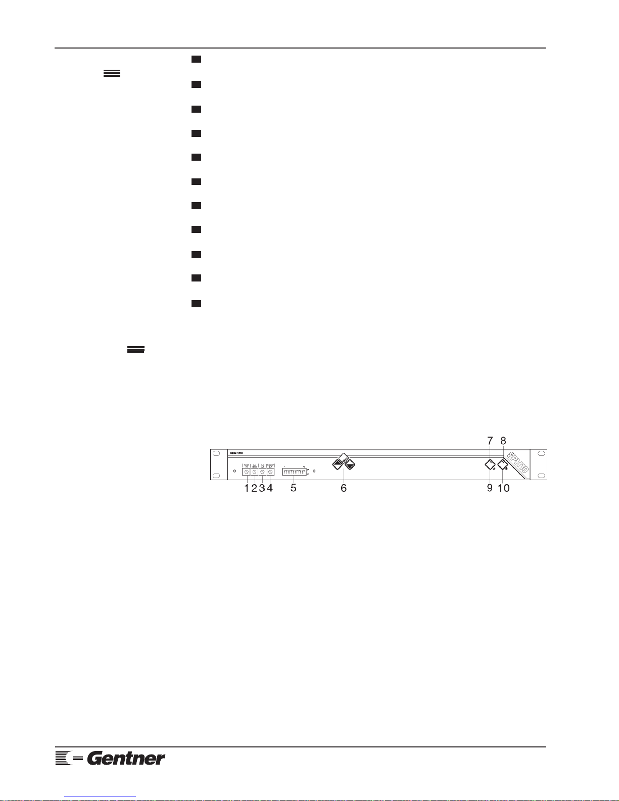
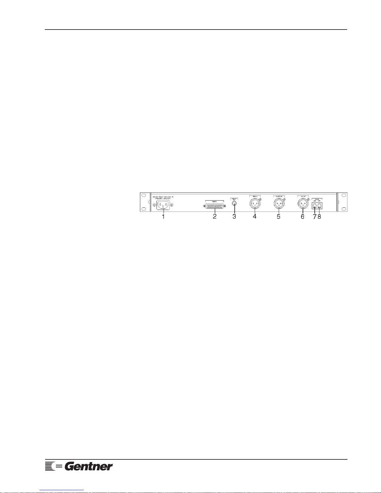
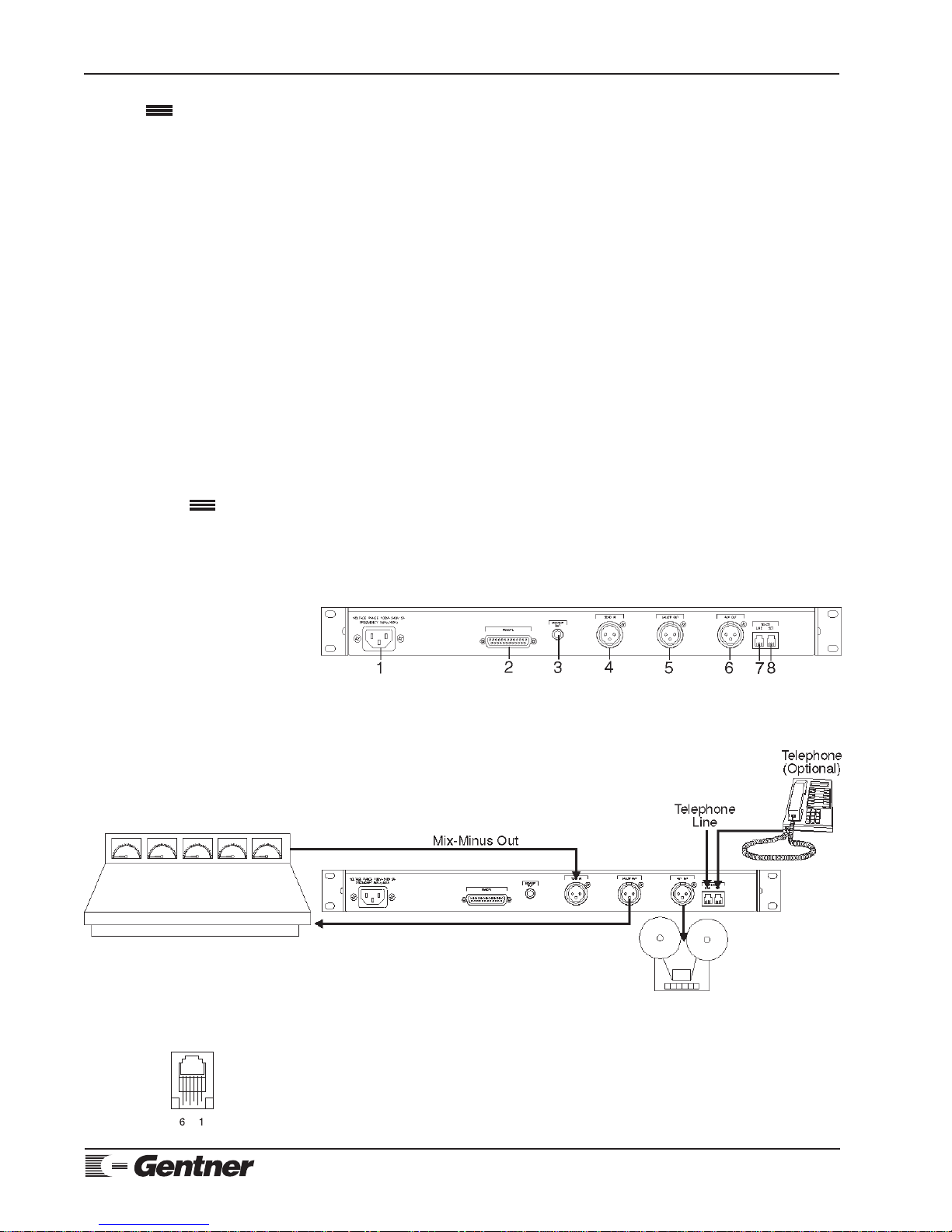
Step 2 — Back-Panel Connections
Remote Control
If using a remote control for parallel control and hybrid status, plug it into
the DB25 REMOTE connector [2] (Figure 7, left). For pinouts, see
Appendix A: Connector Pinouts (Page 13).
Send In
Connect the SEND IN female XLR plug [5] (See Figure 8, left.) to the studio
console. This is balanced line-level audio.
Caller Out
Connect the SPH10’s CALLER OUT audio output to an input on your audio
console [5] (Figure 9, left). This male XLR socket’s audio must contain a
mix-minus.
Aux Out
Connect his male XLR connector [6] (See Figure 10, left, bottom.) to your
recording device. This connector contains caller audio only. Select the AUX
Mix dip switch to create a mix of send and caller on this connector.
Monitor Out
Connect a speaker output feed to this quarter-inch TRS jack [3] (See Figure
11, left.) to monitor a 1W-amplified caller signal.
Step 3 — Power Connection
The power cord [1] (See Figure 12, left.) will operate at any level between
100–240Vac, 50–60Hz.
Mix-minus refers to the audio that must be sent to callers to prevent feedback on
the audio system through the hybrid. Mix-minus is a mix of all audio on the
console, minus the caller’s audio. Without a mix-minus feed, the caller audio
appearing on the console will be sent back to the caller, where it will be
retransmitted to the studio via the caller’s telephone. This feedback can create
anything from echo to a howling squeal. Many broadcast consoles provide a mix-
minus feed via a telephone module.
When using the SPH10 with mix-minus, there are several ways of going about
generating external mix-minus. If a mixing console is used to feed the SPH10’s
SEND input, the audio going down the line must not contain any caller audio.
There are five ways to accomplish this: separate mix channel, internal mix bus,
“build your own” mix-minus, discrete microphone mixer and one-channel send.
Separate Mix Channel
If the console has an extra mixing output channel, use this channel to mix all
the audio you want to send to the SPH10 except the channel that will be
connected to caller audio.
Internal Mix Bus
Mix-minus refers to a sum of all the audio sources in the console minus the
caller audio. Many console manufacturers provide this feature as a telephone
module.
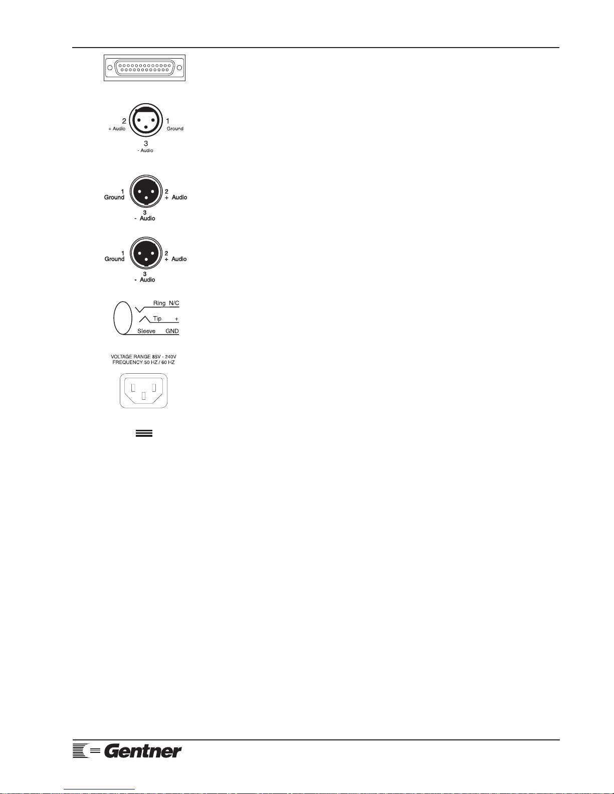
Figure 7.Remote DB25 connector
Figure 12. SPH10power module
Mix-Minus
Figure 11. SPH10monitor RCA jack
Figure 8. SendIn femaleXLRconnector
Figure 9. CallerOut male XLR connector
Figure 10. AuxOut male XLR connector