Geokon 8020-59 User manual

No part of this instruction manual may be reproduced, by any means, without the written consent of Geokon, Inc.
The information contained herein is believed to be accurate and reliable. However, Geokon, Inc. assumes no responsibility for
errors, omissions, or misinterpretation. The information herein is subject to change without notification.
Copyright © 2006 – 2018 by Geokon, Inc.
(Doc Rev J, 05/18/2018
Instruction Manual
Model 8020-59
Vibrating Wire to Analog Converter


Warranty Statement
Geokon, Inc. warrants its products to be free of defects in materials and workmanship, under
normal use and service for a period of 13 months from date of purchase. If the unit should
malfunction, it must be returned to the factory for evaluation, freight prepaid. Upon examination
by Geokon, if the unit is found to be defective, it will be repaired or replaced at no charge.
However, the WARRANTY is VOID if the unit shows evidence of having been tampered with
or shows evidence of being damaged as a result of excessive corrosion or current, heat, moisture
or vibration, improper specification, misapplication, misuse or other operating conditions outside
of Geokon's control. Components which wear or which are damaged by misuse are not
warranted. This includes fuses and batteries.
Geokon manufactures scientific instruments whose misuse is potentially dangerous. The
instruments are intended to be installed and used only by qualified personnel. There are no
warranties except as stated herein. There are no other warranties, expressed or implied, including
but not limited to the implied warranties of merchantability and of fitness for a particular
purpose. Geokon, Inc. is not responsible for any damages or losses caused to other equipment,
whether direct, indirect, incidental, special or consequential which the purchaser may experience
as a result of the installation or use of the product. The buyer's sole remedy for any breach of this
agreement by Geokon, Inc. or any breach of any warranty by Geokon, Inc. shall not exceed the
purchase price paid by the purchaser to Geokon, Inc. for the unit or units, or equipment directly
affected by such breach. Under no circumstances will Geokon reimburse the claimant for loss
incurred in removing and/or reinstalling equipment.
Every precaution for accuracy has been taken in the preparation of manuals and/or software,
however, Geokon, Inc. neither assumes responsibility for any omissions or errors that may
appear nor assumes liability for any damages or losses that result from the use of the products in
accordance with the information contained in the manual or software.

TABLE of CONTENTS
1. INTRODUCTION .................................................................................................................................................. 1
2. INSTALLING AND CONFIGURING THE 8020-59 SOFTWARE APPLICATION ..................................... 2
2.1 CONFIGURING THE COM PORT ........................................................................................................................... 5
3. QUICK START (SINGLE CHANNEL)............................................................................................................... 7
4. SINGLE AND MULTI-CHANNEL OPERATION............................................................................................10
4.1 THEORY OF OPERATION.....................................................................................................................................10
4.2 OPERATING MODES ...........................................................................................................................................11
4.2.1 Single Channel Mode................................................................................................................................11
4.2.2 16-Channel Multiplexed Mode..................................................................................................................12
4.2.3 32-Channel Multiplexed Mode..................................................................................................................13
4.3 CONVERSION TO “DIGITS” .................................................................................................................................14
4.4CONNECTION TO A VOLTAGE INPUT DAS..........................................................................................................15
4.5 CONNECTION TO A CURRENT INPUT DAS..........................................................................................................15
4.6 TEMPERATURE MEASUREMENT .........................................................................................................................16
5. COMMUNICATIONS ..........................................................................................................................................17
5.1 COMMAND LINE INTERFACE..............................................................................................................................17
6. 8020-59 WINDOWS APPLICATION..................................................................................................................20
6.1 SOFTWARE INSTALLATION.................................................................................................................................20
6.2 STARTING THE 8020-59 APPLICATION ...............................................................................................................20
6.3 COMMUNICATIONS TIMEOUT ERROR .................................................................................................................20
6.4 SINGLE CHANNEL CONFIGURATION...................................................................................................................21
6.5 16-CHANNEL CONFIGURATION ..........................................................................................................................22
6.6 32-CHANNEL CONFIGURATION ..........................................................................................................................25
APPENDIX A. SPECIFICATIONS.........................................................................................................................26
A.18020-59 SPECIFICATIONS ..................................................................................................................................26
A.2 MULTIPLEXER TIMING SPECIFICATIONS............................................................................................................27
APPENDIX B. THERMISTOR TEMPERATURE DERIVATION.....................................................................28
APPENDIX C. WIRING CONFIGURATIONS.....................................................................................................29
C.1 VOLTAGE OUTPUT –SINGLE CHANNEL MODE (DIGITAL I/O DAS) ..................................................................29
C.2 VOLTAGE OUTPUT –16-CHANNEL MODE (DIGITAL I/O DAS) .........................................................................30
C.3 VOLTAGE OUTPUT –32-CHANNEL MODE (DIGITAL I/O DAS) .........................................................................31
C.4 CURRENT OUTPUT –SINGLE CHANNEL MODE (DIGITAL I/O DAS) ..................................................................32
C.5 CURRENT OUTPUT –16-CHANNEL MODE (DIGITAL I/O DAS): ........................................................................33
C.6 CURRENT OUTPUT –32-CHANNEL MODE (DIGITAL DAS)................................................................................34
C.7 VOLTAGE OUTPUT –SINGLE CHANNEL MODE (PLC DAS) ..............................................................................35
C.8 VOLTAGE OUTPUT –16-CHANNEL MODE (PLC DAS)......................................................................................36
C.9 VOLTAGE OUTPUT –32-CHANNEL MODE (PLC DAS)......................................................................................37
C.10 CURRENT OUTPUT –SINGLE CHANNEL MODE (PLC DAS).............................................................................38
C.11 CURRENT OUTPUT –16-CHANNEL MODE (PLC DAS)....................................................................................39
C.12 CURRENT OUTPUT –32-CHANNEL MODE (PLC DAS)....................................................................................40
APPENDIX D. DATA REDUCTION ......................................................................................................................41
D.1 PRESSURE CALCULATION..................................................................................................................................41
D.2 TEMPERATURE CORRECTION.............................................................................................................................42
D.3 BAROMETRIC CORRECTION (REQUIRED ONLY ON NON-VENTED TRANSDUCERS)...............................................43
APPENDIX E. SAMPLE CALIBRATION REPORT ...........................................................................................44
APPENDIX F. IMPROVING THE ACCURACY OF CALCULATED PRESSURES.......................................45
APPENDIX G. BAROMETRIC CORRECTION (NON-VENTED TRANSDUCERS ONLY).........................46

FIGURES
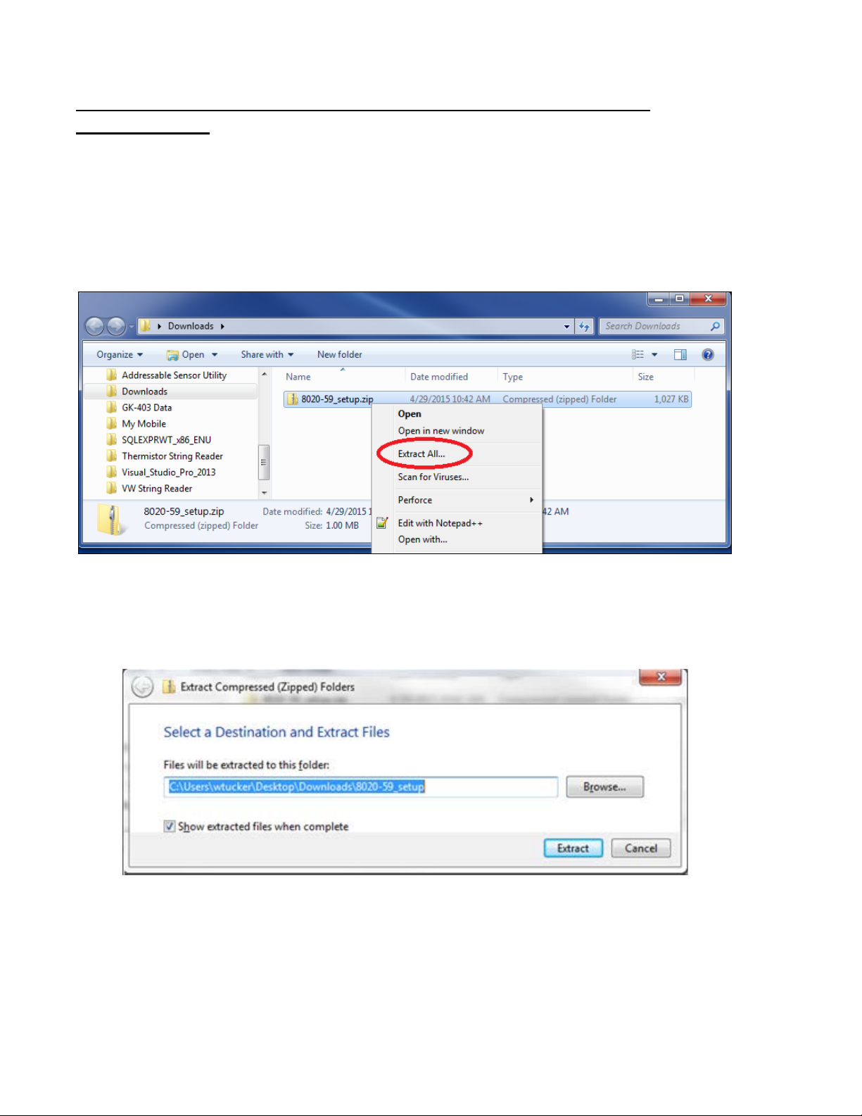
FIGURE 1-EXTRACTING THE 8020-59 INSTALLER .........................................................................................................2
FIGURE 2-SELECT DESTINATION FOLDER .....................................................................................................................2
FIGURE 3-EXTRACTED 8020-59 INSTALLER .................................................................................................................3
FIGURE 4-INSTALL WIZARD,START SCREEN................................................................................................................3
FIGURE 5-INSTALL WIZARD,CHOOSE USERS ...............................................................................................................3
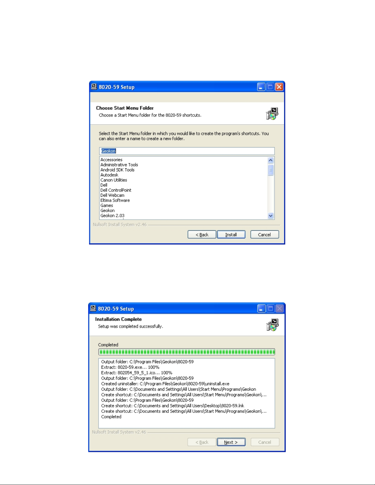
FIGURE 6-INSTALL WIZARD,CHOOSE START MENU FOLDER.......................................................................................4
FIGURE 7-INSTALL WIZARD,INSTALLATION COMPLETE ..............................................................................................4
FIGURE 8-INSTALL WIZARD,LAUNCH 8020-59 APPLICATION......................................................................................5
FIGURE 9-8020-59 SOFTWARE APPLICATION,STARTUP DIALOG..................................................................................5
FIGURE 10 -COMMUNICATIONS PARAMETERS DIALOG .................................................................................................6
FIGURE 11 -SINGLE CHANNEL CONFIGURATION SCREEN ..............................................................................................8
FIGURE 12 -SINGLE CHANNEL MONITOR.......................................................................................................................8
FIGURE 13 -CONTROL SIGNAL SEQUENCE:SINGLE CHANNEL MODE ..........................................................................11
FIGURE 14 -CONTROL SIGNAL SEQUENCE:16-CHANNEL MODE (CHANNELS ONE AND TWO ONLY) ..........................12
FIGURE 15 -CONTROL SIGNAL SEQUENCE:32-CHANNEL MODE (CHANNELS ONE THROUGH FOUR ONLY) ................13
FIGURE 16 -COMMUNICATION TIMEOUT WARNING MESSAGE ....................................................................................20
FIGURE 17 -16-CHANNEL CONFIGURATION SCREEN ...................................................................................................22
FIGURE 18 -16-CHANNEL MONITOR SCREEN...............................................................................................................23
FIGURE 19 -CHANNEL ONE MONITOR .........................................................................................................................24
FIGURE 20 -32-CHANNEL MONITOR SCREEN...............................................................................................................25
FIGURE 21 -CHANNEL THREE MONITOR......................................................................................................................25
FIGURE 22 -16-CHANNEL MULTIPLEXER TIMING REQUIREMENTS ..............................................................................27
FIGURE 23 -32-CHANNEL MULTIPLEXER TIMING REQUIREMENTS ..............................................................................27
FIGURE 24 -CONNECTION EXAMPLE FOR ONE CHANNEL 8020-59 WITH VOLTAGE OUTPUT TO DIGITAL I/O DAS.....29
FIGURE 25 -CONNECTION EXAMPLE FOR 16-CHANNEL MULTIPLEXER,8020-59 WITH VOLTAGE OUTPUT AND DIGITAL
I/O DAS .............................................................................................................................................................30
FIGURE 26 -CONNECTION EXAMPLE FOR 32-CHANNEL MULTIPLEXER,8020-59 WITH VOLTAGE OUTPUT AND DIGITAL
I/O DAS .............................................................................................................................................................31
FIGURE 27 -CONNECTION EXAMPLE FOR ONE CHANNEL 8020-59 WITH CURRENT OUTPUT TO DIGITAL I/O DAS .....32
FIGURE 28 -CONNECTION EXAMPLE FOR 16-CHANNEL MULTIPLEXER,8020-59 WITH CURRENT OUTPUT AND DIGITAL
I/O DAS .............................................................................................................................................................33
FIGURE 29 -CONNECTION EXAMPLE FOR 32-CHANNEL MULTIPLEXER,8020-59 WITH CURRENT OUTPUT AND DIGITAL
I/O DAS .............................................................................................................................................................34
FIGURE 30 -CONNECTION EXAMPLE FOR ONE CHANNEL.8020-59 WITH VOLTAGE OUTPUT,8020-59 PLC AND PLC
DAS ...................................................................................................................................................................35
FIGURE 31 -CONNECTION EXAMPLE FOR 16-CHANNEL MULTIPLEXER,8020-59 W/VOLTAGE OUTPUT,8020-59 PLC
AND PLC DAS....................................................................................................................................................36
FIGURE 32 -CONNECTION EXAMPLE FOR 32-CHANNEL MULTIPLEXER,8020-59 W/VOLTAGE OUTPUT,8020-59 PLC
AND PLC DAS....................................................................................................................................................37
FIGURE 33 -CONNECTION EXAMPLE FOR ONE CHANNEL 8020-59 WITH CURRENT OUTPUT,8020-59 PLC AND PLC
DAS ...................................................................................................................................................................38
FIGURE 34 -CONNECTION EXAMPLE FOR 16-CHANNEL MULTIPLEXER,8020-59 W/CURRENT OUTPUT,8020-59 PLC
AND PLC DAS....................................................................................................................................................39
FIGURE 35 -CONNECTION EXAMPLE FOR 32-CHANNEL MULTIPLEXER,8020-59 W/CURRENT OUTPUT,8020-59 PLC
AND PLC DAS....................................................................................................................................................40
FIGURE 36 -VIBRATING WIRE PRESSURE TRANSDUCER CALIBRATION REPORT..........................................................44
Table of contents
Other Geokon Media Converter manuals
Popular Media Converter manuals by other brands

H&B
H&B TX-100 Installation and instruction manual

Bolin Technology
Bolin Technology D Series user manual

IFM Electronic
IFM Electronic Efector 400 RN30 Series Device manual

GRASS VALLEY
GRASS VALLEY KUDOSPRO ULC2000 user manual

Linear Technology
Linear Technology DC1523A Demo Manual

Lika
Lika ROTAPULS I28 Series quick start guide

Weidmuller
Weidmuller IE-MC-VL Series Hardware installation guide

Optical Systems Design
Optical Systems Design OSD2139 Series Operator's manual

Tema Telecomunicazioni
Tema Telecomunicazioni AD615/S product manual

KTI Networks
KTI Networks KGC-352 Series installation guide

Gira
Gira 0588 Series operating instructions

Lika
Lika SFA-5000-FD user guide