Geonav 11 Sun Manual

User and Installation Guide
SUNSHINE
FLASH
SUN
11
8SUNSHINE

READTHISWARNINGBEFOREUSINGTHEGEONAV
WARNING
THEELECTRONICCHARTISANAIDTONAVIGATIONDE-
SIGNEDTOFACILITATETHEUSEOFAUTHORIZEDGOV-
ERNMENTCHARTS,NOTTOREPLACETHEM.
ONLYOFFICIALGOVERNMENTCHARTSANDNOTICES
TO MARINERS CONTAIN ALL INFORMATION NEEDED
FOR THE SAFETY OF NAVIGATION AND, AS ALWAYS,
THE CAPTAIN IS RESPONSIBLE FOR THEIR PROPER
USE.
The use of the GEONAV implies knowledge and accep-
tanceof thiswarning bythe user.
NOTE: This guide applies to the GEONAV 11 Flash, GEONAV 11 Sun, GEONAV 11
Sunshine and GEONAV 8 Sunshine models. The functions peculiar to each model are
highlighted in the text. Unless otherwise specified, functions are intended as common
to all models. Unless otherwise specified, although figures refer to the 11”model, they
also apply to the 8”model. Technical characteristics and functions described in this
manual are subject to change as a result of improvements or changes to the product.

4 5
CHARACTERISTICS
General characteristics
• Configurable internal software versions (standard/ad-
vanced)
• Easy Pilot function for easy and direct control of autopilot
• Possibility to transfer routes, tracks and markers from one
plotter station to another through network connection
• EBL and VRM functions
• Multiple display of tracks
• Storage of track data including significant additional in-
formation such as date, time, latitude/longitude, depth,
temperature, wind data, etc.
• GOTO function (Waypoint, Port, Nearest Service, Marker,
Track, Lat/Lon, R/B)
• Screen Amplifier™ function
• Autozoom™ function
• Overzoom™ function
• 8 marker shapes, 8-character name
• Reverse route function
• Selectable depth units (meters, feet and fathoms)
• Cartography with port services and Tides and Currents
data
• 16 zoom levels
• Heading vector
• Speed and heading filters
• CompactFlash™ cartridge
• Storage of routes, tracks and markers in separate files on
CompactFlash™ cartridges
• NMEA 0183 interface (ver. 2.03)
• NMEA 2000-ready interface
• Display of depth and water temperature data (if interfaced
with an echosounder)
• Display of wind data and automatic activation of the sail-
ing software version (if interfaced with wind instruments)
• Backlit keypad
INTRODUCTION
The GEONAV is a chart plotter that can be interfaced with a
GPS receiver, autopilot and other onboard instruments, and
allows displaying the boat’s geographical position with respect
to an electronic chart.
Thanks to the GEONAV and a NAVIONICS electronic chart,
you will never get lost even in case of fog, rain or dark.
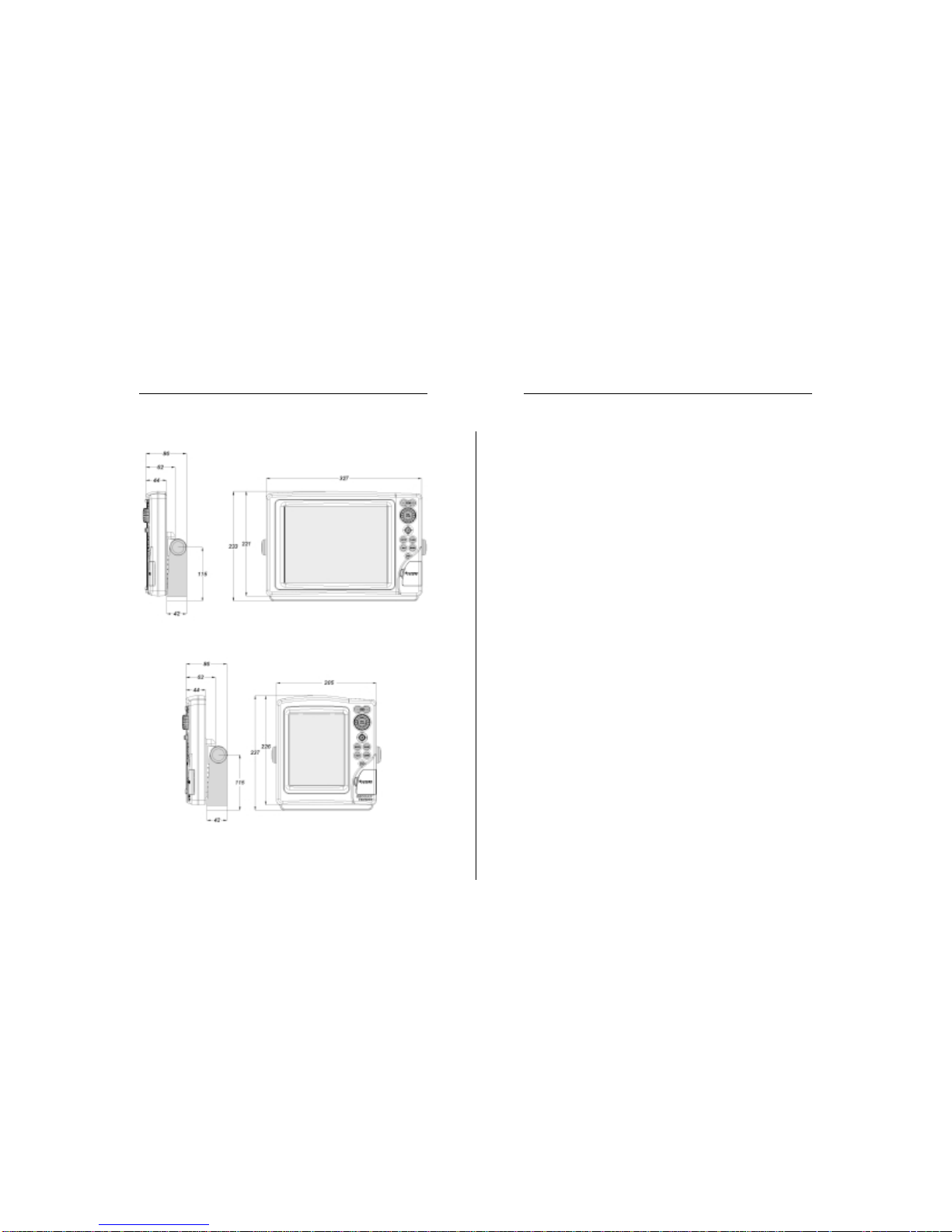
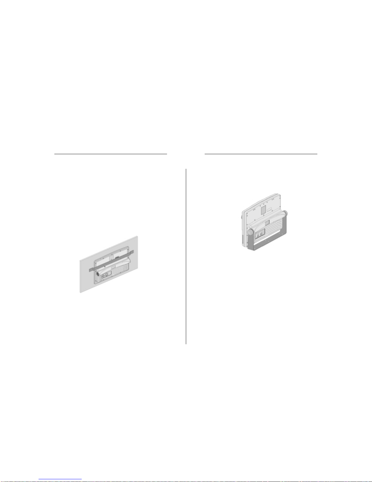
The GEONAV, available with either sunlight-readable color
display or sunlight-readable monochrome display, has been
designed to allow flush mounting. Equipped with an easy-to-
use keyboard, the GEONAV allows controlling the autopilot
directly from the plotter (Easy Pilot function) and, thanks to
the unlimited capacity of the new CompactFlash™ cartridges
- that can also be used on PCs as personal hard disks - can
store a large amount of route, track and marker data.
The GEONAV is equipped with three software versions (stan-
dard, advanced and sailing), automatically selected according
to the instrument connected. The connecting supports both
the NMEA 0183 standard protocol and the new NMEA 2000
network, suitable for the network connection of multiple sta-
tions or several instruments of different brands.
The Route functions will allow you to plan a trip, while, thanks
to NAVIONICS electronic charts, you will always know ex-
actly the boat’s position. NAVIONICS charts are available for
all the most popular boating areas and can be used in addition
to official paper charts to obtain additional information, such
as the availability of port services as well as tides and cur-
rents data. NAVIONICS electronic charts are available world-
wide from authorized NAVIONICS dealers.
Should new functions be available in the future, it will be
possible to update the GEONAV internal software at any
NAVIONICS dealer.
Introduction Characteristics

6 7
• Number of routes, tracks and markers: unlimited, depend-
ing on the size of the CompactFlash™ used
Interface characteristics
• Standard NMEA 0183 sentences
- from position sensor:
GLL, VTG, GGA, RMC, GSV, ZDA, RMA, GSA
- from depth sounder:
DBT, MTW
- to autopilot:
APA, APB, XTE, RMB, BWC, GLL, VTG
• CAN protocol, compatible with NMEA 2000
If received from the GPS, the following sentences are trans-
mitted:
GGA, RMC, ZDA.
Accessories
• Bracket for detachable installation
• Gasket and drilling template for panel mounting
• Plastic frame and drilling template for flush mounting (op-
tional on the Sunshine 8 model)
• Power supply cable
• Auxiliary power supply cable
• User and Installation Guide
• Protection cap
• Carrying case
NOTE: The plotter can be interfaced with instruments featuring the new NMEA 2000
protocol. However, as of the plotter is put on sale, the final issue of the NMEA 2000
standard is not available yet. For this reason, to obtain full efficiency from network
connection, the plotter software may need updating. For further information, consult
your local GEONAV dealer.
• Color LCD, TFT 10.4”
• Monochrome LCD, STN 9.4”
• Color LCD, transflective TFT 10.4”, high brightness, sun-
light visible
• Color LCD, TFT 6.4”, sunlight visible
Electrical characteristics
• Power supply: 10 to 36 Vd.c.
• Power consumption: Max. 13 W
• Power consumption: Max. 16 W
• Power consumption: Max. 20 W
• NMEA 2000 network load: 2
• Auxiliary voltage output: 10 to 36 Vd.c.
(same as input voltage) - Max. 250 mA
• Protection against: Reverse polarity
Input overvoltage (up to 40 Vd.c.)
Overcurrent at auxiliary voltage out-
put (over 250 mA)
• Operating temperature: 0°C to +50°C
• Operating temperature: 0°C to +55°C
• Storage temperature: -20°C to +60°C
• Storage temperature: -20°C to +70°C
Memory characteristics
• Up to 100 waypoints per route
• Up to 5000 trackpoints (multiple tracks)
• Up to 3000 markers per group
Flash
Sun
Sunshine 11
Sunshine 8
Flash
Sun
Sunshine 8
Sunshine 11
Flash
Sun
Sunshine
Sunshine
Flash
Sun
Characteristics

8 9
INSTALLATION AND PRECAUTIONS
Precautions
To avoid electromagnetic interference, the GEONAV must be
positioned at least 0.72 m (Flash, Sun), 0.50 m (Sunshine 11)
or 0.45 m (Sunshine 8) away from the magnetic compass.
Wherever possible, the power supply cable shield should be
connected to the boat’s ground plate.
The GEONAV is water resistant but not waterproof, and should
not be immersed totally in water.
The cartridge slot cover, located on the plotter’s right-hand
side, should always be kept closed and opened only when
replacing cartridges. Make sure that the cartridge replacement
is carried out as the unit is perfectly dry and that no water
enters the unit.
Rear connectors, when not in use, should always be protected
by the appropriate rubber covers.
Cleaning
It is recommended the use of a non-alcoholic product to clean
the glass, since alcoholic products may damage the glass sur-
face or make it opaque.
Panel mounting
Locate the area where the GEONAV is to be installed, then
use the drilling template supplied with the plotter to properly
cut holes and sockets out of the instrument’s panel.
The neoprene adhesive gasket supplied must be applied to
the GEONAV rear side to avoid moisture penetration and to
reduce vibrations.
Mounting screws must be 4 mm in diameter and maximum 5
mm in length, plus the thickness of the panel. Do not exceed
tightening the screws, in order to avoid damaging the screw
seats.
Installation and Precautions
Characteristics

10 11
Flush mounting
Locate the area where the GEONAV is to be installed, then
use the cutting template supplied with the plotter to cut the
panel.
Apply a layer of silicone glue (the use of black colored glue is
recommended, in order to prevent the area from going yellow
when exposed to sunlight) to the plastic frame rear part; place
the frame into the socket cut out of the panel, so that the
frame edge leans against the panel.
Make sure that the frame and the panel are correctly fixed; if
necessary, apply additional metal brackets (not supplied in
the package) as shown in the figure below.
Let the silicone glue dry, then apply the neoprene gasket to
the plotter rear side, insert the instrument into the frame and
lock it by the screws supplied.
Do not exceed tightening the screws, in order to avoid damag-
ing the screw seats.
Bracket mounting
Fix the bracket to the boat’s dashboard by screws 6mm in
diameter.
Installation and Precautions

12 13
2. NMEA 2000 network connection
white wire NET H pin 3
blue wire NET L pin 4
black wire NET C pin 6
red wire NET S pin 7
SHIELD pin 5
WARNING: To ensure a safe installation, the shields of connecting cables should be
grounded, i.e., connected to the boat’s ground.
NOTE: Network connection requires the use of suitable connectors and an auxiliary
power supply, as established by the NMEA 2000 standard. Technical features and
connection modes are reported in the technical document issued by the National
Marine Electronic Association (for further information, go to the http://www.nmea.org
web site). Only skilled personnel should be charged with making the connection.
CONNECTIONS
Power supply and data connector (9 pins)
1. Power supply
red wire + VDC pin 1
black wire GND pin 2
2. NMEA 0183 data input
brown wire GPS IN + pin 3
yellow wire GPS IN - pin 4
3. NMEA 0183 data output
violet wire DATA OUT + pin 5
white wire DATA OUT - pin 6
4. Auxiliary output voltage (Vaux)
blue wire Vaux+, 250mA * pin 7
green wire GND pin 8
SHIELD pin 9
* Vaux voltage is the same as the plotter’s input voltage.
If sent by the position sensor, the following NMEA messages
are transmitted to external devices (e.g., autopilot):
APB - XTE - RMB - BWC - GLL - VTG
The GEONAV will add the following messages (if received
from the position sensor):
GGA - RMC - ZDA
Auxiliary connector (7 pins)
Allows connecting the GEONAV to an auxiliary instrument
equipped with an NMEA 0183 interface (e.g., echosounder
and mast head transducer), as well as to the NMEA 2000 net-
work.
1. NMEA 0183 auxiliary data input
brown wire DATA IN + pin 1
yellow wire DATA IN - pin 2
Connections

14 15
Removing the CompactFlash™
Make sure that the plotter is perfectly dry.
Open the cartridge slot cover located on the plotter’s front
side, then extract the cartridge.
WARNING: Always use CompactFlash™cartridges certified by Navionics. The
use of non-certified cartridges may result in improper operation of the unit.
The CompactFlash™ cartridges can be used as a mass-storage
with any PC computer, so can be the cartridge used by the
plotter. However, the plotter needs to find some free space in
the cartridge in order to work properly. Prior to use a new
cartridge, always make sure that there are at least 2.5MB of
free space.
WARNING: Be careful when handling the cartridge files by using the PC. Windows
allows deleting and moving files easily, therefore pay attention when using Windows
Explorer not to erase the content of the \NAVIONIC and \GEONAV folders. Damaging
the files stored in such directories may result in loss of data or improper operation of
the unit.
CARTRIDGE INSTALLATION
Installing the CompactFlash™
Open the cartridge slot cover located on the plotter’s front
side.
Insert the cartridge into the appropriate slot, with the label
side (side with a small arrow) towards the right, and push it
down.
Close the cover exercising light pressure and check that it is
perfectly closed, in order to avoid any water infiltration.
NOTE: Make sure of inserting the cartridge correctly. Should you try to insert the
wrong side of the cartridge, full insertion into the slot is hampered. Any further attempt
to force the cartridge into the slot may damage the cartridge or the plotter. This kind of
damage is not covered by the warranty.
Cartridge Installation

16 17
• A port
• The nearest port service
Positions the cursor on the coordinates selected (Lat/ Lon or
Trk).
CLR
• Cancels the setting of data in the windows
• Cancels the option selection from the menu
Cursor mode:
• Deletes all waypoints, starting from the last entered
• Deletes the waypoint pointed by the cursor
• Deletes the marker pointed by the cursor
Navigation mode:
• Deletes the whole current route
KNOB
• Adjusts EBL/VRM parameters
• Selects the several options from the menu windows
• Scrolls letters and numbers when entering data in the
windows
If pressed:
Navigation mode:
• Switches from EBL to VRM
Menu:
• Switches from vertical to horizontal scrolling and confirms
the selection
NOTE: Both the joystick and the knob (press the knob to switch from horizontal to
vertical movement) can be used to select items from the menu, as well as to set data
(e.g., marker’s name, local time, etc.). In the remainder of the document, reference is
made to the joystick only.
PAGE
• Cancels a selection
KEYBOARD
ZOOM-/ZOOM+
• Increases/decreases
the chart range
• Enables/disables the
Autozoom function
JOYSTICK (right/left - up/down)
• Moves the cursor
across the screen
• Switches from Naviga-
tion mode to Cursor
mode
• Selects the options
from menus and
submenus
If pressed (ENTER):
Cursor mode:
• Inserts a waypoint at
the cursor’s position
Navigation mode:
• Changes the target
waypoint (Motor boat-
ing)
• Sets the wind speed
(Sailing)
Menu:
• Confirms a selection
GOTO
Plots a route to:
• A new target waypoint
• A marker
Keyboard

18 19
DIAGNOSTIC
The GEONAV features a diagnostic program to verify its cor-
rect performance, once installed, and to detect problems that
may occur during the use of the unit.
To access the diagnostic program, keep pressed any key but
CLR, while pressing the PWR key.
The GEONAV will switch on and carry out automatically a
test of the whole system; as soon as the memory test is com-
pleted, the program will test the LCD, the CompactFlash™
card and the keyboard. Press ENTER to run one test, CLR to skip
to the next one. To exit from the keyboard test, press CLR
twice.
Once the keyboard test is completed, the diagnostic program
allows checking the messages received from the GPS trough
the NMEA 0183 port. Hold the knob pressed to freeze the
messages on the screen, then release it to keep on displaying
the new messages sent by the GPS. To test channel 1 (depth
sounder or wind instrument), press GOTO. Press CLR to quit.
After the keyboard, the diagnostic program will test the inter-
nal non-volatile memory and the backlight. Press ENTER to run
one test, CLR to skip to the next one.
Once terminated all tests, press ENTER to re-boot the unit.
WARNING: The internal memory can be cleared by pressing simultaneously the
PWR and CLR keys. This operation will delete all the settings stored in the GEONAV
and restore factory settings.
NOTE: In case of damaged cartridge or abnormal power spikes, the unit might lock,
requiring a power shutdown to restart. In that case, the unit can be turned off without
the need of detaching the power, by simply pressing the GOTO, PAGE and CLEAR
keys at the same time. This function is useful if the unit is panel mounted or flush
mounted and the power switch cannot be easily accessed.
Cursor mode:
• Switches from Cursor mode to Navigation mode
Navigation mode:
• Turns the pages of navigation data
MARK
• Inserts a marker at the boat’s position (in Navigation mode),
or at the cursor’s position (in Cursor mode)
PWR
• Switches the GEONAV on
• Opens the contrast/brightness window
• Switches the GEONAV off (if held pressed for more than 3
seconds)
Keyboard Diagnostic

20 21
NAVIONICS ELECTRONIC CHARTS
The GEONAV includes a built-in world map. Additional car-
tography details relative to a specific area of navigation are
available from the CompactFlash™ cartridges storing
NAVIONICS Seamless™ electronic charts.
NAVIONICS electronic charts contain the following data:
To display chart boundaries, press the PAGE key to display the
menu, select SETUP, then the CHART BOUNDARY option
and, by the joystick, select ON/OFF to enable/disable the
boundaries of the charts stored in the cartridge.
A small square will locate the area covered by the cartridge
installed; position the cursor within the square and then de-
crease the chart range by the ZOOM+ key to display the details
of the area covered by the cartridge.
The maximum detail level is obtained within port plans and
can reach 1/8 nautical mile (the smallest point on screen is
equivalent to approximately 1 meter), depending on the car-
tridge type and coverage.
Increasing/decreasing the chart range
Press the -ZOOM+ key.
Displaying depth contours, geographical names and ports
Press the PAGE key to display the menu, select SETUP and
enable the options desired (DEPTH CONT. or NAMES) by the
joystick.
Converting depth values into the units set
Press PAGE to display the menu,
select SETUP, DEPTH UNITS and
then set the unit desired in
meters, feet or fathoms. The
GEONAV will convert all the
depth values in the unit selected,
making them appear like those re-
ported in the official nautical
charts (see the figure).
Displaying navaid characteristics
Position the cursor on the navaid symbol
A window will show the characteristics of the navaid selected.
NAVIONICS Electronic Charts

22 23
Description of navaid characteristics:
Displaying port services
NOTE: This function is available only with the NAVIONICS cartridges containing the
Port Services feature.
Position the cursor on the port icon and press ENTER.
A window will show the list of the port services available in
the port selected. Choose the service desired by the joystick.
The number and the type of icon differ from one port to an-
other.
Port services are identified by the following icons:
The number and the type of service available will depend on
the cartridge installed.
Displaying Tides and Currents data
NOTE: This function is available only with the NAVIONICS cartridges containing
Tides and Currents data.
Position the cursor on the icon of a Tide or
Current station, then press ENTER.
A graph will show the tide rate or the tidal stream relevant to
the station selected, as measured during the current day.
ABBREVIATIONS FOR LIGHT ABBREVIATIONS FOR COLOUR
AL alternating AM amber
F fixed B black
FLL fixed and flashing BL blue
FL (...) group flashing G green
FL single flashing OR orange
IQ interrupted quick R red
OC single-occulting VL violet
OC (...) composite group occulting W white
Q continuous group Y yellow
ABBREVIATION FOR PERIOD ABBREVIATION FOR RANGE
..S xx seconds ..M xx nautical miles
Healthandfirstaid
services
Touristservicesand
shops
Engine,boat,
electronicand
otherrepairs
Information
andport
authorities
Tidestation
Currentstation
Customerservices
Water
Fuel
NAVIONICS Electronic Charts

24 25
GRAPHIC ITEMS
Besides chart data, the GEONAV displays some graphic items
useful during navigation.
The figure below shows some of these items.
1 - Marker
Indicates a point of interest associated with a symbol, a name
and a color.
2 - Track segment
Recording of the track actually followed by the boat; the track
is displayed as a colored dashed line.
3 - Boat’s position
Boat’s position according to the data received from the GPS
receiver.
4 - Rubber band
Line joining the last waypoint entered to the manual cursor,
or the boat’s position to the manual cursor when no waypoint
has been entered.
To delete this band, press the PAGE key and switch to Naviga-
NAVIONICS Electronic Charts Graphic Items

26 27
FUNCTIONAL CHARACTERISTICS
This chapter describes some of the most important functions
of the GEONAV, as well as the terms most commonly used in
this document.
Switching on/Switching off the unit
To switch the GEONAV on, press the PWR key. To switch it
off, keep the PWR key pressed for more than 3 seconds.
Welcome page
At start-up, the GEONAV displays a welcome page whose text
(e.g., the boat’s name) can be edited by the Setup menu (see the
Setup Section). To freeze the page displayed, press PAGE. To
unfreeze the page and continue with the instrument’s opera-
tion, press PAGE again.
Standard/Advanced modes
The GEONAV can operate in Standard mode or in Advanced
mode. In Advanced mode, even the less frequently used func-
tions, such as data saving to cartridges and heading/speed
filters, are available. In Standard mode, some menus feature
less options, thus making it easier to use the plotter. To choose
the operating mode desired, press the PAGE key to display the
menu, select SETUP and then SELECT MODE.
Depth sounder
If connected to a depth sounder via NMEA, the GEONAV will
enable the depth sounder mode, showing a graph of the sea
bed or the relevant data in numerical form.
The depth value can be expressed in meters (default value),
feet or fathoms; to select the unit, press PAGE to display the
menu, select SETUP and DEPTH UNITS (M/FT/FA).
Sailing functions
If connected to a mast head transducer (anemometer), the
GEONAV will automatically enable the Sailing mode, once wind
speed and direction data has been received.
Sailing
tion mode.
5 - Route leg
Part of route between two waypoints.
6 - Waypoint
Waypoints are identified by a circle and a number. The route
starting point is marked by the “X”symbol. The target waypoint
is identified by a filled circle, whereas the route leg currently
followed is identified by a thicker line.
7 - Cursor
Indicates the position expressed in geographical coordinates
(latitude and longitude).
It is displayed when the plotter is in Cursor mode.
8 - Heading vector
Indicates graphically the boat’s current route.
9 – North indicator
Indicates the north direction when the Chart rotation func-
tion is enabled.
10 – True wind vector
Indicates the direction of true wind detected by onboard in-
struments.
11 – Layline
Indicates the direction after the next tack or gybe. In order to
achieve the best performance, the tack or gybe should be car-
ried out as soon as the layline crosses the target waypoint.
Sailing
Graphic Items Functional Characteristics

28 29
range before activating the chart rotation. Confirm by press-
ing ENTER.
The northern direction will be indicated by the symbol
Autozoom
With the Autozoom function the GEONAV will always display
automatically the boat’s position and the target waypoint at
the best available chart range. This function is enabled pro-
vided that at least one waypoint has been previously entered.
NOTE: In this document, the functions enabled in Advanced and Sailing modes are
outlined in the text. Unless otherwise specified, functions are intended as common to
all the available modes.
Navigation mode (automatic)
At start-up, the GEONAV automatically enables the Naviga-
tion mode, as soon as the GPS transmits a valid fix; when in
Navigation mode:
•The manual cursor is not displayed
•The depth sounder window can be accessed
This mode is also called automatic because the unit automati-
cally updates the boat’s position on the screen.
Cursor mode (manual)
When in Cursor mode, the manual cursor is displayed. It is
possible to insert, delete and move waypoints, insert and delete
markers, display navaid information, etc., but it is not possible
to gain access to the depth sounder window.
To switch from Navigation mode to Cursor mode, use the
joystick. To go back to Navigation mode, press the PAGE key.
Chart rotation
Charts are traditionally displayed in north-up mode. This,
however, does not correspond to reality. For example, when
traveling southwards, the chart shows, on the right side of
the boat, what is actually located on the left side, and vice
versa.
The Chart Rotation function allows rotating the electronic chart
displayed according to the plotted route (COG - Course Over
Ground), as detected by the GPS receiver. Since the COG value
varies continuously, a filter has been inserted to prevent the
chart from bouncing.
The Chart Rotation function is enabled at a speed greater than
1 knot. To enable the Chart Rotation function, press PAGE to
display the menu, select SETUP, then CHART ROTATION
and ON. A message will prompt the user to select the chart
Without Chart Rotation With Chart Rotation
Functional Characteristics

30 31
To enable these functions, rotate the knob to display the EBL,
position the line on the bearing desired, then press the knob
to enable the VRM ring and adjust its size by rotating the knob
so as to reach the range desired. To edit the values set, press
the knob to switch from the VRM function to the EBL func-
tion. Press MARK to insert a marker where the EBL and VRM
intersect, and ENTER to insert a waypoint.
Range and bearing values are displayed in the top left-hand
corner of the screen, together with the indication of the func-
tion currently enabled.
Press CLR to disable the two functions in sequence.
The VRM ring can also be used to set the range for navigation
from the coast, for example to avoid navigating out of the limit
allowed. In this case, set the EBL to any value, adjust the
VRM ring size as desired, then navigate making sure that at
least one point in the ring is always touching the coast.
Easy Pilot function
The Easy Pilot function allows editing temporarily a route set
and followed by the autopilot, but keeping the route unchanged.
This function is useful to make corrections at
once (e.g., because of other boats or to approach
points of interests), without having to edit the
route planned or disable the autopilot.
To enable this function, rotate the knob and
position the EBL on the new route to follow,
then press ENTER. The EBL will change color,
as the boat starts following the new route; the
planned route will be abandoned, although dis-
played. To go back to the planned route, thus
canceling the temporary correction, press CLR.
NOTE: The Easy Pilot function can be enabled only if a route is present.
To enable the Autozoom function, press ZOOM+ until the
“AUTOZOOM ? ENTER = YES”message is displayed, then
confirm by pressing ENTER. To disable the Autozoom function,
press ZOOM.
When the GEONAV is turned on, and if at least one waypoint
has been previously entered, the Autozoom function will be
automatically enabled.
Screen Amplifier
This function automatically re-
draws the chart according to the
boat’s course, so as to maintain
2/3rds of the screen ahead of the
boat, provided that the boat’s
speed is greater than 3 knots.
To enable/disable the Screen
Amplifier function, press the
PAGE key to display the menu, se-
lect SETUP, the SCREEN AM-
PLIFIER option, then ON or OFF.
This function will be enabled pro-
vided that no waypoint has been
previously entered.
EBL/VRM functions
The EBL (Electronic
Bearing Line) and VRM
(Variable Range
Marker) functions al-
low entering markers
and waypoints as range
and bearing coordi-
nates with respect to
the current position.
Advanced
Functional Characteristics

32 33
Press ENTER to move the GPS boat’s position to the point indi-
cated by the cursor. This operation will save the calibration
for use in future calculations.
NOTE: When the calibration is enabled, the coordinates (latitude/longitude) in the Info
window will be marked by (*).
To cancel calibration, press PAGE to display the menu bar, se-
lect SETUP, CALIBRATION and then OFF.
Local time
This function allows entering local time instead of the Green-
wich time (GMT) supplied by the GPS receiver.
To enter local time, press PAGE to display the menu bar; by the
joystick, select SETUP, TIME REFERENCE and then LOCAL.
The joystick will allow entering local time as well as confirm-
ing the operation. To cancel local time, press PAGE to display
the menu bar, select SETUP, TIME REFERENCE and then
GMT.
Contrast/Brightness
Press the PWR key to display the CONTRAST/LIGHT window.
To switch from one option to the other and to adjust the con-
trast/brightness level, use the joystick. Press the PAGE key to
exit.
Color
Besides displaying color nautical charts, the GEONAV allows
selecting the track and marker colors.
Press the PAGE key to display the menu bar, select TRACK or
MARKER, then COLORS and confirm by pressing ENTER; choose
the color desired and confirm.
The color of markers can also be selected when entered or
edited, whereas the track segment color can be selected by
Overzoom
The Overzoom function allows expanding the chart range.
The Overzoom does not provide any additional chart detail,
only improves the readability of the available information, act-
ing as a magnifying glass.
When the Overzoom is enabled, the unit will warn the user
by:
•Disabling the land filling function
•Adding OVZ after RANGE within the navigation window
To enable/disable the Overzoom function, press PAGE to dis-
play the menu bar, then select SETUP, OVERZOOM and ON/
OFF.
Position calibration
All position sensors are affected by intrinsic errors that make
the boat’s position incorrect (from few meters to several hun-
dred meters).
The position calibration function allows correcting manually
the position error present in all GPS, provided that this error
is not greater than 2 nautical miles.
Press PAGE to display the menu bar, select SETUP, CALIBRA-
TION and then ON. A message will prompt the user to move
the cursor to the boat’s true position, appropriately enlarged
by the ZOOM+ key.
Flash
Sunshine
Functional Characteristics

34 35
QUICK TOUR
We recommend that you use the GEONAV intuitively, since
no damage will be caused by pressing an incorrect button.
Make sure that the GPS re-
ceiver is connected, insert
a Compact Flash™ cartridge
and press the PWR key. At
start-up, the last chart used
will be loaded by default. If
the chart is not found, the
list of NAVIONICS charts
stored into the Compact Flash™cartridge will be displayed.
Select the desired chart by the joystick, then confirm by press-
ing ENTER.
A message will warn the user that electronic nautical charts
do not replace official government charts.
Press the PWR key to turn the display backlight on and adjust
brightness by the joystick; press PAGE to continue.
The Satellite window will show the configuration of the sat-
ellites in use.
As soon as the GPS receiver has obtained a valid fix (it can
take a few minutes), the boat’s position and the relevant area
will be displayed at the best scale available.
The default language is English. To change the language, press
PAGE to display the menu bar, then select SETUP, LANGUAGE
and the desired language by the joystick.
The line, or vector, starting from the boat indicates the boat’s
direction, to be ignored if the boat is stationary.
Two windows will display the boat’s speed, route and chart
scale.
positioning the manual cursor on the segment itself.
The color of chart items can be chosen from DAY, NIGHT or
BRIGHT. Press the PAGE key to display the menu bar, select
SETUP, DISPLAY MODE and then DAY, NIGHT or BRIGHT.
Flash
Sunshine
Functional Characteristics Quick Tour

36 37
progressively. In case of error, waypoints can be deleted by
pressing the CLR key (Cursor mode), starting from the last en-
tered.
To go back to Navigation mode, press PAGE.
If an autopilot is connected to the GEONAV, the plotted route
is automatically followed as soon as the Navigation mode is
enabled.
NOTE: The cursor can be moved to the desired position by using the GOTO function
as well. See the GOTO Section for more details.
The GEONAV is in Navigation
mode; by the joystick, it is pos-
sible to switch to Cursor mode (ed-
iting mode). The cursor position
is shown by two windows. The
joystick allows moving in all di-
rections.
To plot a route starting from the
boat’s position, move the cursor
to the position desired, and press
ENTER to insert a waypoint, that will be indicated by a circle
containing the number 1.
The windows will also show the time to reach the target
waypoint, distance, bearing and estimated time to arrive.
Press the PAGE key to go back to Navigation mode.
To add more waypoints, enter the Cursor mode by using the
joystick and repeat the operations described above.
As new waypoints are added, the numbering will increase
Quick Tour

38 39
NAVIGATION MODE
To access these windows, press the PAGE key repeatedly. As
the fix is valid, the sequence is the following:
SATELLITE>MOTORBOATING>MENU>DEPTHSOUNDER>TRIP
> INFO
If data is received from the mast head transducer, the Sailing
mode is automatically enabled and the window sequence
changes as follows:
SATELLITE > SAILING > MENU > MOTOR BOATING > DEPTH
SOUNDER > TRIP > INFO
The Depth Sounder window is displayed provided that data
from a depth sounder is received.
The Info window is displayed provided that a NAVIONICS
cartridge featuring Tides and Currents data is active (see the
Info Window Section).
Sailing
OPERATINGMODES
The GEONAV will display different kinds of data, according
to the operating mode currently enabled.
CURSOR MODE
To plan a new route, or to append waypoints
to the existing route, move the cursor by us-
ing the joystick and press ENTER. The
GEONAV will display the following data:
•Route total length
•Time to the end of the route (estimated on
the speed value manually entered in the
ROUTE INFO menu; see the Route Section)
•Distance from the last waypoint to the cur-
sor
•Chart range
To edit the existing route,
move the cursor by using the joystick. The
GEONAV will display the following data:
•Distance from the boat’s position to the cur-
sor
•Time to arrive to the cursor
•Bearing from the boat’s position to the cur-
sor
•Chart range
Now it will be possible to move the cursor on a
route item to edit it, or press ENTER to lengthen
the route by appending new waypoints.
Operating Modes
This manual suits for next models
2
Table of contents
Other Geonav Boating Equipment manuals
Popular Boating Equipment manuals by other brands

Sunstream
Sunstream FL6 HOVERCOVER Assembly & installation manual

Sunstream
Sunstream FL15023 Assembly manual

DockCraft
DockCraft DockSider Assembly, Installation, Setup, and Operating Instruction

Lillipad
Lillipad Revo installation instructions

Wirie
Wirie Pro instructions

South Pacific Industrial
South Pacific Industrial PRO 800H manual