Georg Fischer Signet 2552 User manual

Signet 2552 Metal Magmeter
*3-2552.090*
3-2552.090 Rev E 07/10 English
English
SAFETY INSTRUCTIONS
1. Depressurize and vent systems without Hot-tap valve prior to installation or removal.
2. Confirm chemical compatibility before use.
3. Do not exceed maximum temperature/pressure specifications.
4. Wear safety goggles or face shield during installation/service.
5. Do not disassemble or alter product construction.
6. Disconnect power before attempting any service or wiring.
2. Specifications
1. Description
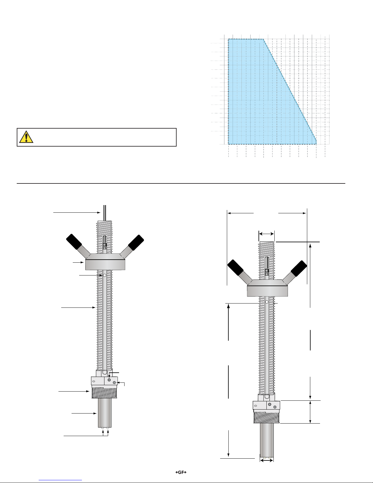
The Signet 2552 Metal Magmeter from Georg Fischer features all-stainless steel construction. The PVDF nosepiece and FPM O-rings
are the only other wetted materials. The 2552 installs quickly into standard 1¼ in. or 1½ in. pipe outlets, and is adjustable to fit pipes
from DN50 to DN2550 (2 to 102 inches). Three sensor lengths allow maximum flexibility to accommodate a variety of hardware
configurations, including ball valves for hot-tap installations.
When equipped with the frequency output, the 2552 is compatible with any Signet flow instrument, while the S3L Digital output enables
multi-channel compatibility with the Signet 8900 Multi-Parameter Flow Controller. Select the blind 4 to 20 mA current output to interface
directly with dataloggers, PLCs or telemetry systems.
Key features include Empty Pipe Detection, LED-assisted troubleshooting, and Bi-Directional span capability (in 4 to 20 mA models).
The Signet 3-0250 USB to Digital (S3L) Configuration/Diagnostic Tool is available to customize every performance feature in the 2552
so it can be adapted to the user's application requirements.
Performance
Pipe size range: DN50 to DN2550 (2 in. to 102 in.)
Flow Range:
• Minimum: 0.05 m/s (0.15 ft/s)
• Maximum: 10 m/s (33 ft/s) for pipes to DN 1200 (48 in.)
3 m/s (10 ft./s) for pipes over DN 1200 (48 in.)
Linearity: ±(1% reading + 0.01 m/s)
±(1% reading + 0.033 ft/s)
Repeatability: ±0.5% of reading @ 25 °C
Accuracy: ±2% of measured value (in reference conditions
where the fluid is water at ambient temperature, the sensor
is inserted at the correct depth and there is a fully developed
flow profile which is in compliance with ISO 7145-1982 (BS
1042 section 2.2))
Minimum Conductivity: 20 S/cm
Wetted Materials
• 316L Stainless Steel body and electrodes
• PVDF Insulator
• O-rings: FPM (standard)
• Cable: 4-cond + shield, PVC jacket (Fixed cable models) or
Water-resistant rubber cable assembly with Turck®NEMA 6P
connector
Power Requirements
• 4 to 20 mA: 24 VDC ± 10%, regulated, 22.1 mA maximum
• Frequency: 5 to 24 VDC ± 10%, regulated, 15 mAmaximum
• Digital (S3L): 5 to 6.5 VDC, 15 mA maximum
• Reverse polarity and short circuit protected
Cable Options
• Fixed 7.6 m (25 ft) cable
• Detachable water tight sensor cable with Turck® connector
sold separately, two lengths: 4m (13 ft) or 6m (19.5 ft)
Custom lengths available, contact Georg Fischer Signet
Electrical
Current Output (4 to 20 mA)
• Programmable and reversible
Factory Range: 4 to 20 mA = 0 to 5 m/s
• Loop Accuracy:
32 A max. error (@ 25 °C @ 24 VDC)
• Temp. drift: ±1 A per °C max.
• Power supply rejection: ±1 A per V
• Isolation: Low voltage < 48 VAC/DC from electrodes and
auxiliary power
• Maximum cable: 300 m (1000 ft)
• Max. Loop Resistance: 300
• Error condition: 22.1 mA
Frequency output
• Compatible with Signet 5075, 5500, 5600, 8550 and 8900
• Max. Pull-up Voltage: 30 VDC
• Short Circuit Protected: 30 V @ 0 pull-up for one hour
• Reverse Polarity Protected to -40 V for 1 hour
• Overvoltage Protected to +40 V for 1 hour
• Max. Current Sink: 50 mA, current limited
• Maximum cable: 300 m (1000 ft)
Digital (S3L) Output
• Compatible with Signet 8900
• Serial ASCII, TTL level 9600 bps
• Maximum cable: Application dependent (See 8900 manual)
Standards and Approvals
• CE
• U.S. Patent No.: 7,055,396 BI
• NEMA 4 (IP65) (fixed cable models)
• NEMA 6P (IP68) (Submersible cable models only)
Signet recommends maximum 3 m. (10 ft) submersion depth
for maximum 10 days continuous submersion.
• Manufactured under ISO 9001 and ISO 14001
China RoHS (Go to www.gfsignet.com for details)

2 2552 Magmeter
2.1 Temperature and Pressure Specifications
Max. Temperature/Pressure Rating
Storage Temperature:
-15 °C to 70 °C (5 °F to 158 °F) in non-icing conditions
Operating Temperature
• Ambient: -15 °C to 70 °C (5 °F to 158 °F) in non-icing conditions
• Media: -15 °C to 85 °C (5 °F to 185 °F)
Maximum Operating Pressure:
20.7 bar @ 25 °C (300 psi @ 77 °F)
Hot-Tap Installation Requirements
• Maximum Installation Pressure: 20.7 bar (300 psi)
• Maximum Installation Temp.: 40 °C (104 °F)
Do not use hot-tap installation where temperatures will
exceed 40 °C or if hazardous liquids are present.
Media Temperature
Operating Pressure
10 100
158 185 212
-10
41
20-20 30405060708090
59 77
°F
°C
5
0
0
0.9
150
175
300
200
225
50
25
2.6
75
100
125
23
250
275
95 113 131
20.6
11.2
7.8
9.5
16.4
bar psi
Safe Media Pressure
and
Temperature Range
14.7
18.1
12.9
4.3
6.0
19.8
2552 Magmeter
Temperature-Pressure Operating Range
Locking
Set Screw
Threaded
Ground lug
A
lignment Reference hole
Process Connector Nut
1¼ in. or 1½ in.
NPT or ISO threads
316 SS Sensor Body
Signal Cable
Sensor Adjustment Hub
A
CME Threaded
outer housing
316 SS Electrodes
41 mm
1.6 in.
137 mm
5.4 in.
2552-2 models
290 mm
11.4 in.
2552-3 models
432 mm
17.0 in.
2552-2 models
276.3 mm
10.88 in.
2552-3 models
419 mm
16.5 in.
32 mm (1.25 in.)
Acme threads
2.3 2552 Magmeter Dimensions
2.2 2552 Magmeter Overview

32552 Magmeter
3. Selecting a Location
The 2552 requires a fully developed turbulent flow profile for accurate measurement. Selecting the correct location in the piping system
is critical to the performance of the magmeter.
Locate the magmeter where air bubbles will not contact the electrodes.
Placing the sensor in a vertical section of pipe, with flow going UPHILL is the first choice for this requirement.
The piping system should be designed to keep the sensor wet at all times.
In applications where the conductivity of the process liquid is less than 100 S, magmeters should be allowed to soak in a full pipe for
24 hours before operation.
3.1 Vertical Installations Recommended
Locating the sensor where the flow is upward protects the sensor from exposure to air bubbles and may offset upstream turbulence
caused by pipe conditions and other hardware.
+GF+
15 x I.D. 5 x I.D.
Reducer
+GF+
10 x I.D. 5 x I.D.
Inlet Outlet
Flange
+GF+
50 x I.D. 5 x I.D.
Valve/Pump
+GF+
40 x I.D. 5 x I.D.
2 x 90° Elbow
3 dimensions
25 x I.D. 5 x I.D.
2 x 90° Elbow
+GF+
20 x I.D. 5 x I.D.
90° Elbow
+GF+
+GF+
O.K.
+GF+
O.K.
+GF+
O.K.
20 x ID
+GF+
+GF+
+GF+
3.2 Horizontal Installations
If the magmeter must be mounted in a horizontal section of pipe, take extra precautions to prevent air bubbles from passing over the
sensor.
Select a location with sufficient distance of straight pipe immediately upstream of the sensor. The dimensions illustrated here are
intended for general guidance. Every piping system has unique characteristics, and requires individual evaluation.
Located the magmeter in a "trap" to prevent air bubbles and to
keep the electrodes wetted for best performance. Air pockets and bubbles will travel at the top of a horizontal pipe,
so avoid vertical installations.
Sediments and debris that collect at the bottom of a horizontal
pipe will interference with the operation.

4 2552 Magmeter
4. General Installation and Grounding Tips
4.1 Sensor conditioning
The Magmeter output signal may be unstable immediately after installation. Allowing the sensor to soak in a full pipe (or in any
container of water) for 24 hours will stabilize the performance.
• Very low conductivity fluids may require a longer conditioning period.
• The Magmeter may not operate properly in fluids where the conductivity is less than 20 μS/cm.
4.2 Grounding
The 2552 Magmeter is unaffected by moderate levels of electrical noise, especially if installed in a properly grounded metal piping
system. However, in some applications it may be necessary to ground portions of the system to eliminate electrical interference. The
grounding requirements will vary with each installation.
One or more of the following steps may be applied if the 2552 Magmeter is affected by electrical noise:
cConnect a wire (14 AWG/2.08 mm2 recommended) from the ground terminal screw on the sensor nut directly to a local Earth
ground.
dInstall fluid grounding devices immediately upstream and downstream of the Magmeter.
Connect the fluid grounds to the Earth ground terminal on the 2552.
Use flanged grounding rings or metal electrodes on plastic pipes, or metal clamps on metal pipes.
Fluid grounds must be in direct contact with the fluid, and as near to the Magmeter as possible.
eConnect the SHIELD conductor to Earth ground near the instrument.
Grounding rings on plastic pipe
(Installed between flanges)
(10 cm to 1.3 m) (10 cm to 1.3 m)
4 in. to 50 in. 4 in. to 50 in.
FLOW →
→
Blue
Black
Brown
White
Shield
3.
Flow6.25GPM
Total 1234567.8>
ENTER
Signet Flow
Transmitter
1.
2. 2.
8550

52552 Magmeter
1. The height from the magmeter electrodes to the alignment rod is:
-2 Versions: 276.3 mm ( 10.88 in. )
-3 Versions: 419.0 mm ( 16.50 in. )
2. Subtract the wall thickness of the pipe:
- Wall Thickness: -_____ mm ( ______ in.)
3. Subtract 10% of the pipe inside diameter:
- 10% of pipe id: -_____ mm ( ______ in.)
4. The result is the H-dimension. Record the result here for reference at the installation site:
= H dimension: =_____ mm ( ______ in.)
H Dimension
10% of
inside diameter
Wall Thickness
Hardware
Stack Height
4.3 Preparing for Installation
The alignment of the electrodes in the pipe and the insertion depth of the electrodes in relation to the inside diameter of the pipe are
critical to the successful operation and calibration of the system. The brass rod that is supplied with the 2552 is used to assist with this
requirement.
4.4 H-Dimension
The H-dimension is the distance from the TOP OF THE PIPE to the BOTTOM OF THE BRASS ROD.
The tables on pages 8–11 include the H-dimension for two of the most common pipe schedules from DN50 to DN2550 (2 in. to 102 in.).
If the pipe is not represented in the tables on pages 8–11, use the procedure below to determine the H-dimension.
The goal of the procedure is to place the Magmeter electrodes 10% inside of the pipe
Hardware stack height is important
The H-dimension represents the total height
avaliable for the installation hardware.
If there is insufficient clearance to accommodate
the hardware, select a longer 2552 Magmeter or
modify the hardware to reduce the stack height.

6 2552 Magmeter
3. Install the Magmeter into the pipe
a. Apply sealing tape or paste to the male threads of the process
connector nut.
b. Tighten the process connector into the pipe.
• Do not damage the locking set screw when using tools.
• The sensor is marked to identify the downstream alignment.
The arrow MUST point DOWNSTREAM.
• Hold the outer sensor housing securely while threading the
process connector nut into the fitting. This will prevent the cable
from becoming twisted around the sensor while the process
connector is tightened into the pipe.
c. Loosen the set screw in the process connector nut.
d. Rotate the Acme threaded outer housing until the flow arrow is
aligned in the proper direction.
e. Secure the set screw sufficiently to prevent the outer housing from
spinning.
Do not tighten the set screw yet. It may require additional
adjustment.
Not supplied with the 2552 Magmeter:
• Female pipe fitting (weld-on or saddle) with:
1¼ in. NPT or ISO 7/Rc 1¼ threads (2552-2)
1½ in. NPT or ISO 7/Rc 1½ threads (2552-3)
• 1¼ in. or 1½ in. ball valve (for hot tap installations)
• 32 mm (1¼ in.) or 40 mm (1½ in.) diameter drill
• Pipe thread sealant suitable for application
• Pipe wrench
• 32 mm (1¼ in.) pipe nipple
• 32 mm (1¼ in.) ball valve
• 32 mm (1¼ in.) drill bit
Supplied with 2552 Magmeter:
• Ruler
• Brass alignment rod
• H-dimension value for your pipe (See pages 6–9)
• Hex wrench
• 2 clamp rings
• Grounding screw
5. Magmeter Installation
The following items are required to properly install the Magmeter:
1. Determine the H-dimension for the pipe.
• The tables on pages 8–11 list the H-dimension metal pipe per ANSI 36.10 and ANSI 36.19.
• Use the procedure on page 5 to determine the H-dimension for other types of pipe.
2. Prepare the pipe:
a. Cut a 32 mm (1¼ in.) opening in the pipe.
b. Install a 1¼ in. (for 2552-1, 2552-2) or 1½ in. (for 2552-3) outlet onto the pipe.
This fitting must withstand pressures up to 20 bar (300 psi).
• For Hot-tap installations:
Thread a matching pipe nipple and ball valve into the outlet.
Use a suitable paste or sealing tape to provide a leakproof connection.
Hot- tap drilling requires special tools and skills.
This task should only be performed by qualified personnel.
FLOW →
FLOW →
FLOW →
FLOW →
FLOW →
FLOW →
Position the ball valve handle so it is parallel to the pipe.
This will prevent the valve handle from interfering with
the adjustment and alignment of the magmeter.
• Remember to tilt the magmeter to avoid air bubbles.
Wear gloves to grip the outer sensor housing.

72552 Magmeter
Pipe Top View
Align Magmeter with pipe ±1°
H
FLOW →
FLOW →
4. Adjust the magmeter position and insertion
depth
a. Insert the brass rod through the alignment reference hole
located directly below the sensor adjustment hub.
b. Adjust the height of the magmeter by turning the sensor
adjustment hub clockwise until the distance from the
OUTSIDE of the pipe to the bottom of the alignment rod is
equal to the H-dimension (as recorded on pg. 5).
• Installation tip: If necessary, apply a suitable lubricant to
the Acme threads to facilitate smooth operation.
5. Secure the Magmeter in position
• Secure the height adjustment by installing the two pipe clamps
above and below the sensor adjustment hub.
• Spread the clamp apart to wrap it around the outer
housing.
• Place one clamp immediately above and one clamp
immediately below the magmeter adjustment hub.
• Squeeze the clamp together until it is firmly locked around
the housing.
Set Screw
Set Screw
Wrench
FLOW →
The distance from the
OUTSIDE of the pipe
to the bottom of the
alignment rod must be
equal to the H-dimension
c. Loosen the locking set screw and rotate the outer housing
to align the brass rod with the centerline if the pipe.
d. When the magmeter is adjusted for the proper height and
alignment, tighten the locking set screw firmly.
CAUTION: Overtightening the set screw may damage the
hex key.
6. Removal Instructions for Hot-tap Installations
REDUCE THE PROCESS TEMPERATURE TO LESS THAN 40 °C (104 °F)
REDUCE THE SYSTEM PRESSURE TO A SAFE LEVEL.
WEAR SUITABLE PROTECTIVE EQUIPMENT WHEN WORKING WITH
PRESSURIZED PIPES.
• Remove the steel clamp from the top of the assembly.
• Turn the sensor adjustment hub counter-clockwise until the sensor is fully
retracted. (The alignment sensor hole should be at the top of the outer housing slot.)
Apply a suitable lubricant to the ACME threads to ease the retraction.
• Close the valve after raising the magmeter to the top of the housing.
Install a LOCKOUT TAG on the closed valve to prevent accidents!
• Remove the magmeter from the top of the valve.
• Loosen the locking set screw on the process connector nut.
• Use one pipe wrench to hold the valve in place while turning the process connector
nut with a second wrench.
• Do not damage the locking set screw when using tools.
UNDER PRESSURE!
HOLD VALVE IN PLACE!
Turn magmeter adapter ONLY!
CLOSE VALVE
BEFORE REMOVING MAGMETER!
DANGER!
DO NOT
DO NOT
OPEN
OPEN
THIS VALVE
THIS VALVE
This lock/tag may
only be removed by:
Name ___________
Dept. ____________
Expected date for
completion:_________

8 2552 Magmeter
• The 2552 outputs an open collector frequency signal that
can be connected to any powered Signet flow meter. (Models
5075, 5500, 5600, 8550, 8900.)
• DC power is provided to the 2552 Magmeter by all Signet
flow instruments. No additional power is required.
• If connecting the 2552 Magmeter to a flow instrument from
another manufacturer, 5 to 24 VDC power must be provided
to the 2552. A 10 KΩpull up resistor must also be connected
between the +V (Black) and the Freq. Out (Red) wires.
• ALWAYS connect AUX power on the 8550 to provide power
for the 2552 output signal.
6.1 Wiring: Frequency output (Compatible with all POWERED Signet Flow instruments.)
6.2 Wiring: 8900 Multi-Parameter Controller
6. Wiring the 3-2552-XX-11 with Frequency or Digital (S3L) output
3-8900.621C
I/O Module 3-8900.401-X 1
2
3
4
5
6
7
8
9
10
11
12
13
14
+5VDC (Black)
Freq. Input (Red)
GND (Shield)
+5VDC (Black)
Freq. Input 2 (Red)
S L (Red)
GND (White/Shield)
+5VDC (Black)
S L (Red)
GND (White/Shield)
3
3
Analog Output 1
Analog Output 2
(if applicable)
(if applicable)
Frequency
Input
1
Frequency
Input 2
OR
S3L
Input
2
S3L
Input
1
+
-
+
-
White
Blue
Brown
Black
Shield
8900 S L Wiring
3
3-8900.621C
I/O Module 3-8900.401-X
1
2
3
4
5
6
7
8
+5VDC (Black)
Freq. Input (Red)
GND (Shield)
+5VDC (Black)
Freq. Input 2 (Red)
S L (Red)
3
Frequency
Input
1
Frequency
Input 2
OR
S3L
Input
2
White
Blue
Brown
Black
8900 Frequency Wiring
Shield
• The 2552 receives 5 VDC power from the 8900.
No additional power is required.
6.3 Wiring the 2552-XX-12 Magmeter with 4 to 20 mA Loop Output
The 2552 Magmeter is a traditional 2-wire passive 4 to 20 mA loop transmitter.
• External loop power (21.6 to 26.4 VDC, 22.1 mA maximum)
is required. (See Power Requirements on pg. 1)
The maximum loop resistance the Magmeter can
accomodate is 300 Ω.
The cable length from the Magmeter to the loop monitor
cannot exceed 300 m (1000 ft).
• All 2552 Magmeters are shipped from the factory with the 4
to 20 mA output scaled for 0 to 5 m/s (0 to 16.4 ft/s). If this
operating range is suitable, no adjustments are necessary.
The calibration charts in this manual list the 20 mA setpoint
for each pipe size. Use this information to program the 4 to
20 mA range of the loop device (PLC, Datalogger, recorder,
etc.).
2552 Magmeter
4 to 20 mA Loop
monitor
(Maximum 300 Ω)
+
+
-
-
24 VDC ± 10%
Brown X
Blue X
White
Loop - (Ground)
Black Loop + (24 VDC)
NOTE:
The maximum cable length from the 2552 to the 8900 depends on the 8900
configuration. Refer to the 8900 manual for complete information.
8550-1 Flow Transmitter
White
Blue
Brown
Black
9
8
7
Sensr IN
(RED)
Sensr V+
(BLACK)
Sensr Gnd
(SHIELD)
Shield
White
Blue
Brown
Black
Shield
Freq. IN
Sen. Pwr.
Freq. IN
Iso. Gnd
Signet 5500
5-24 VDC
S
ensor Ground
Frequency Out
10 KΩ
Install a pull-up resistor when
connecting the 2552 Magmeter
to other manufacturer's flowmeters.
White
Blue
Brown
Black
Non-Signet Instrument
Shield

92552 Magmeter
7. Calibration Data
7.1 K-factors and Full Scale Current Values for 3-2552-2x - x - xx and 3-2552-3x - x - xx Magmeters
Pipe Size (ANSI)
Schedule
OD (Inches)
WALL (Inches)
ID (Inches)
H Dim
-2 Version
H Dim mm
-3X Version
K-Factor
Pulse/liter
K-Factor
Pulse/Gal
Factory set
20 mA (liter/min)
Factory set20
mA (GPM)
Inch mm Inch mm
240 2.375 0.15 2.07 10 16/32 267.0 16 5/32 409.9 46.19 174.83 649.5 171.6
80 2.375 0.22 1.94 10 15/32 265.9 16 3/32 408.6 52.49 198.68 571.5 151.0
2½ 40 2.875 0.20 2.47 10 14/32 264.9 16 407.7 32.37 122.54 926.7 244.8
80 2.875 0.28 2.32 10 12/32 263.4 16 406.2 36.57 138.42 820.3 216.7
340 3.500 0.22 3.07 10 12/32 263.1 15 31/32 405.8 20.97 79.36 1431 378.0
80 3.500 0.30 2.90 10 9/32 261.4 15 29/32 404.1 23.47 88.82 1278 337.8
3½ 40 4.000 0.23 3.55 10 10/32 261.6 15 29/32 404.4 15.68 59.34 1914 505.6
80 4.000 0.32 3.36 10 8/32 259.7 15 27/32 402.5 17.44 66.01 1720 454.5
440 4.500 0.24 4.03 10 8/32 260.1 15 28/32 402.9 12.18 46.09 2464 651.0
80 4.500 0.34 3.83 10 5/32 258.1 15 25/32 400.9 13.48 51.03 2225 587.9
540 5.563 0.26 5.05 10 4/32 257.0 15 24/32 399.7 7.748 29.33 3872 1023
80 5.563 0.38 4.81 10 254.6 15 21/32 397.4 8.519 32.25 3521 930.4
640 6.625 0.28 6.07 10 253.8 15 20/32 396.6 5.365 20.31 5591 1477
80 6.625 0.43 5.76 9 28/32 250.8 15 16/32 393.5 5.946 22.51 5045 1333
840 8.625 0.32 7.98 9 24/32 247.9 15 12/32 390.7 3.098 11.73 9683 2558
80 8.625 0.50 7.63 9 20/32 244.3 15 8/32 387.0 3.394 12.85 8838 2335
10 40 10.75 0.37 10.0 9 16/32 241.6 15 4/32 384.4 1.966 7.440 15262 4032
80 10.75 0.59 9.56 9 11/32 237.00 14 30/32 379.8 2.158 8.170 13899 3672
12 STD 12.75 0.38 12.0 9 10/32 236.4 14 30/32 379.1 1.371 5.187 21890 5783
XHY 12.75 0.50 11.8 9 6/32 233.8 14 26/32 376.6 1.429 5.410 20987 5545
14 30 14.00 0.38 13.3 9 6/32 233.2 14 26/32 375.9 1.124 4.255 26688 7051
XHY 14.00 0.50 13.0 9 3/32 230.6 14 22/32 373.4 1.168 4.420 25690 6787
16 30 16.00 0.38 15.3 9228.1 14 19/32 370.8 0.849 3.212 35352 9340
40/XHY 16.00 0.50 15.0 8 28/32 225.6 14 16/32 368.3 0.877 3.320 34202 9036
18 STD 18.00 0.38 17.3 8 25/32 223.0 14 13/32 365.8 0.663 2.510 45233 11950
XHY 18.00 0.50 17.0 8 22/32 220.5 14 10/32 363.2 0.683 2.585 43931 11610
20 20/STD 20.00 0.38 19.3 8 19/32 217.9 14 6/32 360.7 0.533 2.016 56330 14880
30/XHY 20.00 0.50 19.0 8 16/32 215.39 14 3/32 358.1 0.547 2.069 54876 14500
22 20/STD 22.00 0.38 21.3 8 12/32 212.85 14 355.6 0.437 1.654 68643 18136
30/XHY 22.00 0.50 21.0 8 9/32 210.31 13 29/32 353.1 0.448 1.694 67037 17711
24 20/STD 24.00 0.38 23.3 8 6/32 207.77 13 26/32 350.5 0.365 1.382 82172 21710
XHY 24.00 0.50 23.0 8 3/32 205.23 13 22/32 348.0 0.373 1.412 80414 21246
The data in these tables is based on dimensions of metal pipe per ANSI 36.10 and ANSI 36.19.
Stainless steel and carbon steel pipe schedules have the same dimensions according to ANSI standards.
Contact the local Georg Fischer Signet distributor for assistance with pipe sizes and materials not listed.

10 2552 Magmeter
Pipe Size (ANSI)
Schedule
OD (Inches)
WALL (Inches)
ID (Inches)
H Dim
-2 Version
H Dim mm
-3X Version
K-Factor
Pulse/liter
K-Factor
Pulse/Gal
Factory set
20 mA (liter/min)
Factory set20 mA
(GPM)
Inch mm Inch mm
26 STD 26 0.38 25.25 8 202.69 13 19/32 345.4 0.310 1.172 96917 25606
20/XHY 26 0.50 25.00 7 28/32 200.15 13 16/32 342.9 0.316 1.195 95008 25101
28 STD 28 0.38 27.25 7 25/32 197.61 13 13/32 340.4 0.266 1.006 112879 29823
20/XHY 28 0.50 27.00 7 22/32 195.07 13 10/32 337.8 0.271 1.025 110817 29278
30 STD 30 0.38 29.25 7 19/32 192.53 13 6/32 335.3 0.231 0.873 130056 34361
20/XHY 30 0.50 29.00 7 16/32 189.99 13 3/32 332.7 0.235 0.888 127842 33776
32 STD 32 0.38 31.25 7 12/32 187.45 13 330.2 0.202 0.765 148449 39220
20/XHY 32 0.50 31.00 7 9/32 184.91 12 29/32 327.7 0.205 0.777 146084 38595
34 STD 34 0.38 33.25 7 6/32 182.37 12 26/32 325.1 0.179 0.676 168059 44401
20/XHY 34 0.50 33.00 7 3/32 179.83 12 22/32 322.6 0.181 0.686 165541 43736
36 STD 36 0.38 35.25 7 177.29 12 19/32 320.0 0.159 0.601 188885 49903
20/XHY 36 0.50 35.00 6 28/32 174.75 12 16/32 317.5 0.161 0.610 186215 49198
38 STD 38 0.38 37.25 6 25/32 172.21 12 13/32 315.0 0.142 0.538 210926 55727
XHY 38 0.50 37.00 6 22/32 169.67 12 10/32 312.4 0.144 0.546 208105 54981
40 STD 40 0.38 39.25 6 19/32 167.13 12 6/32 309.9 0.128 0.485 234184 61872
XHY 40 0.50 39.00 6 16/32 164.59 12 3/32 307.3 0.130 0.491 231210 61086
42 STD 42 0.38 41.25 6 12/32 162.05 12 304.8 0.116 0.439 258658 68338
XHY 42 0.50 41.00 6 9/32 159.51 11 29/32 302.3 0.117 0.444 255532 67512
48 STD 48 0.38 47.25 5 25/32 146.81 11 13/32 289.6 0.088 0.335 339377 89664
XHY 48 0.50 47.00 5 22/32 144.27 10 26/32 274.32 0.089 0.338 335795 88717
54 STD 54.00 0.38 53.25 5 6/32 131.57 10 22/32 271.78 0.07 0.2634 431040 113881
XHY 54.00 0.50 53.00 5 3/32 129.03 10 6/32 259.08 0.06 0.2659 427002 112814
60 STD 60.00 0.38 59.25 4 19/32 116.33 10 3/32 256.54 0.06 0.2128 533648 140990
XHY 60.00 0.50 59.00 4 16/32 113.79 9 19/32 243.84 0.06 0.2146 529154 139802
66 STD 66.00 0.38 65.25 4 101.09 9 16/32 241.30 0.05 0.1754 647201 170991
XHY 66.00 0.50 65.00 3 29/32 98.55 9 228.60 0.05 0.1768 642251 169683
72 STD 72.00 0.38 71.25 3 13/32 85.85 8 29/32 226.06 0.04 0.1471 771699 203883
XHY 72.00 0.50 71.00 3 10/32 83.31 8 13/32 213.36 0.04 0.1482 766293 202455
78 STD 78.00 0.38 77.25 2 26/32 70.61 8 10/32 210.82 0.03 0.1252 907141 239667
XHY 78.00 0.50 77.00 2 22/32 68.07 7 26/32 198.12 0.03 0.1260 901280 238119
84 STD 84.00 0.38 83.25 2 6/32 55.37 7 22/32 195.58 0.03 0.1078 1053529 278343
XHY 84.00 0.50 83.00 2 3/32 52.83 7 6/32 182.88 0.03 0.1084 1047211 276674
90 STD 90.00 0.375 89.25 1 19/32 40.13 7 3/32 180.34 0.02 0.0938 1210862 319910
XHY 90.00 0.500 89.00 1 16/32 37.59 6 19/32 167.64 0.02 0.0943 1204087 318120
96 STD 96.00 0.375 95.25 1 24.89 6 16/32 165.10 0.02 0.0823 1379139 364369
XHY 96.00 0.500 95.00 29/32 22.35 6 152.40 0.02 0.0828 1371909 362459
102 STD 102.00 0.38 101.25 13/32 9.65 5 29/32 149.86 0.02 0.0729 1558362 411720
XHY 102.00 0.50 101.00 10/32 7.11 10/32 7.11 0.02 0.0732 1550676 409690
7.1 K-factors and Full Scale Current Values for 3-2552-2x - x - xx and 3-2552-3x - x - xx Magmeters
The data in these tables is based on dimensions of metal pipe per ANSI 36.10 and ANSI 36.19.
Stainless steel and carbon steel pipe schedules have the same dimensions according to ANSI standards.
Contact the local Georg Fischer Signet distributor for assistance with pipe sizes and materials not listed.

112552 Magmeter
8.1 Bi-Directional Flow
The 2552 magmeter is designed to measure bi-directional flow.
• 4 to 20 mA output models: May be scaled to span any
flow range:
For example: "4 to 20 mA = -100 GPM to +100 GPM"
• Frequency output models: The 2552 will generate
a frequency regardless of flow direction. Signet
instrumentation cannot distinguish bi-directional flow from
frequency inputs.
• Digital (S3L) output models: Reverse flow results in 0
flow rate displayed on the 8900 Multi-Parameter Controller.
• The forward flow direction is indicated at the base of the
sensor. The arrow must point DOWNSTREAM.
FLOW→
8.2 USB to Digital (S3L) Configuration/Diagnostic Tool
No calibration is necessary to begin using the 2552.
The application and performance settings are selected by the factory to meet the requirements of most applications.
The 2552 application and performance settings can be customized using the 3-0250 USB to Digital (S3L) Configuration/
Diagnostic Tool.
The following parameters can be modified with the 3-0250 USB Setup tool and software. A Windows PC is required:
• 4 to 20 mA span: Factory setting is 0 to 5 m/s.
Can be customized to any range, including bi-directional flow ranges, ±10 m/s maximum.
• Noise Rejection Filter: Factory set for 60 Hz.
Can be changed to 50 Hz.
• Low Flow Cutoff: Factory setting is 0.05 m/s.
Can be increased to meet specific application requirements.
• Averaging Time:Factory setting is 14 seconds
Can be customized from 0.1 seconds to 100 seconds
• Sensitivity: Factory setting is 25% of full scale
Can be customized to any % of full scale
The MONITOR/VERIFY SENSOR function in the Signet 3-0250
Setup Tool software is very useful as a system troubleshooting
tool.
8.2.1 MONITOR/VERIFY SENSOR
8. Technical Support Information

12 2552 Magmeter
• Conductivity is less than 20 S/cm.
• Electrical noise
• Electronic component failure.
• 4 to 20 mA is not scaled same as
Loop device.
• Loop device is not scaled same as
Magmeter.
• Defective Magmeter
• Magmeter installed too close to
upstream obstruction.
• Magmeter electrodes are coated.
• Magmeter electrodes exposed to air
bubbles/pockets.
• Electrical noise is interfering with the
measurement.
• New sensor, metal surface not
properly conditioned.
• Output is not 0 when flow is stopped.
• Frequency, Digital or Current
output is erratic.
• Output is 22.1 mA.
• Electrodes not adequately conditioned.
• Flow rate is less than Low flow cutoff
value.
• Electrical noise is interfering with the
measurement.
• Defective Magmeter
Symptom Possible Cause Possible Solution
• Frequency output is inoperative
• Digital (S3L) output is inoperative.
• Loop output is inoperative.
• Move the Magmeter upstream at least
10 pipe diameters from obstruction.
• Clean the electrodes with soft cloth.
Do not use abrasives.
• Eliminate air bubbles in the pipe.
• Remove the Magmeter and reinstall
with the flow direction arrow on the
sensor body pointed DOWNSTREAM.
• Modify grounding as required
to protect the Magmeter from
interference.
• Soak sensor overnight in fluid.
8.4 Troubleshooting Table
• Soak sensor overnight in fluid.
• Configure pipe so electrodes are
always in fluid.
• Modify grounding as required
to protect the Magmeter from
interference.
• Adjust low flow cutoff higher.
• Return to factory for service.
• Use 3-0250 Span and Setup tool to
set output range.
• Respan Loop device to match
Magmeter.
• Return to factory for service.
• 2552 is wrong model.
• Wiring is not correct.
• Frequency input to other
manufacturer's flow instrument does
not have pull-up resistor.
• Freq/S3L model is 3-2552-XX-11.
• Blue wire must be grounded for freq
out, open for S3L out.
• 4 to 20 mA model is 3-2552-XX-12.
• Check wiring, make corrections.
• Install 10kΩresistor.
• Unsuitable application for Magmeter.
• Check grounding, eliminate noise
source
• Return to factory for service.
• 4 to 20 mA output is incorrect.
8.3 Troubleshooting with the RED and BLUE lights
The 2552 uses two colored LEDs to indicate the status of the measurement. They are located at the top of the magmeter, recessed
inside the threaded steel housing. Look down the outer housing to see them.
No Lights: The power is off or the sensor is not connected
Solid Blue: The power is on but there is no flow in the pipe.
Blinking Blue: Normal operation, blink rate is proportional to the flow rate.
Alternating Red-Blue: Empty pipe indication (electrodes are not wet.)
Blinking Red: System errors (Generally indicates electrical noise interference)
Solid Red: Instrument error (Generally indicates defective electronics component)
The lights are for troubleshooting guidance only and are not absolute fault indicators.
B
l
u
e
R
e
d
Environmental Recommendations:
• When used properly, this product presents no inherent danger to the environment.
• Please follow all appropriate local ordinances when disposing of this or any product with electronic components.
8.5 Maintenance
There are no user-serviceable components in the Magmeter.
• If the fluid contains deposits and solids that may coat the electrodes, a regular cleaning schedule is recommended.
• Do not use abrasive materials on the metal electrodes. Clean with soft cloth and mild detergent only.
• Use a cotton swab and mild detergent to remove deposits on the metal electrodes at the tip of the sensor.
• If the sensor nut will not turn smoothly, a light lubricant can be applied to the threads.

132552 Magmeter
Sensor Selection Guide
The 2552 Magmeter can be installed into a variety of pipe sizes. Follow the steps below
to ensure that you choose the right sensor for your application.
Step 1: Determine how the sensor will be installed
• For retrofit installations, the ball valve
must be at least a 1¼ in. (or 1½ in.
for 2552-3) full port valve. The stack
height, or “A” dimension (see Fig. 2), is
the overall height from the top of the
pipe to the top of the ball valve, or the
top of the highest point of the stack
before the sensor is connected.
B. For Hot-Tap installations:
The stack height of the ball valve, nipple weldolet (threadolet) and pipe adapters should
be determined before the sensor is purchased.
• For new installations, Signet
recommends a 1¼ in. or 1½ in. full
port ball valve, a short nipple and
a weldolet (threadolet). The stack
height or “A” dimension (see Fig. 2) is
the overall height from the top of the
pipe to the top of the ball valve.
A. For standard (non Hot-Tap) installations:
The height of the weldolet (threadolet) and pipe adapter(s) should be determined before
the sensor is purchased.
• For retrofit installations, the stack
height, or “A” dimension (see Fig. 1), is
the overall height from the top of the
pipe to the highest point of the stack
before the sensor is connected.
• For new installations, Signet
recommends a weldolet (threadolet)
and an adapter to accommodate the
1¼ in. (or 1½ in. for 2552-3) sensor
process threads. The stack height,
or “A” dimension (see Fig. 1), is the
overall height from the top of the pipe
to the highest point of the stack.
Step 2: Determine how the sensor will be installed
Once the “A” dimension is determined, go to the sensor selection table and find your “A”
dimension on the left column. Next, find the appropriate pipe size at the top of the chart.
To determine the correct sensor size locate where the pipe size column meets the max
“A” dimension row.
“A”
Dimension
Weldolet
or Saddle
Sensor
Housing
Sensor
Fig. 1
Standard installation with “A”
dimension using a weldolet
(threadolet)
“A”
Dimension
Weldolet
Nipple
Ball
Valve
Pipe
Wall
Sensor
Housing
Sensor
Fig. 2
Hot-Tap installation with “A”
dimension using a ball valve,
short nipple and weldolet
(threadolet)
Step 3: Refer to Ordering Information to select corresponding part numbers
Legend:
2: Use 3-2552-2,
max. insertion =
236 mm (9.3 in.)
3: Use 3-2552-3
max. insertion =
368 mm (14.8 in)
inches
2
2.5
3 to 31/2"
4
5
6 to 8"
10
12 to 14"
16
18
20
22
24
26 to 28"
30 to 32"
34
36 to 38"
40 to 42"
48
54
60
66
72
78
84
102
DN
50
65
80 to 90
100
125
150 to 200
250
300 to 350
400
450
500
550
600
650 to 700
750 to 800
850
900 to 950
1000 to 1100
1200
1400
1500
1700
1800
2000
2100
2550
mm inches
50.8 2 22222222222222222223333333
63.5 2.5 22222222222222222223333333
76.2 3 22222222222222222223333333
88.9 3.5 22222222222222222223333333
101.6 4 22222222222222222223333333
114.3 4.5 2222222222222222223333333
127 5 2222222222222222233333333
139.7 5.5 2222222222223223333333333
152.4 6 2222222222233233333333333
165.1 6.5 222222222333333333333333
177.8 7 22222223333333333333333
190.5 7.5 2222222333333333333333
228.6 9 23333333333333333333
241.3 9.5 3333333333333333333
254 10 333333333333333333
266.7 10.5 33333333333333333
279.4 11 333333333333 333
292.1 11.5 33333333333 3
304.8 12 3333333333
317.5 12.5 33333333
330.2 13 3333333
342.9 13.5 333333
355.6 14 33333
375.9 14.8 3 3
381 15
Pipe Size
Max. "A" Dim
This chart is based on the thickest commonly available pipe.

14 2552 Magmeter
Notes:

152552 Magmeter
Notes:

Georg Fischer Signet LLC, 3401 Aerojet Avenue, El Monte, CA 91731-2882 U.S.A. • Tel. (626) 571-2770 • Fax (626) 573-2057
For Worldwide Sales and Service, visit our website: www.gfsignet.com • Or call (in the U.S.): (800) 854-4090
For the most up-to-date information, please refer to our website at www.gfsignet.comw
3-2552.090 Rev. E 07/10 English © Georg Fischer Signet LLC 2010
Ordering Information
Model 2552 Metal Magmeter Ordering Matrix
3-2552 Mounting Depth Options - Choose One*
-2 Sensor insertion depth = 9.3 inches*
-3 Sensor insertion depth = 14.8 inches*
Process Connection Options - Choose One
11¼ inch NPT Process Connection Threads**
21¼ inch ISO Process Connection Threads**
31½ inch (2552-3 only) NPT Process Connection Threads**
41½ inch (2552-3 only) ISO Process Connection Threads**
Cable and Connector Options - Choose One
-A Fixed Cable, 7.6m (25 ft); no connector
-B Watertight sensor connector; cable sold separately
Output options - Choose One
-11 Frequency or Digital (S3L); for use with any
Signet Flow Instrument or the 8900 Multi-
Parameter Controller
-12 4 to 20 mA output
3-2552 -2 1 -A -12 Example Part Number
* Customer must determine stack height (ball valve, nipple, weldolet, etc.). Refer to
Sensor Selection on previous page to determine “A” dimension.
** 1¼ inch process connection is the standard thread size on the 2552: For the 2552-3
the 1½ inch process connection is standard and the 1¼ inch is available as a special
order.
Model 2552
Ordering Notes:
1) Sensor insertion depth
is the distance from the
bottom of the sensor
housing to the tip of the
sensor.
2) Hot-Tap installations
require a 1¼ in. or 1½ in.
ball valve.
3) See Sensor Selection
Guide on previous page
to determine the sensor
length required.
Accessories and Replacement Parts
Application Tips:
• Minimum process liquid
conductivity requirement
is 20μS/cm.
• 1½ inch and 2 inch
(2552-2 only) retrofit
adapters are available
for replacement
installations of Signet
2550 and 2540 sensors.
Mfr. Part No. Code Mfr. Part No. Code
3-2552-21-A-11 159 001 513 3-2552-33-A-11 159 001 521
3-2552-21-A-12 159 001 514 3-2552-33-A-12 159 001 525
3-2552-21-B-11 159 001 515 3-2552-33-B-11 159 001 523
3-2552-21-B-12 159 001 516 3-2552-33-B-12 159 001 527
3-2552-22-A-11 159 001 517 3-2552-34-A-11 159 001 522
3-2552-22-A-12 159 001 518 3-2552-34-A-12 159 001 526
3-2552-22-B-11 159 001 519 3-2552-34-B-11 159 001 524
3-2552-22-B-12 159 001 520 3-2552-34-B-12 159 001 528
Mfr. Part No. Code Description
2120-1512 159 001 425 1½ x 1¼ inch NPT adapter for retrofitting 2540 installation to 2552 -
316 stainless steel
2120-2012 159 001 426 2 x 1¼ inch NPT adapter for retrofitting 2550 installation to 2552 -
316 stainless steel
3-2552.392 159 001 530 1¼ inch NPT full port stainless steel ball valve and nipple kit
3-2552.393 159 001 531 1¼ inch NPT full port brass ball valve & nipple kit
3-2552.394 159 001 532 1½ inch NPT conduit adapter, aluminum
4301-2125 159 001 533 1¼ inch NPT full port ball valve - brass
4301-3125 159 001 387 1¼ inch NPT full port ball valve - stainless steel
3-0250 159 001 538 USB to Digital (S3L) configuration/diagnostic tool
5541-4184 159 001 388 4-conductor, 22 AWG, water-tight connector, 4m (13 ft)
5541-4186 159 001 389 4-conductor, 22 AWG, water-tight connector, 6m (19.5 ft)
special order special order 4-conductor, 22 AWG, water-tight connector, cable length in 25 ft increments
special order special order 1¼ in. NPT or ISO Process Connection threads to replace 1½ in. NPT or ISO threads
Table of contents
Other Georg Fischer Measuring Instrument manuals