6159938000-07
English
8 / 98
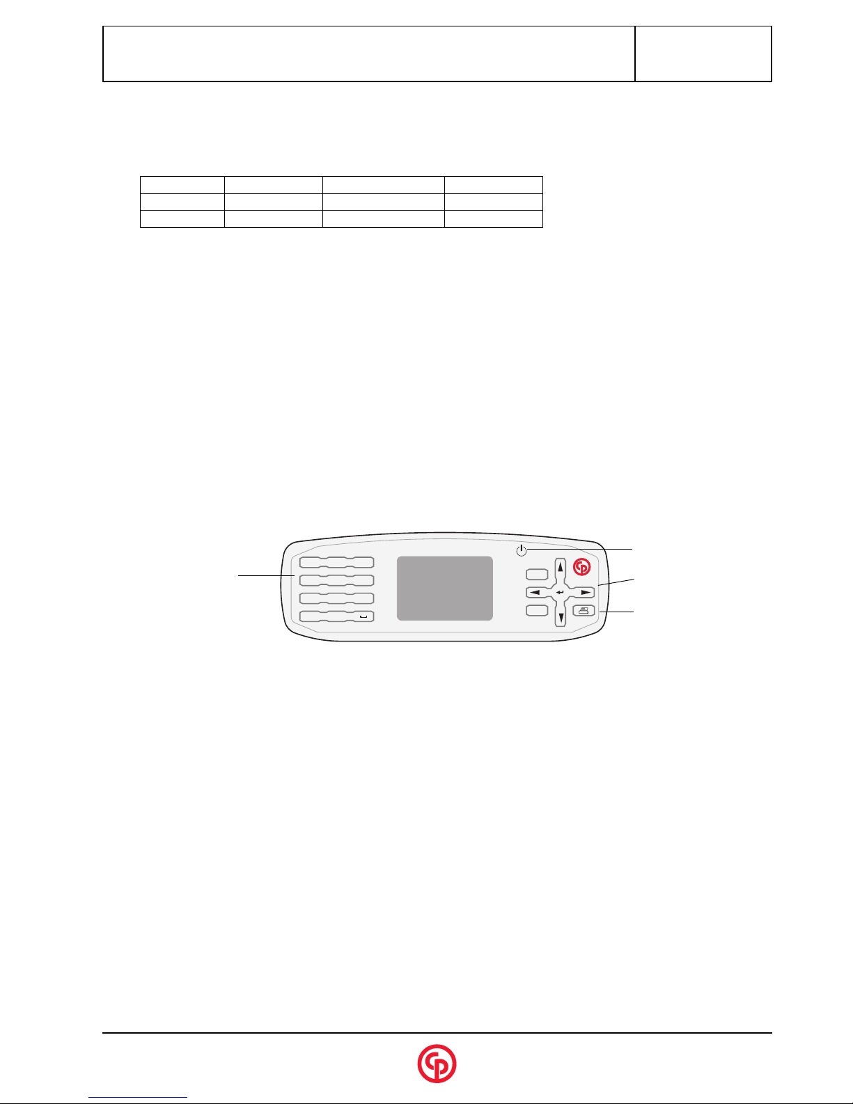
SIGMA2001/2D
Transducer connection:
The transducers that may be connected to this measuring unit are the CMD** series analog transducers or the DRT series
digital transducers. DRT type transducers are automatically recognised by the measuring unit, and their characteristics are
automatically taken into account.
The selection of a transducer type is determined by the selection of a task in the measurement screen; several cases can be
considered if the transducer determined by the task is not identical to the transducer actually connected.
Conformity between the task-oriented transducer and the transducer actually connected, is continuously checked on the
measurement screen, in order to take account of a change even if made with the transducer switched on.
** SIGMA 2001 only
4 - "PARAMETERS" MENU
To exit the "Acquisition" menu, press ¡. The main menu is displayed.
This menu allows the operator to program the parameters of the task, parallel printer and serial link.
Note: The unit can be reset (erasing all parameters and measurements) by pressing ¥when switching on.
4.1 - "Task" menu
Automatic Reset principle:
The system starts a measurement as soon as the value is higher than the programmed measurement threshold. The
system detects when the torque drops below the Reset threshold (x% of the peak value), checks that the value does not
rise during a time period equal to the programmed time then saves the measurement. The display is not reset
immediately. When the system detects that the torque rises again, the previous measurement is erased.
Note: if the value rises again above the "measurement threshold" during the resetting time, the measurement is not
completed and therefore not saved.
Note: in "hydro" mode, the measurement is considered to be completed when no torque value has risen above the
measurement threshold for a time interval which can be programmed in the "auto reset time" parameter. This means
that this time interval must be higher than the one measured between 2 peaks.
In Automatic Reset:
Threshold Reset Threshold: 50% by default
Transducer connected Task-oriented transducer Action
DRT4xx or DRT5xx Other DRT transducer or ana-
log transducer of CMDxx type,
etc.
The transducer normally provided for this task is
replaced by the transducer connected, after validation
by the operator.
Analog transducer (no digital
transducer detected)
DRTxx Prohibit measurement
Locking warning message (no transducer connected)
Analog transducer (no digital
transducer detected)
Analog transducer OK
Digital transducer DRTxx Same transducer DRTxx OK
Name 10 alphanumerical characters as a maximum.
Mode the acquisition mode is selected according to the type of tool being checked:
• Standard mode
• Hydro mode, designed for reading the torque of pneumatic oil pulse wrenches.
Bw 16, 128, 512, 1024 or 2048 Hz (for the standard mode).
Transducer type of torque transducer. Press "1" to display the submenu.
Unit Nm/N.cm/Kg.cm/Ft.Lb/In.Lb/N/dN/kN/Kg.
N. Meas. number of measurements between 1 and 1000.
Th. measurement Threshold (absolute value in the unit selected).
Reset automatic/manual reset