Testec TT-AF 1200 User manual

INSTRUCTION MANUAL
TT
-AF
1200
Ac
tive Oscilloscope FET-P
robe
1,2 GHz / 10:1


1.
Sa
ety Te
r
ms and Symbols
T
e
r
ms appear in this manual:
___________________________________________________
W
ARN
IN
G. Warning statements identify conditions or practice that
co ld res lt in inj ry or loss life.
___________________________________________________
CAUTION. Ca tion statements identify conditions or practice that
co ld res lt in damage to this prod ct or other property.
These probe is in compliance with
EN61010-031
CAT I, Pollution Degree 2
Connect it to sa ety earth ground using the wire recommended in
the user’s manual.
High voltage danger
The symbol on an instrument indicates that the user should re er
to the operating instructions located in the manual.
S
a
e
t
y
S
y
m
b
o
l
s

2. General Sa ety Summary
Review the following safety preca tions to avoid inj ry and prevent damage to this probe or
any prod cts that connected to it.
O
b
serve Maxi
mum Working
Voltage
To avoid any inj ry, do not se the probe nder the condition that the voltage between
either inp t head or earth is above ± 40V (DC
+ peak AC).
Must be Grounded
This probe is gro nded with the shell of BNC connector, thro gh the gro nding cond ctor of
the power cord of the meas rement instr ment. Before making connections to the inp t
leads of this probe, ens re that the o tp t BNC connector is attached to the BNC connector
of the meas rement instr ment, while the probe is properly gro nded.
Do Not Operate Without Covers
To avoid electric shock or fire hazard, do not operate this probe with covers removed.
Do Not Operate in Wet/Damp Conditions
To avoid electric shock, do not operate this probe in wet of damp conditions.
Do Not Operate in Explosive Atmosphere
To avoid inj ry or fire hazard, do not operate this probe in an explosive atmosphere.
Avoid Exposed Circuit
To avoid inj ry, remove jewelry s ch as rings, watches, and other metallic objects. Do not
to ch exposed connections and components when power is present.
Use Proper Power Source
To ens re this probe f nction well, se one 9V battery or mains adapter with 5VDC/200mA
or 9VDC/150mA. The probe also can be powered by different power leads. Do not operate
this probe from a power so rce that applies more than the voltage specified.
Do Not Operated With Suspected Failures
If yo s spect there is damage to this probe, have it inspected by q alified service
personnel.
Cleaning
Use a soft cloth to clean the dirt. Prevent damage to probe. Avoid immersing the probe.
Avoid sing abrasive cleaners. Avoid sing chemicals contains benzene or similar solvents.

3. Description
4. Installation
With high bandwidth, this active 10:1 probe is ideal for timing analysis or tro bleshooting of
high speed logic and for design verification of disk drive, as well as for wireless and data
comm nication design.
a. Simply pl g-in the BNC o tp t connector to the vertical inp t of an oscilloscope
or other meas rement instr ment with 50Ohm inp t resistance.
The instr ment m st have a gro nd reference.
b. Connect an appropriate power so rce to this probe or enter the batteries, then t rn it on.
c. To se the probe with batteries, first slide open the battery compartment on the rear of
the probe ho sing and insert the 9V battery
d. Yo can also se the s pplied mains adapter or the optional USB-, PROBUS
or LEMO-power leads.
WARNING To protect against electric shock, se only the
accessories s pplied with this probe or the optional
offered TESTEC accessories.
Using the appropriate probe accessories, connect the inp ts to the circ its nder
meas rement.
CAUTION. This probe is to carry o t meas rement
between two points on the circ it nder meas rement.
This probe is not for electrically ins lating the circ it
nder meas rement and the meas ring instr ment.

5. Appearance
The active probe looks as follows.
a. Inp t Pins the inp t pins of the active probe can be connected directly
to the circ it nder test or connected to the accessories that
come with the probe.
b. O tp t cable the BNC o tp t connector connected to the oscilloscope
c. Power nit power req irements
- Mains adapter with 5VDC/200mA or 9VDC/150mA
- 9V battery
- optional power leads (USB, Prob s
®
or Lemo
®
)
e. LED indicator green for normal operation, red when voltage is too low
f. Switch Power ON/OFF
a
.
b
.
c
.
d
.
e
.

7. O set Adjustment
8. Avaiable Power Sources
9. Delivery Content
6. Inspection Procedure
a. Connect the BNC o tp t connector to the vertical inp t of a proper gro nded oscilloscope
with 50Ohm inp t resistance.
b. T rn on the probe by sing the switch on the power nit.
c. Set the oscilloscope inp t co pling to DC and to 0.5V/div. Center the trace on the display.
d. Connect the inp t pins of the probe to a f nction generator and select a sq are-wave o tp t
of 10V amplit de and 100kHz freq ency.
e. Then, a 100kHz sq are-wave of 1V amplit de will be displayed on the screen of the
oscilloscope and this means the probe is working properly
If the offset voltage is too large, short the inp ts and t rn the variable resistor
(DC voltage adj stment) which yo find in the hole of the probe head by sing a flat-head
screwdriver ntil the offset voltage is lowest.
a.
9V battery
b.
Mains adapter
(5VDC/200mA or 9VDC/150mA)
c.
Lemo
®
Power Cord, for oscilloscopes with power o tp t - Lemo
®
connector.
d.
Prob s
®
Power Cord, for oscilloscopes with power o tp t - Prob s
®
connector.
e.
USB Power Cord, for oscilloscopes which offer USB
connector.
1 x active probe – TT-AF 1200
1 x 16pcs accessory kit – TT-AF SET1
1 x mains adapter – TT-SI NT
1 x hardcase – TT-AF HC
1 x trimming tool – TT-AF TOOL
2 x man al (German and English)
1 x calibration certificate

10. Accessories
Type Order-
No. Description
TT-SI NT
15100 Mains Adapter (incl ded)
TT-AF HC 12056 Hardcase (incl ded)
TT-AF SET1 12055 16pcs accessory kit (incl ded)
TT-AF TOOL 12057 Trimming Tool (incl ded)
TT-AF SET2 21083 Micro IC Clips, do ble set
TT-SI PROBUS 15150 Power Lead with
PROBUS-Connector
TT-SI LEMO 15151 Power Lead with LEMO-Connector
TT-SI USB 15152 Power Lead with USB-Connector
TT-SI EPL1 15140 1 to 3 Power Splitter
TT-SI EPL2 15141 1 to 4 Power Splitter
Le
mo® and
Prob s® are the registered trademarks

11. Speci iations
TT-AF 1200
Bandwidth DC to 1,2GHz (-3dB)
Atten ation Ratio 10:1
Acc racy ±2
%
Rise Time 291ps
Inp t Impedance 1MΩ // 3pF
Inp t Voltage ±15V (DC+peak AC)
±40V (DC+peak AC) absol te maxim m voltage
O tp t Voltage
- Swing ±1,5V (into 50Ω
load)
O tp t Voltage
- Offset (typical) <±5mV
Adj stable o tp t offset range -28mV to +28mV
O tp t Voltage
- Noise (typical) 0,9mVrms
O tp t Impedance (typical) 50Ω (for sing 50Ω inp t system oscilloscope)
Ambient Operating Temperat re -10
°
C to 40
°
C
A
m
b
i
e
n
t
S
t
o
r
a
g
e
T
e
m
p
e
r
a
t
r
e
-30°C to 70
°
C
A
m
b
i
e
n
t
O
p
e
r
a
t
i
n
g
H
m
i
d
i
t
y
0% to 85% RH
Ambient Storage H midity 0% to 85% RH
Power Req irements
- Standard
9V battery or
mains adapter 5VDC/200mA or 9VDC/150mA
Power Req irements
- Optional power leads (USB, Prob s
®
or Lemo
®
)
Length of BNC Cable 120cm
Weight 200g
Dimensions (L x W x H) 83mm x 19mm x 14mm
Order N mber 12050
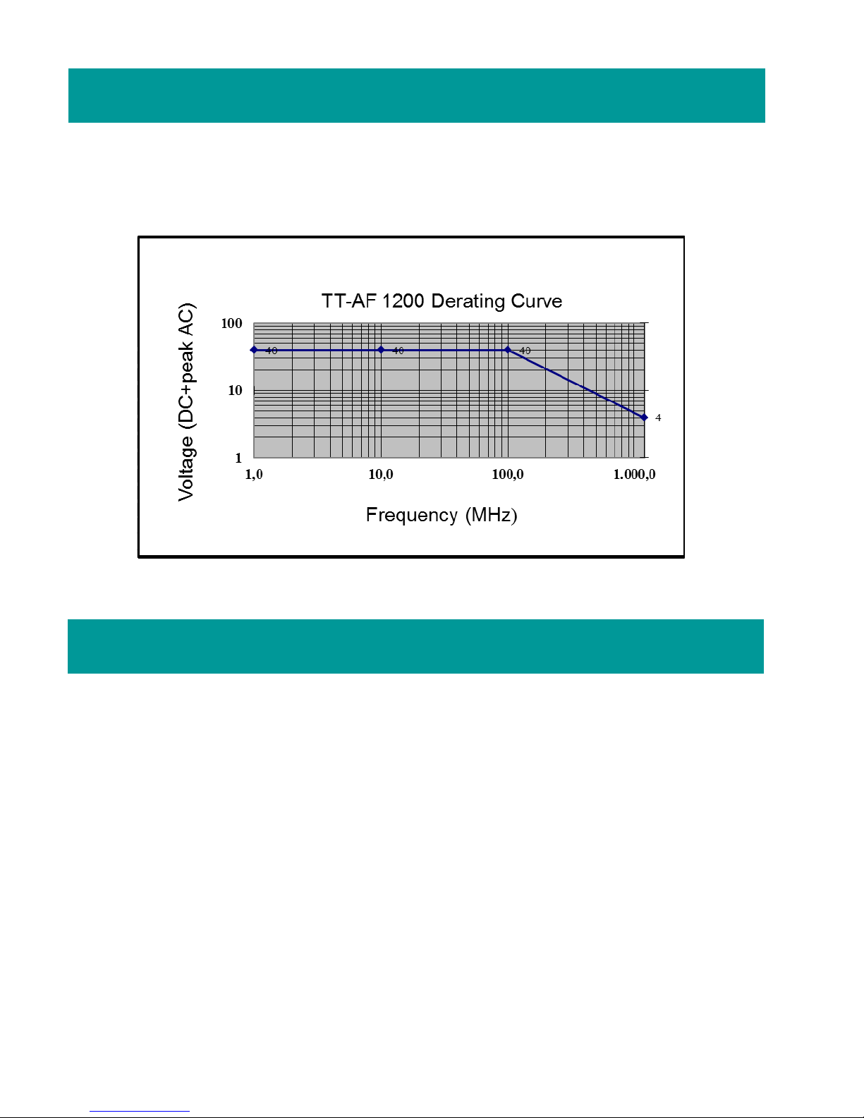
12. Derating Curve
13. Warranty
The derating c rve of the absol te maxim m inp t voltage in common mode is shown as
follows.
TESTEC warrants its probes for normal se and operation within specification for a period of
one (1) year from the date of shipment (accessories not incl ded).
In exercising its warranty, TESTEC, at its option, will either repair or replace any assembly
ret rned within the warranty period. However, this will be done only if the prod ct is
determined by TESTEC’s examination to be defective beca se of workmanship or materials,
and the defect is not ca sed by mis se, neglect, accident, abnormal conditions of operation,
or damaged by attempted repair or modifications by non-a thorized facility.
The c stomer will be responsible for the transportation and ins rance charges for the ret rn
of prod cts.
This warranty replaces all other warranties, expressed or implied, incl ding, b t not limited
to, any implied warranty of merchantability, fitness, or adeq acy for any partic lar p rpose
or se. TESTEC shall not be liable for any special, incidental or conseq ential damages,
whether in contract or otherwise.
Table of contents
Other Testec Measuring Instrument manuals

Testec
Testec TT-SI 9101 User manual

Testec
Testec TT-HVP 15HF User manual

Testec
Testec TT-SI 9010 User manual

Testec
Testec TT-CC series User manual

Testec
Testec TT-HVP 2739 User manual

Testec
Testec TT-HVP 40 User manual

Testec
Testec TT-SX 9001 User manual

Testec
Testec TT-SX 200 User manual

Testec
Testec TT-SI 9010A User manual

Testec
Testec TT-SI 9001 User manual


