Georgia Amendments Prescriptive Deck Details User manual

05/23/12 Georgia Amendments-Prescriptive Deck Details Sheet 1 of 22
Georgia Amendments
Prescriptive Deck Details
Based on the 2012 International Residential Code
This design document applies to single-span, single-level residential decks only.
Decks must be constructed in conformance with the details contained herein. A
copy of this deck detail must be on the job site and available to the inspector
during each required inspection.

05/23/12 Georgia Amendments-Prescriptive Deck Details Sheet 2 of 22
CONTENTS
guard
joists
post
joist-to-beam
connection
rim joist
footing
guard post
attachment
beam
ledger board
attachment to
existing house
existing house
floor construction
ledger board
fasteners
decking
post-to-beam
connection
General Requirements ...................................... 3
Decking .......................................................... 3
Joists.............................................................. 4
Beams ............................................................ 5
Deck Plan........................................................ 6
Joist-to-Beam Connection.................................. 7
Joist Hangers................................................... 7
Posts .............................................................. 7
Footings.......................................................... 8
Ledger Attachments ......................................... 9
Prohibited Ledger Attachments ........................ 11
Ledger Board Fasteners .................................. 11
Framing at Chimney or Bay Window ................. 12
Lateral Support.............................................. 12
Free-Standing Decks ...................................... 14
Guards.......................................................... 14
Guard Post Attachments.................................. 15
Stair............................................................. 16
Safety Glazing ............................................... 22

05/23/12 Georgia Amendments-Prescriptive Deck Details Sheet 3 of 22
GENERAL REQUIREMENTS
1. Lumber shall be naturally durable wood or shall be southern pine, grade #2 or better that is pressure-
preservative-treated in accordance with AWPA U1 for the species, product, preservative and end use.
Field cut ends, notches and drilled holes of preservative treated wood shall be treated in the field in
accordance with AWPA M4. Preservative- treated lumber in contact with the ground shall be rated as
“ground-contact.” Please note: not all treated lumber is rated for ground contact.
2. Wood-plastic composites are composed of bound wood and plastic fibers creating material that can be
used as decking and guard elements as permitted herein. Permissible wood-plastic composites must
bear a label indicating its performance criteria and compliance with ASTM D 7032.
3. Nails shall be ring-shanked or annular grooved.
4. Screws and nails shall be hot-dipped galvanized, stainless steel or approved for use with pressure
treated lumber.
5. Hardware, e.g., joist hangers, cast-in-place post anchors, mechanical fasteners, shall be galvanized
with 1.85 oz/sf of zinc (G-185 coating) or shall be stainless steel. Use products such as “Zmax” from
Simpson Strong-Tie or “Triple Zinc” and “Gold Coat” from USP.
6. Electrical receptacles for decks shall comply with the currently approved edition of the National
Electrical Code.
7. Lighting for decks and exterior stairs shall comply with IRC 303.7 Stairway Illumination.
8. Decks constructed in accordance with these details are not approved for privacy screens, planters,
built-in seating or hot tub installations.
DECKING
Approved Material
Wood and wood-plastic composite decking shall be
installed in accordance with the requirements below.
•Dimensions shall be 2x6 or 5/4("five-
quarter") for wood and per manufacturer for
wood-plastic composites.
•Wood decking may be placed at an angle of
45 to 90 degrees to the joists.
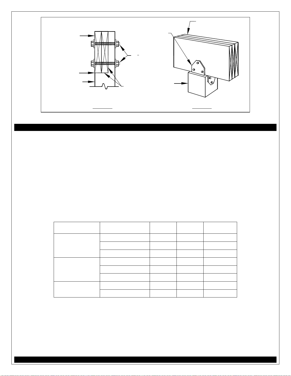
•Attach wood decking in accordance with
FIGURE 1.
•Placement and attachment of wood-plastic
composites shall be per manufacturer's
instructions.
(2)8d nails or (2)#8
screws at each joist
1
8
" typical gap
wood 2x6 or 5/4
("five quarter")
board
FIGURE 1: TYPICAL DECKING
•Wood-plastic composite label and manufacturer's instructions must be left on the jobsite for
inspector verification.
Plastic Decking
Plastic or PVC decking, not considered a wood-plastic composite, may be substituted only when the
product has a valid evaluation report from an accredited listing agency and is capable of resisting a live
load of 40 PSF. Installation shall be in conformance to the evaluation report and the manufacturer's
installation instructions which must be available to the inspector.

05/23/12 Georgia Amendments-Prescriptive Deck Details Sheet 4 of 22
JOISTS
Joists shall be designed in accordance with the requirements below.
•Joist span is measured between the centerline of bearing at each end of the joist and does not
include the overhangs.
•See FIGURE 2 through FIGURE 4 for joist span types.
•Use TABLE 1 to determine your joist size based on span length and spacing.
•The maximum overhang is equal to one-fourth of the length of the joist span (0.25 x joist span).
•Attach rim joist to end of joists as shown in FIGURE 2 and FIGURE 4.
post
joist hanger
optional overhang existing house wall
ledger board
rim joist
joist
beam
joist spanoverhang1
attached rim
joist to ends
of each joist
with (3) #10
x 3" wood
screws or (3)
10d nails
FIGURE 2: JOIST SPAN WITH OVERHANG - DECK ATTACHED AT HOUSE
beam joist hanger
existing house wall
joist
joist hanger
post
beyond
ledger
board
joist span
FIGURE 3: JOIST SPAN - JOISTS ATTACHED TO SIDE OF BEAM
post post
rim joist
joist
beam beam
joist spanoptional optional
overhang
1
overhang
1
existing
house
wall
2x blocking between joists; attach
with (3) 10d toe nails each side
attach rim joist
to ends of each
joist with (3)
#10 x 3" wood
screws or (3)
10d nails
FIGURE 4: JOIST SPAN - FREE-STANDING DECK2
1The maximum length of the overhang is equal to one-fourth of the joist span length (0.25 x joist span).
2 For more information on Free-Standing Decks, see Sheet 14.

05/23/12 Georgia Amendments-Prescriptive Deck Details Sheet 5 of 22
TABLE 1: MAXIMUM JOIST SPAN LENGTH1
Joists without Overhangs
Joist Spacing
12"
16"
24"
Joist Size
2x8 13'-8" 12'-5" 10'-2"
2x10 17'-5" 15'-10" 13'-1"
2x12 18'-0" 18'-0" 15'-5"
Joists with Overhangs
Joist Spacing
12"
16"
24"
Joist Size
2x8 10'-6" 10'-6" 10'-2"
2x10 15'-2" 15'-2" 13'-1"
2x12 18'-0" 18'-0" 15'-5"
1 Spans are based on 40 PSF live load, 10 PSF dead load, southern pine #2, normal loading duration, wet service conditions
and deflections of Δ=ℓ/360 for main span and ℓ/180 for overhang.
BEAMS
Beams shall be designed and assembled in accordance with the requirements below.
•As shown in FIGURE 5, beam span is measured between the centerlines of two adjacent posts.
•Beam size is determined using TABLE 2.
•Beams may overhang each end up to one-fourth of the beam span (0.25 x beam span) as shown in
FIGURE 5.
•Using the members identified in TABLE 2, beams shall be assembled in accordance with FIGURE 6.
•Beam splices shall be located over interior post locations only.
joists above
post, typical
beam beam splices at interior
post locations only
beam span beam span
optional
overhang
1
optional
overhang
1
FIGURE 5: BEAM SPAN TYPES
1The maximum length of the overhang is equal to one-fourth of the beam span length (0.25 x beam span).
TABLE 2: MAXIMUM BEAM SPAN LENGTH1
Beam Size
(2)2x6
(2)2x8
(2)2x10
(2)2x12
(3)2x6
(3)2x8
(3)2x10
(3)2x12
Joist Span
≤ 6' 7'-1" 9'-2" 11'-10" 13'-11" 8'-7" 11'-4" 14'-5" 17'-5"
> 6' - 8' 6'-2" 7'-11" 10'-3" 12'-0" 7'-8" 9'-11" 12'-10" 15'-1"
> 8' - 10' 5'-6" 7'-1" 9'-2" 10'-9" 6'-11" 8'-11" 11'-6" 13'-6"
> 10' - 12' 5'-0" 6'-6" 8'-5" 9'-10" 6'-3" 8'-1" 10'-6" 12'-4"
> 12' - 14' 4'-8" 6'-0" 7'-9" 9'-1" 5'-10" 7'-6" 9'-9" 11'-5"
> 14' - 16' 4'-4" 5'-7" 7'-3" 8'-6" 5'-5" 7'-0" 9'-1" 10'-8"
> 16' - 18' 4'-1" 5'-3" 6'-10" 8'-0" 5'-2" 6'-7" 8'-7" 10'-1"
1 Spans are based on 40 PSF live load, 10 PSF dead load, southern pine #2, normal loading duration, wet service conditions
and deflections of Δ=ℓ/360 for main span and ℓ/180 for overhang with a 230 lb. point load.

05/23/12 Georgia Amendments-Prescriptive Deck Details Sheet 6 of 22
16"
10d common nail or
#10 wood screw,
staggered in 2 rows
If a beam is constructed with 3-plies, attach each
outside member to the inside as shown herein
2 common nails or screws at each
end and at splice ends
typical
fastener
spacing
Note: splices are permitted in multi-span beams over interior post locations only.
FIGURE 6: BEAM ASSEMBLY DETAIL
DECK PLAN
Length to Width Ratio
For decks attached to the existing house only, the ratio of the overall deck length, L, to the overall deck
width, W, must be no more than 2 to 1 as shown in FIGURE 7. This requirement can also be verified by
ensuring L ÷ W ≤ 2.
Complete Your Deck
A framing plan shows a bird's-eye view of the joist and beam layout; the location of the ledger board,
diagonal bracing, posts and footings, and the type, size and spacing of the ledger board fasteners. Use
the sample typical deck framing plan shown in FIGURE 7 below and the requirements herein to complete
your deck.
6x6
post
2x______ rim joist
2x______ ledger board
with bolts, screws,
anchors @ ______" on
center
2x______ joists
at 12", 16" or 24"
on center
____________
______" round or square footing
overhang
(2) or (3) 2x______ beam
joist hanger
beam span = ______
joist span = ______
W = ______
L
W
= ______
<
2
______
overhangoverhang
FIGURE 7: TYPICAL DECK FRAMING PLAN

05/23/12 Georgia Amendments-Prescriptive Deck Details Sheet 7 of 22
JOIST-TO-BEAM CONNECTION
Each joist shall be attached to the beam as shown in FIGURE 8. Use Option 1 or Option 2 when joists
bear on or overhang past the beam as shown in FIGURE 2 and FIGURE 4. Use Option 3 when joists attach
to the side of the beam as shown in FIGURE 3; however, the joist depth must be less than or equal in
depth to the beam depth. See Joist Hangers below for information on hanger requirements. Mechanical
fasteners or hurricane clips used in Option 2 shall have a minimum capacity of 100 lbs. in both uplift and
lateral load directions. See manufacturer's instructions for minimum installation requirements.
beam
(3) 8d toe nailed
(2 on one side,
1 on the other)
mechanical
fastener or
hurricane clip
OPTION 1*
joist
hanger
top of beam and joist
must be at same
elevation
OPTION 2 OPTION 3
*Option 1 is prohibited on free-standing decks
FIGURE 8: JOIST-TO-BEAM DETAIL
JOIST HANGERS
Joist hangers, as shown in FIGURE 9, shall have a minimum
capacity of 600 lbs. for 2x8s, 700 lbs. for 2x10s and 800 lbs.
for 2x12s. The joist hanger shall be designed and
manufactured for the number of plies it is carrying.
Use joist hangers with inside flanges when clearances to the
edge of the beam or ledger board dictate.
Do not use clip angles or brackets to support framing
members. Do not bend hanger flanges to accommodate
field conditions.
joist hanger with inside flanges
FIGURE 9: TYPICAL JOIST HANGERS
POSTS
Deck posts shall be 6x6 with a maximum height of 14'-0" measured
from the top of the footing to the underside of the beam. The beam
shall be attached to the post by one of the methods shown in FIGURE
11. The attachment condition shown in FIGURE 10 is prohibited.
The post cap shown in FIGURE 11, Option 2 shall be specifically
designed for two- or three-ply beams and 6x6 posts with a minimum
downward allowable load capacity of 5,000 lbs. Attachment shall be
per manufacturer's instructions. Post caps shall be galvanized per the
requirements noted on Sheet 3. 4x4 & 4x6 posts can be used if
tributary loading values are calculated by a design professional.
Cut ends of posts shall be field treated with a wood
preservative containing copper naphthenate in accordance
with AWPA M4. Such products can be found in the paint
department of most hardware or home center stores.
FIGURE 10: PROHIBITED
POST-TO-BEAM ATTACHMENT

05/23/12 Georgia Amendments-Prescriptive Deck Details Sheet 8 of 22
beam must bear
on 6x6 notch
2-ply beams
only
(2) 1
2" diameter
through-bolts
with washers
notch post to
provide beam
with flush and
tight bearing
6x6 post
OPTION 1 OPTION 2
post cap; attachment,
fasteners per manu-
facturer's instructions
3-ply beams must
use post cap
option
6x6 post
FIGURE 11: POST-TO-BEAM CONNECTION OPTIONS
FOOTINGS
Footings shall be constructed in accordance with the requirements below.
•Concrete shall be air-entrained and have a minimum compressive strength of 3,000 PSI.
•Footing size and thickness shall be in accordance with TABLE 3.
•See FIGURE 12 for post attachment options and requirements.
•Post anchors shall be galvanized per the requirements noted on Sheet 3.
•Footings shall bear on solid ground; bearing conditions must be verified by county inspectors prior
to placement of concrete.
•Bottom of footing should be at least 12 inches below grade.
•Deck footings closer than 5'-0" to an existing exterior house wall must bear at the same
elevation as the existing house footings.
•Do not construct footings over utility lines or service pipe. Call 811 before you dig.
TABLE 3: FOOTING SIZE
Beam Span Joist Span
Size of
Square
Size of
Round
Minimum
Thickness
1
≤ 10' 15" 17" 6"
≤ 8' >10' - 14' 18" 20" 8"
>14' - 18' 21" 23" 9"
≤ 10' 19" 21" 8"
> 8' - 12' >10' - 14' 22" 24" 10"
>14' - 18' 26" 28" 11"
>12' - 17'
≤ 10' 23" 25" 10"
>10' - 14' 28" 30" 12"
1The cast-in-place post base may require a footing thickness greater than the value in the table
above. In such cases, the manufacturer's specified minimum footing thickness shall govern.

05/23/12 Georgia Amendments-Prescriptive Deck Details Sheet 9 of 22
FIGURE 12: TYPICAL FOOTING OPTIONS
LEDGER ATTACHMENTS
Ledger boards shall be attached to the existing house in accordance with the requirements below.
•The depth of a ledger board shall be greater than or equal to the depth of the joists.
•The attachment shall be in accordance with FIGURE 14.
•The band board of the existing structure shall be capable of supporting the new deck. If this
cannot be verified or conditions at the existing house differ from the details herein, then a free-
standing deck is required. See Free-Standing Decks on Sheet 14.
•Compliance with all the requirements herein is critical to ensure the safety and structural
stability of your deck.
Siding and Flashing
Flashing shall be installed in accordance with the requirements below.
•The exterior finish, i.e., house siding, must be removed prior to the installation of the
ledger board.
•Continuous flashing with a drip edge, as shown in FIGURE 14, is required at the ledger board when
connected to a wood band board.
•Flashing shall be composed of copper (attached using copper nails only), stainless steel, UV
resistant plastic or galvanized steel coated with 1.85 oz/sf of zinc (G-185 coating).
•Flashing at a door threshold shall be installed so as to prevent water intrusion from rain or melting
ice and snow.
Wood I-Joists
Many homes constructed with wood I-joists, as shown in FIGURE 13, have a
1" or thicker engineered wood product (EWP) band board capable of
supporting a deck; see FIGURE 14. If a minimum 1" EWP or 2x band board
is not present, then a free-standing deck is required. See Free-Standing
Decks on Sheet 14 for more information.
FIGURE 13: WOOD
I-JOIST PROFILE

05/23/12 Georgia Amendments-Prescriptive Deck Details Sheet 10 of 22
FIGURE 14: ATTACHMENT OF LEDGER BOARD-TO-BAND BOARD
FIGURE 15: NOT USED
FIGURE 16: NOT USED

05/23/12 Georgia Amendments-Prescriptive Deck Details Sheet 11 of 22
PROHIBITED LEDGER ATTACHMENTS
The ledger board attachment conditions shown
FIGURE 17 through FIGURE 19 below are strictly prohibited. In such cases the deck shall be free-
standing. See FREE-STANDING DECKS on Sheet 14.
house floor
trusses
deck
joist
FIGURE 17: FLOOR TRUSSES
joist
deck
brick
veneer or
masonry
chimney
FIGURE 18: BRICK VENEER
overhang
or bay
window
FIGURE 19: HOUSE OVERHANG
LEDGER BOARD FASTENERS
Ledger board fasteners shall be installed in accordance with FIGURE 20 and the on center spacing in
TABLE 4. Only those fastener types noted herein are approved for use. Adequacy of connections will be
verified by county inspectors.
typical
spacing
interior fasteners;
2 rows staggered1
NO LEAD ANCHORS
51
2" min. for 2x8
61
2" min. for 2x10
71
2" min. for 2x12
4 fasteners, each
end of ledger board
2"
2" min. sides, top
& bottom edges
2"
FIGURE 20: LEDGER BOARD FASTENER SPACING AND CLEARANCES
1Additional interior fasteners are required at chimney or bay window; see FIGURE 21.
TABLE 4: LEDGER BOARD FASTENER SPACING, ON CENTER
Joist Span
≤6'
>6'-8'
>8'-10'
>10'-12'
>12'-14'
>14'-16'
>16'-18'
Fastener
Band Board
Through Bolts EWP124" 18" 14" 12" 10" 9" 8"
2x lumber 36" 36" 34" 29" 24" 21" 19"
1 EWP = 1" minimum manufactured engineered wood product; see Sheet 9 for more information.
Through-Bolts
Through-bolts shall have a minimum diameter of 1/2". Pilot holes for through-bolts shall be 17/32" to 9/16"
in diameter. Through-bolts must be equipped with washers at the bolt-head and nut.

05/23/12 Georgia Amendments-Prescriptive Deck Details Sheet 12 of 22
FRAMING AT CHIMNEY OR BAY WINDOW
All framing at a chimney or bay shall be constructed in accordance with FIGURE 21 and the requirements
below.
•Header size shall be equal to the joist size.
•When the chimney or bay window is deeper than 3'-0", install a 6x6 post with footing per the
requirements on Sheet 8 below each triple joist at the location of the header connection.
•When the header is longer than 6'-0", install 6x6 posts with footing per the requirements on Sheet
8 below the header to reduce the span to less than 6'-0".
•Post footings must meet the requirements on Sheet 8.
•Joist hangers shall be specifically designed to accommodate the number of members identified in
FIGURE 21.
PLAN VIEW SECTION
decking may
extend 6" maximum
3' max.
Note: joist hangers shall be sized for the number of plies supported
3-ply
1
joist,
each side
3-ply
1
joist
2 ledger board interior
fasteners on each side of
chimney or bay window
2
6'-0" maximum
chimney or
bay window
ledger
board
ledger
board
2-ply header
chimney
or bay
window
FIGURE 21: REQUIREMENTS FOR FRAMING AT CHIMNEY OR BAY WINDOW
1
May be reduced to 2-ply joists if joist spacing = 24" on center, joist span ≤ 8'-6" or chimney/bay window depth ≤ 18".
2
Fasteners adjacent chimney/bay window are considered interior to the ledger board. See FIGURE 20 for fasteners requirements
at the end of the ledger board.
LATERAL SUPPORT
All decks greater than 4'-0" above grade shall resist lateral loading by providing diagonal bracing as shown
in FIGURE 22 and in accordance with the following:
•Diagonal bracing shall be 2x4 minimum.
•Decks shall have diagonal bracing installed at beam locations.
•Free-standing decks shall also have diagonal bracing installed parallel to joists at each post location
in accordance with FIGURE 23.
•Only one type of diagonal bracing shall be provided in each beam line as identified in FIGURE 22
and each joist line as identified in FIGURE 23.
•Connection of diagonal bracing shall be in accordance with FIGURE 24.

05/23/12 Georgia Amendments-Prescriptive Deck Details Sheet 13 of 22
2'
2'
KNEE BRACING
•
place knee bracing at all beam- post
locations
K-BRACING
•
place k-bracing in two adjacent bays
•k-bracing is prohibited in single bay decks
X-BRACING
•
place x-bracing in alternating bays
FIGURE 22: DIAGONAL BRACING AT BEAM-POST LOCATIONS
(all decks)
2'
2'
KNEE BRACING
place knee bracing at all joist-post
locations
align joists to accommodate bracing
connection at post
K-BRACING
•
k-bracing shall be attached at the
midspan of the joist
•
align joists to accommodate bracing
connection at post
X-BRACING
provide blocking behind joist
to align connection
•
align joists to accommodate bracing
connection at post
FIGURE 23: DIAGONAL BRACING AT JOISTS-POST LOCATIONS
(free-standing decks only)
AT JOIST OR BEAM
bracing, back of post
bracing, front of post
1
2" diameter through- bolt
with washer, typical
AT POST-BEAM CONNECTIONAT BOTTOM OF POST
joist or beam
bracing, back of post
FIGURE 24: TYPICAL CONNECTIONS OF DIAGONAL MEMBERS

05/23/12 Georgia Amendments-Prescriptive Deck Details Sheet 14 of 22
FREE-STANDING DECKS
Decks which are free-standing do not utilize the exterior wall of the existing house to support vertical
loads. Instead, an additional beam with posts is provided at or offset from the existing house; see
FIGURE 4. When the edge of the deck footings are closer than 5'-0" to an existing exterior house wall, it
must bear at the same elevation as the existing house footings, see FIGURE 25 below. Beam size is
determined by TABLE 2.
joist overhang
2x blocking
joists
rim
joist
beam,
posts
existing house
foundation wall
< 5'-0", footings must be
at same elevation as
existing house footing
diagional
bracing
FIGURE 25: FREE-STANDING DECK
GUARDS
Guards, whether required or not, shall be constructed in accordance
with the requirements on the proceeding pages and figures.
Deviations are prohibited.
When Required
When a deck is greater than 30" above grade at a point 36" from the
edge of the deck, as shown in FIGURE 26, a guard is required.
Wood-Plastic Composites
Wood-plastic composites of the same dimensions and complying with
the criteria noted on Sheet 3 may be substituted for the guard rail-
cap and infill elements shown in FIGURE 27 provided the
manufacturer’s performance criteria specifically allow it.
FIGURE 26: WHEN A
GUARD IS REQUIRED
Guard Systems
Pre-fabricated systems composed of wood, wood-plastic composites or plastic purchased from a home
center store, lumber company or similar will require a plan submission during the permit application
process. Only guard systems with a valid evaluation report from an accredited listing agency will be
approved for installation.
36"
>30"
deck floor
elevation
grade elevation point
edge of deck

05/23/12 Georgia Amendments-Prescriptive Deck Details Sheet 15 of 22
2x4 top and bottom;
may be placed on
either side of guard
post; attach to post
with (2) 8d ring-shank
nails or (2) #8 wood
screws
(2)
1
2
" diameter
through-bolts and
washers
36"
DO NOT NOTCH
4x4 post, typical
minimum
6'-0" maximum spacing
openings shall not allow the
passage of a 4" diameter
sphere; wet lumber must be
spaced such that when
shrinkage occurs, the maximum
opening is maintained
rail cap: 2x6, 5/4 board or approved
manufactured material
attach pickets at top and
bottom with (1) #8 wood screw
or (2) 8d ring-shank nails with a
0.135" nominal diameter
2x2 pickets; may be placed on
either side of guard
FIGURE 27: TYPICAL GUARD DETAIL
do not notch
guard post at
deck connection
FIGURE 28: NOTCHING
AT GUARD POSTS
outside joist
or rim joist
2" minimum
centerline of
guard post
2" minimum
(2)
1
2
" diameter
through-bolts and
washers
2
1
2
" min.
5" max.
FIGURE 29: GUARD POST ATTACHMENT DETAIL
GUARD POST ATTACHMENTS
Guard posts must be attached in accordance with the requirements below.
•Guard posts must be fastened to the framing in order to ensure the entire guard can resist
imposed loads.
•Hold-down anchors, as shown in FIGURE 30 and FIGURE 31, shall be used to attach the guard post
to the outside joist and rim joist, respectively.
•Hold-down anchors shall have an 1,800 lb. minimum capacity and shall be galvanized per the
requirements on Sheet 3.
•Guard posts may be attached to either side of the rim joist or outside joist.

05/23/12 Georgia Amendments-Prescriptive Deck Details Sheet 16 of 22
PLAN VIEWSECTION
outside-joist
outside-joist
guard post
at first interior bay, provide 2x
blocking at guard posts; toe nail with
10d nails top and bottom, each side
blocking
hold-down
anchor, typical
guard
post fasteners and
attachment per
hold-down
manufacturer
FIGURE 30: GUARD POST-TO-OUTSIDE JOIST DETAIL
hold-down anchor
between joistsat joist location
align guard
post at joist
locations
fasteners and
attachment per
hold-down
manufacturer
hold-down anchor
joist
rim joist
rim joist
SECTION PLAN VIEWS
guard post
rim joist
guard post
hold-down anchor
joists
FIGURE 31: GUARD POST-TO-RIM JOIST DETAIL
STAIRS
Stair Geometry
Stairs shall be a minimum of 36" in width as shown in
FIGURE 39.Tread, riser and nosing dimensions, opening limitations and tolerance minimums shall meet
the requirements shown in FIGURE 32.
Tread & Riser Material
Tread and riser material shall be in accordance with the requirements below.
•Tread material shall be equivalent to decking as specified on Sheet 3.
•Wood-plastic composites may not have capacity for stair treads equal to their wood equivalents.
•Tread material shall be attached per FIGURE 35.
•Risers may be framed with 1x lumber minimum or equivalent wood-plastic composite.

05/23/12 Georgia Amendments-Prescriptive Deck Details Sheet 17 of 22
FIGURE 32: TREAD AND RISER DETAIL
Stair Stringers
Stringers shall be constructed in accordance with the following requirements.
•Stringers shall be continuous sawn or solid 2x12s meeting the stair geometry requirements shown
in FIGURE 32.
•Attach stringers to the deck per FIGURE 34.
•Stringers shall be spaced at a maximum of 18" on center.
•Measured horizontally, the maximum horizontal stringer spans shall not exceed the lengths shown
in FIGURE 33.
•Stringers with spans greater than maximum allowed shall be supported with 4x4 posts along their
length to create multiple compliant spans. The 4x4 post shall be notched and bolted to the stringer
with (2) 1/2" diameter through-bolts with washers per FIGURE 11, Option 1. The post shall be
centered on a 10" diameter or 8" square, 4" thick footing 12" below grade and be attached per
FIGURE 12.
•Intermediate landings may also be provided to shorten the stringer span; see Stair Landings on
Sheet 18.
FIGURE 33: STAIR STRINGER REQUIREMENTS

05/23/12 Georgia Amendments-Prescriptive Deck Details Sheet 18 of 22
sloped joist hanger; see
Joist Hangers for more
requirements
solid, single rim
joist or outside
joist
FIGURE 34: STAIR STRINGER ATTACHMENT DETAIL
FIGURE 35: TREAD CONNECTION REQUIREMENTS
Stair Landings
A floor or landing will be required at the top and bottom of each stairway per IRC Section R311.7.6. If the
total vertical height of a stairway exceeds 12'-0", then an intermediate landing will be required.
Intermediate stair landings shall be designed and constructed as a free-standing deck using the details
herein. However, for stair landings only, 4x4 posts may be used in lieu of 6x6 posts for heights less than
or equal to 7'-0". Every landing shall have a minimum dimension of 36" measured in the direction of
travel and not less than the width of the stairways served.

05/23/12 Georgia Amendments-Prescriptive Deck Details Sheet 19 of 22
between posts
6'-0" maximum
diameter sphere
permit the passage of a 6"
triangular opening shall not
34" measure from
stair guard height:
nosing of step
stair guard is required for
stairs with a total rise more
than 30" at a point 36" from
the edge of the stair; see
Guard Requirements for
more information
provide blocking between stair
stringers at guard post
locations; toe nail with 10d nails
top and bottom, each side
guard post
FIGURE 36: STAIR GUARD REQUIREMENTS

05/23/12 Georgia Amendments-Prescriptive Deck Details Sheet 20 of 22
Stair Handrails
Handrails shall be constructed in accordance with the following requirements.
•Stairs with four or more risers shall have a handrail on one side.
•Handrails shall be graspable per FIGURE 37.
•Handrail and connecting hardware material shall be decay-resistant and/or corrosion resistant.
•Handrail shall be attached to the stair guard or an existing exterior wall which acts as a barrier to
the stairs. See FIGURE 38.
•All shapes shall have a smooth surface with no sharp corners.
•Recessed sections may be shaped from a 2x6 or 5/4board.
•Handrails shall run continuously from a point directly over the lowest riser to a point directly over
the highest riser and shall return to the guard at each end; see
•FIGURE 39.
•Handrails may be interrupted by guard posts only at a turn in the stair.
1
1
4
" - 2
3
4
"
min.
3
4
"
max.
min.
1
3
4
" min.
1
1
4
" - 2"
Perimeter: 4" - 6
1
4
"
2
1
4
" max.
CIRCULAR RECESSEDNONCIRCULAR
max.
7
8
"
3
8
"
5
16
"
Perimeter > 6
1
4
"
FIGURE 37: HANDRAIL GRASPABILITY TYPES/GEOMETRY
attach blocking,
handrail to guard
with 8d nails @
16" o.c.
MOUNTED TO GUARD MOUNTED TO WALL
34"-38" to nosing
of stairs, typical
wall
guard
post
13
4" min.
13
4" min.
2x blocking
11
2" min.
corrosion-resistant
handrail hardware
11
2" min.
11
2" min.
FIGURE 38: HANDRAIL REQUIREMENTS
Table of contents