manuals.online logo
Brands
  1. Home
  2. •
  3. Brands
  4. •
  5. Geosense
  6. •
  7. Gateway
  8. •
  9. Geosense WI-SOS 480 User manual

Geosense WI-SOS 480 User manual

4
5
4GruggedGateway-Edge
loadsensing
BY WORLDSENS NG Industrial MonitoringSolution
Barcelon
Viriat 47, Edicio Numancia 1, 10th oor
08014 Barcelona, Spai
(+34) 93 418 05 85
www.worldsensing.com/suppor
connect@worldsensing.com Los AngelesLondon Singapore
QUICK START GUIDE
Gateway components
Gateway Information Sheet
1
2
3
6
7
8
10
9
11
Gateway Information Sheet Gateway Login elds
Remote access user
Default remote and local access
password
Username
Password
Gateway Information Sheet
(
SAMP
L
E

Serial
N
um
b
er
:
12345678

Gateway ID
:
123

Remote access url
:
https
://
loadsensing
.
wocs
.
com
/
123

L
ocal access url
:
https
://
169
.
254
.
0

Remote access user
:
admi

Default remote and local access password
:
sample passwor

Default networ
k
ID
:
123

Default networ
k
k
ey
:
sample passwor

IMEI
:
00000000
SAMP
L
E
ONLY
This gateway is compati
b
le with CMT Edge and all
L
oadsensing edge de
v
ices
.
It features the following parts


1 M25 ca
b
le gland

2 Ca
b
le gland

3 Seal

4 Plastic support

5 E
x
ternal nut

6 SIM Card slot

7 PoE in
j
ector

8
O
ptional
v
ertical omni
-
directional antenna

9 Antenna
N
adapter

10 Power o
v
er Ethernet
(
PoE
)
adapter

11 US
B-
Ethernet adapter

loadsensing
BY WORLDSENSING Industria Monitoring So ution
Barcelon
Viriat 47, Edicio Numancia 1, 10th oor
08014 Barcelona, Spai
(+34) 93 418 05 85
www.worldsensing.com/suppor
connect@worldsensing.com Los AngelesLondon Singapore
Step 1 - Set up the power suppy
Step 3 - Power up the gateway
Step 2 - Seect the Internet interface
Se ect the appropriate Ethernet cab e to connect the gateway to the PoE and add
RJ-45 connectors on both sides. We recommend STP or SSTP which are designed to
be insta ed outdoors if required. The cab es shou d 6.6-8.8mm in diameter and at
most 100 meters in ength.

Insta the cab e g and as shown on the photo and tighten it on the gateway side.

Connect the ethernet cab e to the RJ-45 Port of the PoE injector abe ed “DATA &
POWER OUT”
Etherne
Connect one end of the Ethernet cab e to the network and the
other end to the RJ-45 port of the Poe Injector abe ed “DATA IN”
P ug the PoE injector to the mains
(
AC
)
.

Check the
L
ED disp ay at the bottom
G
reen
L
ED steady
:
G
ateway is powered
Red
L
ED b inking
:
G
ateway is booting
Red
L
ED o
:
G
ateway is a ready booted.
The gateway can be connected to the Internet through the fo owing
:

Ce u ar
(
SIM Card up to 4
G)
Unscrew the atera co
v
er with a M25 wrench
Insert the SIM Card
C ose and tighten the co
v
er again.
loadsensing
BY WORLDSENSING Industria Monitoring So ution
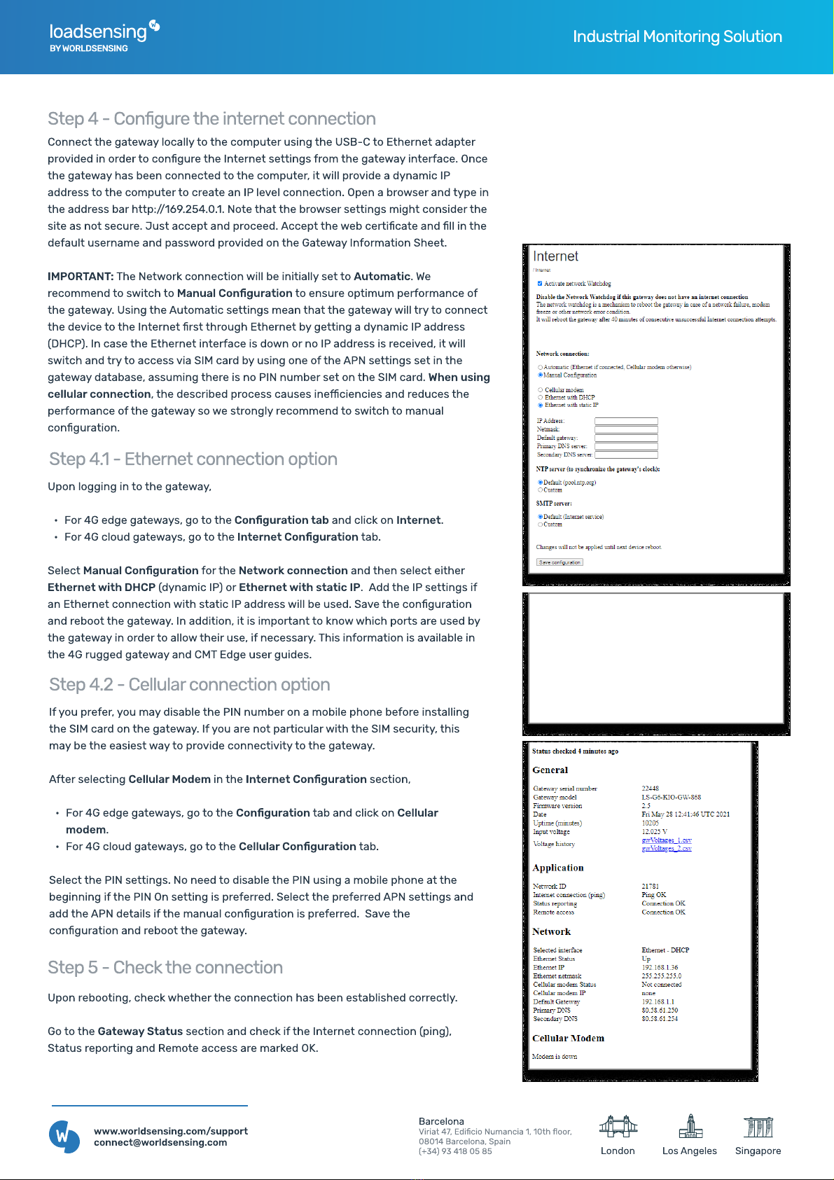
Step 4.1 - Ethernet connection option
Upon ogging in to the gateway
 For 4G edge gateways, go to the Conguration tab and c ick on Internet.
 For 4G c oud gateways, go to the Internet Conguration tab.

Se ect Manual Conguration for the Network connection and then se ect either
Ethernet with DHCP (dynamic IP) or Ethernet with static IP. Add the IP settings if
an Ethernet connection with static IP address wi be used.Save the conguration
and reboot the gateway. In addition, it is important to know which ports are used by
the gateway in order to a ow their use, if necessary. This information is avai ab e in
the 4G rugged gateway and CMT Edge user guides

Step 4.2 - Ce uar connection option
If you prefer, you may disab e the PIN number on a mobi e phone before insta ing
the SIM card on the gateway. If you are not particu ar with the SIM security, this
may be the easiest way to provide connectivity to the gateway
After se ecting Cellular Modem in the Internet Conguration section,
 For 4G edge gateways, go to the Conguration tab and c ick on Cellular
modem.
 For 4G c oud gateways, go to the Cellular Conguration tab.
Se ect the PIN settings. No need to disab e the PIN using a mobi e phone at the
beginning if the PIN On setting is preferred.Se ect the preferred APN settings and
add the APN detai s if the manua conguration is preferred. Save the
conguration and reboot the gateway
Step 4 - Congure the internet connection
Connect the gateway oca y to the computer using the US
B
-C to Ethernet adapter
provided in order to congure the Internet settings from the gateway interface. Once
the gateway has been connected to the computer, it wi provide a dynamic IP
address to the computer to create an IP eve connection. Open a browser and type in
the address bar http
://
1
69
.2
5
4.
0
.1. Note that the browser settings might consider the
site as not secure.
J
ust accept and proceed.Accept the web certicate and  in the
defau t username and password provided on the Gateway Information Sheet
IMP
ORTA
N
T:
The Network connection wi be initia y set to
A
utomatic.
W
e
recommend to switch to Manual Conguration to ensure optimum performance of
the gateway. Using the Automatic settings mean that the gateway wi try to connect
the device to the Internet rst through Ethernet by getting a dynamic IP address
(
DH
CP). In case the Ethernet interface is down or no IP address is received, it wi
switch and try to access via SIM card by using one of the APN settings set in the
gateway database, assuming there is no PIN number set on the SIM card.
W
hen using
cellular connection, the described process causes ine

ciencies and reduces the
performance of the gateway so we strong y recommend to switch to manua
conguration.
B
a
rc
elon

V
i
r
ia
t 47, E
di
c
io
Num
an
c
ia
1, 10th 
oo
r
08014 B
a
rc
elona
, Sp
ai

(+34) 93 418 05 85
www
.
worldsensing
.
com
/
su
pp
or

connect
@
worldsensing
.
com
L
os
A
ngeles
L
ondon
S
inga
p
o
r
e
Step
5
- Check the connection
Upon rebooting, check whether the connection has been estab ished correct y.
Go to the
G
atewa
y
S
tatus section and check if the Internet connection (ping),
Status reporting and
R
emote access are marked O
K
.
loadsensing
BY WORLDSENSING Industria Monitoring So ution
Barcelon
Viriat 47, Edicio Numancia 1, 10th oor
08014 Barcelona, Spai
(+34) 93 418 05 85
www.worldsensing.com/suppor
connect@worldsensing.com Los AngelesLondon Singapore
GENERAL DISCLAIMER:
Specications are subject to change without notice and shou d not be construed as a commitment by Wor dsensing. Wor dsensing assumes no responsibi ity for any
errors that may appear in this document. In no event sha Wor dsensing be iab e for incidenta or consequentia damages arising from the use of this document or
the systems described in this document.
Step 6 - Insta the gateway
WALL FIXING: 
Use four 6mm screws to x the
gateway using the ho es at the
4 corners of the bracket.
POLE FIXING:
Use two hose c amps to x
the gateway to a po e. 
Two openings are reserved
for horizonta or vertica po e
xing.
The width of the hose
c amps shou d not exceed
14mm.
To mount the gateway
,
push it
down to x it to the 4 meta ic
bo ts on the temp ate and
screw the mounting bo t at the
bottom to ock it in p ace.
To unmount the gateway
,
unscrew the mounting bo t and
move the gateway up. The
temp ate wi remain insta ed
and ready for a new gateway to
be mounted.
Fina y
,
insta the earthing in
the earthing screw to protect
the gateway against ightning
and ensure e ectrica security.
The gateway may be mounted on a horizonta or vertica po e
,
or on a wa . Avoid insta ing it on a meta ic wa to avoid radio signa
reduction. The gateway shou d be mounted at east
2
meters high
,
preferab y with direct view of the nodes. It shou d be insta ed in a
vertica position.
In case you require an externa antenna
,
the antenna N adapter shou d be connected to the gateway to ensure correct connection
and avoid signa oss. This adapter can be connected to the antenna cab e or to the externa antenna direct y
,
and protected with
vu canized tape
,
provided with the adapter
,
as disp ayed on the image be ow.
Note: Make sure to screw the N adapter provided
by Wor dsensing into each gateway before
insta ing the antenna. This adapter ensures a
contro ed pin ength of the N connector and
prevents any damage to the product.
The use of this N adapter is mandatory to ensure
the proper radio coverage. 

Other manuals for WI-SOS 480

1

Popular Gateway manuals by other brands

Arris DCX3635 installation guide

Arris

Arris DCX3635 installation guide

ProMinent DULCOnneX quick start

ProMinent

ProMinent DULCOnneX quick start

NETGEAR CG3000D user guide

NETGEAR

NETGEAR CG3000D user guide

Huawei USG6305 Quick start-up

Huawei

Huawei USG6305 Quick start-up

MSA fieldserver EZ Series operating manual

MSA

MSA fieldserver EZ Series operating manual

Motorola Netopia 2247-N8 quick start guide

Motorola

Motorola Netopia 2247-N8 quick start guide

Solwise Elite ITG Extera set-up instructions

Solwise

Solwise Elite ITG Extera set-up instructions

Ackcio BEAM-GW Setting up

Ackcio

Ackcio BEAM-GW Setting up

Zte ZXHN H3600 Maintenance Management Guide

Zte

Zte ZXHN H3600 Maintenance Management Guide

NCM NCMO-5G4W10C0 manual

NCM

NCM NCMO-5G4W10C0 manual

SMC Networks SMCD3GN2 user manual

SMC Networks

SMC Networks SMCD3GN2 user manual

Huawei HG532t quick start

Huawei

Huawei HG532t quick start

ThingsMatrix TMX09-M user manual

ThingsMatrix

ThingsMatrix TMX09-M user manual

WELLTECH FXO - ACHIEVE ONE-STAGE DIALING manual

WELLTECH

WELLTECH FXO - ACHIEVE ONE-STAGE DIALING manual

BEGA 71 075 Instructions for use

BEGA

BEGA 71 075 Instructions for use

Cisco Meraki Z1 installation guide

Cisco

Cisco Meraki Z1 installation guide

ZyXEL Communications P-870HN-5xb user guide

ZyXEL Communications

ZyXEL Communications P-870HN-5xb user guide

HDL HDL-MCIP-RF.10 user manual

HDL

HDL HDL-MCIP-RF.10 user manual

manuals.online logo
manuals.online logoBrands
  • About & Mission
  • Contact us
  • Privacy Policy
  • Terms and Conditions

Copyright 2025 Manuals.Online. All Rights Reserved.