3
Contents
1.0 General safety precautions ..................3
1.1 Danger..................................3
1.2 Field of application. . . . . . . . . . . . . . . . . . . . . . . . . 3
1.3 Handling ................................3
1.4 Technical data ............................3
1.5 Construction – table of dimensions ............5
2.0 Installation ...............................5
2.1 Optional equipment ........................7
2.2 Connection ..............................7
2.3 Trial run – exact adjustment .................7
3.0 User instruction – application ................7
4.0 Maintenance .............................8
5.0 Liability. . . . . . . . . . . . . . . . . . . . . . . . . . . . . . . . . . 8
6.0 Declaration of conformity...................10
1.0 General safety precautions
IMPORTANT – Please study all the instructions before
mounting and commissioning.
Please keep these instructions in a safe place and in-
struct all users in the function and operation of the pro-
duct.
Exchange of filter/maintenance should only be imple-
mented after studying section 4 thoroughly.
Avoid the dismantling of any factory-mounted parts, sin-
ce it impedes the commissioning of the equipment.
All electrical installations must be carried out by an
authorised electrician.
1.1 Danger
Explosive media – The Extraction Arm is not suitable for
the extraction of aluminium dust, flour, textile dust nor for
sawdust or other media, which are connected with danger
of explosion, without specific approval from Geovent A/S.
Placing the hand between the gas spring and the carry-
ing arm could involve a risk of mutilation.
Boring in the gas spring or other ways of puncturing it is
deadly dangerous.
1.2 Field of application
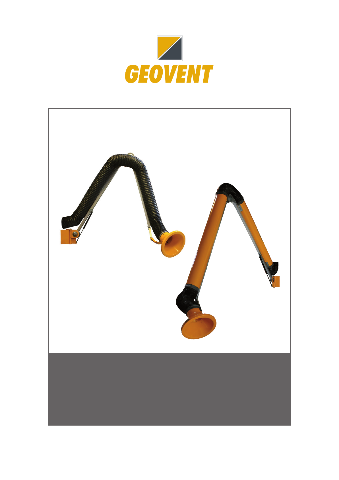
The GEOVENT ASA-3 Arm is the ideal Extraction Arm
for the extraction of welding smoke, grinding dust, fu-
mes, etc., where the well-being of the operator is in
focus with regard to lightness, ergonomics and efficien-
cy of the Arm.
The Extraction Arm is not suitable for the extraction of
aluminium dust, flour, textile dust nor sawdust or other
media, which are connected with danger of explosion,
without specific approval from Geovent A/S.
The hose may be damaged and leaky via outer loads,
e.g. by a screw driver. Avoid such load in order to safe-
guard a long life.
1.3 Handling
Always use gloves when handling. During transportati-
on all lifting must be in the arm. Note that it is possible
to pinch your fingers between the gas spring and arm.
When the arm is monuntet, it may only be handled by
the hood
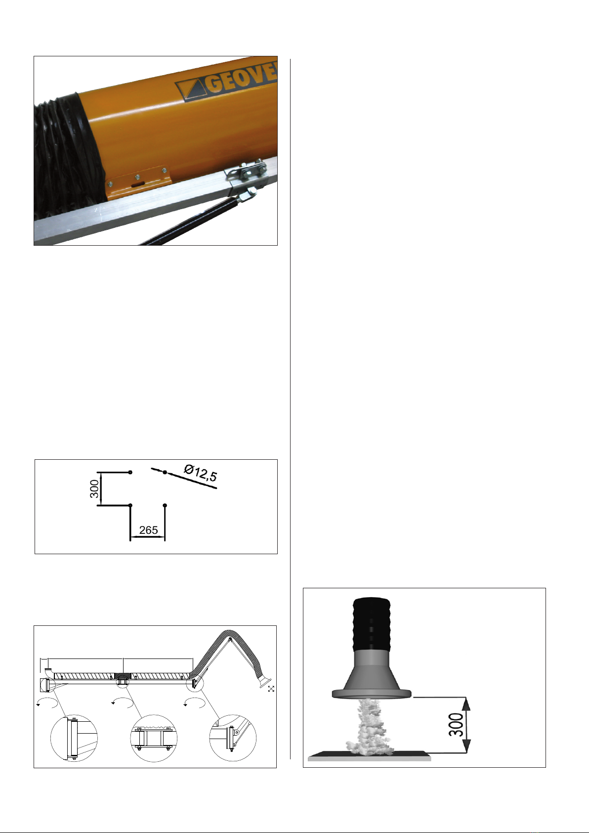
1.4 Technical data
ASA-3
Art no. Description Weight
ASA-01 2,0 m - ø 80 mm 9 kg
ASA-05 2,0 m - ø 80 mm - w. damper 9 kg
ASA-11 3,0 m - ø 80 mm 10 kg
ASA-15 3,0 m - ø 80 mm - w. damper 10 kg
ASA-02 2,0 m - ø 100 mm 9 kg
ASA-06 2,0 m - ø 100 mm - w. damper 9 kg
ASA-12 3,0 m - ø 100 mm 10 kg
ASA-16 3,0 m - ø 100 mm - w. damper 10 kg
ASA-22 4,0m - ø100 mm 12 kg
ASA-26 4,0m - ø100 mm - w. damper 12 kg
ASA-03 2,0 m - ø 125 mm 9 kg
ASA-07 2,0 m - ø 125 mm - w. damper 9 kg
ASA-4
med alu-rør
ASA-3
med slange