manuals.online logo
Brands
  1. Home
  2. •
  3. Brands
  4. •
  5. Gessi
  6. •
  7. Plumbing Product
  8. •
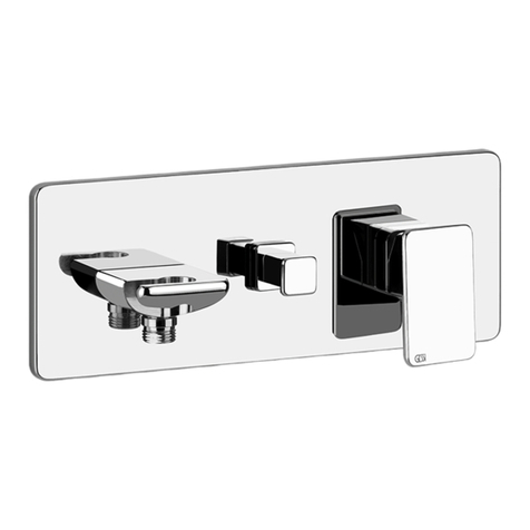
  9. Gessi 23447 User manual

Gessi 23447 User manual

Gessi SpA - Parco Gessi
13037 Serravalle Sesia (Vercelli) - Italy
Phone +39 0163 454111 - Facsimile +39 0163 459273
www.gessi.com - [email protected]
RETTANGOLO
Art. 23447
Art. 23448
Art. 23451
Art. 23452
PROGRAMMA TERMOSTATICO
THERMOSTATIC PROGRAM
PROGRAMME THERMOSTATIQUE
THERMOSTATISCHES PROGRAMM
PROGRAMA TERMOSTÁTICO
ПРОГРАММА ТЕРМОСТАТИЧЕСКИХ СМЕСИТЕЛЕЙ
2
Fig. 1
PRELIMINARI - PRE-INSTALLATION INFORMATION - PRÉALABLES -
VORBEREITUNG - PRELIMINARES - ПРЕДВАРИТЕЛЬНАЯ ПОДГОТОВКА
Dimensioni in mm - Measures in mm - Dimensions en mm - Maß im mm - Medidas en milímetros - Размеры выражены в мм
Art. 23447
Art. 23451
3
Fig. 1
PRELIMINARI - PRE-INSTALLATION INFORMATION - PRÉALABLES -
VORBEREITUNG - PRELIMINARES - ПРЕДВАРИТЕЛЬНАЯ ПОДГОТОВКА
Dimensioni in mm - Measures in mm - Dimensions en mm - Maß im mm - Medidas en milímetros - Размеры выражены в мм
Art. 23448
Art. 23452
4
Prima dell’installazione e messa in funzione
Attenzione! I tubi d’alimentazione devono essere sciacquati con cura prima dell’installazione del disposi-
tivo, in modo che non rimangano trucioli, residui di saldatura o canapa, o altre impurità all’interno dei tubi.
Attraverso tubazioni non sciacquate a fondo o attraverso la rete idrica generale, nel dispositivo possono
entrare corpi estranei in grado di danneggiare guarnizioni/o-ring.
Si raccomanda pertanto di dotare anche l’impianto generale di ltri.
E’ consigliabile installare il nuovo articolo osservando bene lo schema di installazione ideale proposto
in fig. 1
Before installation and setting to work
Attention! The feeding pipes have to be rinsed carefully before the installation of the device so that there
won’t remain shavings, sealing or hemp residues, or other impurities inside the pipes. Through pipes not
thoroughly rinsed or through the general water network, in the device foreign bodies can enter that could
damage gaskets /o-ring.
So lters should be installed also on the general system.
We recommend installing the new item in compliance with the installation layout as in fig. 1
Avant l’installation et la mise en fonction.
Attention! Les tuyaux d’alimentation doivent être rincés avec soin avant l’installation du dispositif, de
sorte que ils ne restent pas de copeaux, des restes de soudage ou de chanvre, ou d’autres impuretés à
l’intérieur des tuyaux. A travers les conduites non rincées à fond ou à travers le réseau hydrique général,
dans le dispositif peuvent entrer des corps étrangers à même de détériorer les gaines/o-ring. On recom-
mande ainsi d’installer des ltres également sur le système général.
Pour installer un nouvel article, il est conseillé d’observer attentivement le schéma d’installation idéal
proposé dans la fig. 1
Vor der Installation und Inbetriebnahme
Achtung! Bevor die Vorrichtung zu installieren, bitte spülen Sie die Zuleitungsröhre sorgfältig aus, um
alle Spannen, Schweiß- und. Hanfrückstände bzw. alle Verunreinigungen vom Inneren der Röhre zu
entfernen. Durch nicht sorgfältig gespülte Rohrleitungen bzw. durch das allgemeine Wassernetz können
Fremdkörper in den Korpen eintreten, die die Dichtungen bzw. die O-Ringe beschädigen können. Es ist
dann empfehlenswert, die allgemeine Anlage mit Filtern auszustatten.
Bei der Installation des neuen Artikels ist es empfehlenswert, den im Abb. 1 gezeigten Anweisungen zur
idealen Installation zu folgen.
Antes de la instalación y la puesta en función
¡Cuidado! Los tubos de alimentación tienen que ser enjuagados escrupulosamente antes de instalar el
dispositivo de manera que no haya virutas, residuos de soldadura o cáñamo u otras impurezas al interior
de los tubos. A través de los tubos no perfectamente enjuagados o de la red hídrica general pueden
entrar en el dispositivo unos cuerpos extraños que pueden dañar guarniciones, o-rings y/o. Les reco-
mendamos por lo tanto que instalen los ltros en la planta general también.
Les aconsejamos que instalen el nuevo artículo observando bien el esquema de instalación ideal pro-
porcionado en la fig. 1

Перед установкой устройства необходимо тщательно промыть водопроводные трубы,
чтобы в них не оставались стружка, шлак от сварки, лен или другие посторонние тела. Через
плохо промытые водопроводные трубы или через общую водопроводную сеть в устройство могут
попасть посторонние тела, способные повредить уплотнения и уплотнительные кольца.
Поэтому, рекомендуется оснастить фильтрами также и общую систему.
Рекомендуется устанавливать новый артикул, тщательно соблюдая идеальную схему установки,
предложенную на рис. 1.
PRELIMINARI - PRE-INSTALLATION INFORMATION - PRÉALABLES -
VORBEREITUNG - PRELIMINARES - ПРЕДВАРИТЕЛЬНАЯ ПОДГОТОВКА
5
COLD
Fig. 2
HOT
INSTALLAZIONE DEL CORPO MISCELATORE
Prima di iniziare assicurarsi che l’acqua della rete idrica sia chiusa.
Verificare che la posizione delle tubazioni rientri nei parametri indicati in figura, quindi avvitare gli eccentrici
ai tubi di alimentazione utilizzando della canapa o teflon per garantire la tenuta sui filetti (l’interasse finale
tra i due eccentrici dovrà essere di circa 150mm). L’errata connessione delle utenze d’ingresso pregiudica
il corretto funzionamento della cartuccia regolatrice di temperatura. Avvitare i dadi esagonali agli eccentrici
a muro, interponendo la guarnizione di tenuta. Scorrere i rosoni sulle guide no a raggiungere la parete
nita.
Attenzione! Vericare con l’ausilio di una livella che il corpo miscelatore sia stato posizionato perfetta-
mente in verticale ed inoltre assicurarsi che i rosoni, una volta posizionati contro la parete, consentano le
operazioni di pulizia dei ltri (vedi paragrafo “pulizia e/o sostituzione dei ltri” nella sezione dedicata alla
manutenzione).
MIXER BODY INSTALLATION
Before starting make sure the water network is off.
Check that the position of pipes is within the parameters in the figure, then screw the eccentrics on supply
pipes using hemp or Teflon to guarantee tightness on threads (the final center distance between the two
eccentrics shall be of around 150mm). The wrong connection of inlet devices disrupts proper operation of
temperature adjustment cartridge. Screw hexagonal nuts on wall eccentrics, laying the tightness gasket in
Fig. 2a
Ch. 30 mm
Ch. 30 mm
Ch. 24 mm
Ch. 24 mm
INSTALLAZIONE - INSTALLATION - INSTALLATION - INSTALLATION - INSTALACIÓN - УСТАНОВКА
Dimensioni in mm - Measures in mm - Dimensions en mm - Maß im mm - Medidas en milímetros - Размеры выражены в мм
6
between. Let round anges slide on rails down to the nished wall.
Warning! Check with a level that the mixer body is perfectly positioned vertically and also make sure that
round anges, once positioned against the wall, allow lters cleaning operations (see paragraph “lters cle-
aning and/or replacing” in the maintenance section).
INSTALLATION DU CORPS MÉLANGEUR
Avant de commencer s’assurer que l’alimentation du réseau de distribution est coupée.
Vérifier que la position des tuyauteries est conforme aux paramètres indiqués sur la figure, puis visser les
excentriques sur les tubes d’alimentation en utilisant du chanvre ou du téflon pour garantir l’étanchéité sur
les filets (la distance finale entre les axes des deux excentriques devra être d’environ 150mm). Un branche-
ment erroné des alimentations d’entrée compromet le fonctionnement correct de la cartouche régulatrice de
température. Visser les écrous hexagonaux sur les excentriques au mur, en interposant le joint d’étanchéité;
glisser les rosaces sur les guides jusqu’à leur contact avec la paroi nie.
Attention! Vérier avec l’aide d’un niveau que le corps mélangeur a été positionné parfaitement vertical
et s’assurer en outre que les rosaces, une fois positionnées contre la paroi, permettent les opérations de
nettoyage des ltres (voir paragraphe “nettoyage et/ou substitution des ltres” dans la section dédiée à
l’entretien).
INSTALLATION DES MISCHERKÖRPERS
Bevor zu starten, ist es sicherzustellen, dass die Wasserleitungen gesperrt sind.
Überprüfen Sie, dass die Position der Leitungen den im Bild angegebenen Parametern folgt, dann schrau-
ben Sie die Exzenterscheiben an die Versorgungsleitungen mittels Hanf oder Teflon an, um die Dichtheit
der Gewinden zu gewährleisten (am Ende soll der Achsabstand zwischen den zwei Exzenterscheiben etwa
150 mm. lang sein). Die falsche Verbindung der Wasser-Einleitungen kann die korrekte Funktionierung der
Kartusche zur Temperaturregelegung beeinträchtigen. Die Sechskantmutter an die wandinstallierten Exzen-
terscheiben anschrauben, und den Dichtungsring einfügen. Die Rosetten auf die Führungsschienen bis zur
Fertigwand laufen lassen.
Achtung! Stellen Sie mittels einer Libelle sicher, dass sich der Mischerkörper in vertikaler Position bendet,
und dass die Rosetten die Reinigung der Filter ermöglichen, nachdem sie an die Wand installiert worden
sind (siehe “Reinigung und/oder Wechsel der Filter” in dem Paragraph über die Instandhaltung).
INSTALACIÓN CUERPO MEZCLADOR
Antes de empezar asegúrense que el agua procedente de la red hídrica esté cerrada.
Verifiquen que la posición de las tuberías corresponda a los parámetros indicados en la figura, sucesiva-
mente atornillen los excéntricos a los tubos de alimentación utilizando cáñamo o teflón para asegurar la
hermeticidad de las roscas (la distancia final entre los dos excéntricos tendrá que ser de aproximadamente
150 mm). La conexión incorrecta de las líneas de entrada perjudica el correcto funcionamiento del cartucho
de regulación de la temperatura. Atornillen las tuercas hexagonales a los excéntricos en la pared, interpo-
niendo la junta de cierre. Hagan deslizar los orones sobre las guías hasta alcanzar la pared acabada.
¡Cuidado! Veriquen con la ayuda de un nivel que el cuerpo del mezclador se encuentre perfectamente
posicionado en vertical y, además, asegúrense que los orones, tras haber sido posicionados contra la
pared, no perjudiquen las operaciones de limpieza de los ltros (vean párrafo “Limpieza y/o sustitución de
los ltros” en la sección dedicada al mantenimiento).

Перед началом убедитесь, что вода из водопроводной сети перекрыта.
Убедитесь, что положение труб соответствует размерам, указанным на рисунке, после чего навинтите
эксцентрики на водопроводные трубы, используя лен или тефлон для обеспечения герметичности
резьбы (межосевое расстояние между двумя эксцентриками должно быть около 150 мм). Неправильное
подключение труб на входе отрицательно сказывается на исправности работы регулировочного
картриджа температуры. Привинтите шестигранные гайки к настенным эксцентрикам, устанавливая
уплотнительную прокладку. Сдвиньте розетки по направляющим вплоть до отделанной стены.
 Проверьте по уровню, что корпус смесителя правильно установлен по вертикали, кроме
того, убедитесь, что розетки, после того, как они были приложены к стене, позволяют прочищать
фильтры (см. параграф “чистка и/или замена фильтров” в разделе, посвященном обслуживанию).
INSTALLAZIONE - INSTALLATION - INSTALLATION - INSTALLATION - INSTALACIÓN - УСТАНОВКА
7
Fig. 3
INSTALLAZIONE SUPPORTO SOFFIONE
Utilizzare la maschera di foratura come mostrato in figura per individuare i punti in cui effettuare i fori per
il fissaggio a parete. Per fare questo è importante che i rosoni del corpo dell’articolo siano ben appoggiati
alla parete in modo tale da permettere alla maschera di foratura di essere il più precisa possibile. Togliere
la maschera di foratura e realizzare i fori profondi minimo 50mm con una punta Ø8mm per inserirvi i tas-
selli in dotazione. Applicare le boccole ovali alla parete, facendo coincidere i fori delle placchette con quelli
dei tasselli. Fissare con le apposite viti in dotazione. Introdurre la colonna doccia sul corpo fino a battuta
meccanica.
SHOWER HEAD SUPPORT INSTALLATION
Use the drilling jig as shown in the picture to individuate the points where to make the drills for the wall
mounting. To do this, it is important that the covering rings of the body of the item are well laid against the
wall, in order to obtain maximum accuracy from the drilling jig. Remove the piercing jig and make holes
deep at least 50mm with a drill Ø8mm to insert the plugs supplied. Apply the oval bushes to the wall, being
match the holes of the plates with those of the dowels. Tighten with the supplied screws. Insert the shower-
rod on the body until reaching a mechanical stop.
INSTALLATION DU SUPPORT DE LA POMME
Utiliser le gabarit de forage comme il est montré dans la figure pour déterminer les points ou il faut effectuer
les trous pour le fixage à la paroi. Pour faire cela il est important que les roses du corps de l’article sont
bien appuyés à la paroi pour permettre au gabarit de forage pour être la plus précise possible. Retirer le
gabarit de perçage et pratiquer des trous profonds au minimum de 50mm avec une pointe Ø8mm pour y
insérer les chevilles fournies en dotation. Applier les boucles oval à mur en faisant coïncider parfaitement
B C
D
E
Ø8x50
A
INSTALLAZIONE - INSTALLATION - INSTALLATION - INSTALLATION - INSTALACIÓN - УСТАНОВКА

8
les trous de les plaques avec les trous des tasseaux. Fixer avec ses correspondant vis fourni. Inserér la
tige de douche sur le corps et glisser jusq’ á percevoir une battue mechanique.
INSTALLATION DER STÜTZE FÜR DEN BRAUSEKOPF
Wie gezeigt, verwenden Sie die Bohrschablone, um die für die Wandbefestigung notwendigen Bohrung-
spunkte zu lokalisieren. Zu diesem Zweck, sollen die Scheiben des Teilkörpers an der Wand befestigt sein,
so dass die höchste Genauigkeit der Bohrschablone gewährleistet wird. Die Bohrschablone ausziehen
und die Löcher mit einer mindesten Tiefe von 50mm durch einen Bohrer von Ø8mm anbohren, um die
serienmäβigen Dübel einzufügen. Befestigen Sie die ovale Buchse an die Wand, indem Sie die Löcher
des Plättchens mit denen der Dübel zusammenfallen lassen. Befestigen Sie die Buchse mit den geliefer-
ten Schrauben. Setzen Sie die Duschenstange auf dem Körper bis das Erreichen eines mechanischen
Anschlags ein.
INSTALACIÓN SOPORTE FLORÓN
Utilicen la plantilla de horadación, como indicado en la figura, para individuar los puntos en los cuales
hay que realizar los huecos para la fijación a la pared. Para hacer esto es importante que los florones del
cuerpo del artículo queden bien apoyados a la pared para que la plantilla de horadación pueda utilizarse
de la manera más precisa posible. Quiten la plantilla de horadación y realicen los huecos profundos, como
mínimo 50mm, con una broca de Ø8mm para introducir los tacos incluidos en el suministro. Apliquen los
bujes oval a la pared de manera que los huecos de las plaquitas correspondan a aquellos de los tacos.
Fijen con los tornillos incluidos en el suministro. Insertar la columna-ducha entre el cuerpo fin de percibir
un parado mecánico.

Используйте кондуктор для сверления, как показано на рисунке, чтобы определить точки для
крепления к стене. Для этого необходимо, чтобы розетки корпуса изделия хорошо прилегали к
стене, чтобы кондуктор сверления был как можно более точным.
Снимите кондуктор для сверления и просверлите отверстия глубиной минимум 50 мм сверлом
Ø8 мм, чтобы вставить туда входящие в комплект дюбели. Установите овальные втулки на стену,
совмещая отверстия накладок с дюбелями. Закрепите входящими в комплект винтами. Наденьте
душевую колонну на корпус до упора.
INSTALLAZIONE - INSTALLATION - INSTALLATION - INSTALLATION - INSTALACIÓN - УСТАНОВКА
9
Fig. 4
1
2
3
4
5
3 mm
3 mm
3 mm
INSTALLAZIONE - INSTALLATION - INSTALLATION - INSTALLATION - INSTALACIÓN - УСТАНОВКА
10
INSTALLAZIONE SUPPORTO SOFFIONE
Dopo aver inserito la colonna porta soffione sul perno presente sul corpo fino a battuta sul fondo, inserire la
boccola ovale sul supporto della colonna, interponendo il rosone di bloccaggio. Avvicinare la colonna alla
boccola a muro e fissarla con le viti in dotazione. Regolare l’inclinazione della colonna scorrendo l’asta di
supporto nel rosone. Identificare la posizione perfettamente verticale aiutandosi con una livella e bloccare
la colonna doccia con la vite in dotazione.
SHOWER HEAD SUPPORT INSTALLATION
Insert the bush over the support of the column, interposing the finishing hood. Insert the headshower holder
rod on the pin placed in the upper part of the body, until reaching the bottom. Bring the column closer to
the wall oval bushand fix it with the supplied screw. Adjust the slant of the column by sliding the support
rod onto cover plate. Look for the perfecly vertical position helping yourself with a bubble-air level and fix
the column with the supplied screw.
INSTALLATION DU SUPPORT DE LA POMME
Inserér la boucle ovale sur le support de la tige, en interposant la rosette de finissage. Introduire la colonne
porte-douche sur le pivot présent sur le corps fin á la battue á fond. Approcher la colonne a la boucle ovale
et la fixer avec ses vis fournie. Régler l’inclinaison de la colonne en coulant la tige de support dans la ro-
sette. Identifiér la position parfaitement verticale en s’aidant avec un niveau et bloquer la colonne douche
avec la vis fourni.
INSTALLATION DER STÜTZE FÜR DEN BRAUSEKOPF
Setzen Sie die Busch über der Unterstützung der Spalte ein und die beendenhaube vermitteln. Stellen Sie
die ovale Buchse ins Zentrum des vorher lokalisierten Punktes, und markieren Sie mit einem Bleistift die
genaue Position der Bohrungen. Nähern Sie die Säule an die ovale Buchse an, und befestigen Sie die mit
den gelieferten Schrauben. Verstellen Sie die Neigung der Säule, in dem Sie den Ablagestab in der Schei-
be laufen lassen. Finden Sie die senkrechte Position mit Hilfe einer Wasserwaage, und blockieren Sie die
Duschsäule durch die gelieferte Schraube.
INSTALACIÓN SOPORTE FLORÓN
Alojen el grupo de fijación sobre la varilla de la columna ducha, niterponinedo el rosetón de acabado.
Introduzcan la columna que lleva el pomo de ducha en el pivote que se encuentra sobre el cuerpo hasta
el fondo. Acerquen la columna al buje oval y fíjenla con los tornillos incluidos en el suministro. Regulen la
inclinación de la columna haciendo deslizar la varilla de soporte al interior del florón. Identifiquen la posi-
ción perfectamente vertical ayudándose con un nivel y bloqueen la columna ducha con el tornillo incluido
en el suministro.

Надев до упора колонну душевой лейки на палец, присутствующий на корпусе, установите овальную
втулку на опору колонны, проложив блокировочную розетку. Подведите колонну к настенной втулке
и закрепите ее поставляемыми винтами. Отрегулируйте наклон колонны, смещая опорную штангу в
розетке. Определите строго вертикальное положение при помощи уровня, и заблокируйте душевую
колонну поставляемым винтом.
INSTALLAZIONE - INSTALLATION - INSTALLATION - INSTALLATION - INSTALACIÓN - УСТАНОВКА

Надев до упора колонну душевой лейки на палец, присутствующий на кор-
пусе, установите овальную втулку на опору колонны, проложив блокиро-
вочную розетку. Подведите колонну к настенной втулке и закрепите ее пос-
тавляемыми винтами. Отрегулируйте наклон колонны, смещая опорную
штангу в розетке. Определите строго вертикальное положение при помощи
уровня, и заблокируйте душевую колонну поставляемым винтом.
11
Fig. 5
1
2
INSTALLAZIONE - INSTALLATION - INSTALLATION - INSTALLATION - INSTALACIÓN - УСТАНОВКА
12
INSTALLAZIONE SOFFIONE E DOCCETTA
Avvitare il sofone al raccordo avendo cura di posizionare la guarnizione fornita. Collegare l’estremità
del essibile con la calotta più corta (ssa) all’uscita del deviatore e l’estremità con la calotta più lunga
(girevole) alla doccetta. Non è necessario interporre guarnizioni, poiché già incorporate nelle calotte del
essibile stesso.
INSTALLATION OF SHOWER HEAD AND HAND SHOWER
Screw the head shower in the connection taking care to position the supplied washer. Connect the
extremity of the exible with shortest vault (xed) to the diverter outlet and the extremity with the longest
vault (swivelling) to the shower-head. Is not needed to interpose washers, ‘cause there is just inbuilt in the
extremities of the exible.
INSTALLATION POMME ET DOUCHETTE
Nous vous prions de bien vouloir visser la pomme de douche au raccord en interposant entre eux le joint.
Connecter l’extrémitè du exible avec la calotte plus courte (xe) à la sortie de l’inverseur et l’autre extré-
mité avec la calotte plus longue (pivotant) à la douchette. Il n’est pas nécessaire de rajouter des joints car
ils sont déjà incorporés dans les calottes du exible.
INSTALLATION VON BRAUSKOPF UND HANDBRAUSE
Schrauben Sie die Kopfbrause mit dem Verbindungsrohr ein, und sorgen Sie dafür, dass die gelieferte
Dichtung gelegt wird. Verbinden Sie das Ende des Schlauches mit der kürzeren Kappe (x) mit dem
Ausgang der Umstellung, und das Ende des Schlauchs mit dem längeren Kappe (drehbar) mit der Han-
dbrause. Keine Dichtungen sind dazwischen zu legen, da sie sich schon in den Kappen des Schlauches
benden.
INSTALACIÓN POMO DE DUCHA Y DUCHA-TELÉFONO
Atornillen el pomo de ducha a la conexión correspondiente cuidando con posicionar correctamente la junta
suministrada. Conecten la extremidad del exo con el casquete más corto (jo) a la salida del desviador
y la extremidad con el casquete más largo (rotatorio) a la ducha-teléfono. No es necesario interponer las
juntas ya que están incorporadas en los casquetes del mismo exo.

Привинтите душевую лейку к штуцеру, не забывая устанавливать входящее в комплект
уплотнение. Подключите конец гибкого шланга с более короткой колодкой (фиксированной) к
выходу распределителя, а конец с более длинной колодкой (поворотной) к ручному душу. Нет
необходимости в установке уплотнений, так как они уже установлены в колодки гибкого шланга.
INSTALLAZIONE - INSTALLATION - INSTALLATION - INSTALLATION - INSTALACIÓN - УСТАНОВКА

13
FUNZIONAMENTO DEL MISCELATORE TERMOSTATICO
Avviare e regolare a piacere l’erogazione ruotando la maniglia a sinistra (A). Se la regolazione della
temperatura è stata eseguita correttamente, l’acqua uscirà alla temperatura di circa 38° C (A1). Ruotare la
maniglia a destra in senso orario per ottenere una diminuzione della temperatura (A2); premere il pulsante
di sicurezza e ruotare la maniglia in senso antiorario per ottenere un aumento della temperatura (A3).
THERMOSTATIC MIXER WORKING
Start and adjust as you like the distribution, by turning the left handle (A). If the temperature adjustment
was been well carried out, the water will flows at working temperature of 38° C (A1). Turn the right handle
clockwise in order to obtain a temperature decreasing (A2). Push the safety button and turn the handle
counterclockwise in order to obtain a temperature increasing (A3).
FUNCTIONEMMENT DU MÉLANGEUR THERMOSTATIQUE
Amorcer et régler au plaisir le débit en tournant la poignée á gauche (A). Si la régulation de la temperature
est ête efectué correctement, l’eau sortira a la temperature de dans les 38° (A1). Tourner la pognée á droite
dans le sens des aiguilles d’une montre pour obtenir une diminution de la temperature. (A2); appuyer sur
le bouton de sûreté et tourner la poignée dans le sens contraire à celui des aiguilles d’une montre pour
obtenir une augmentation de la température (A3).
BETRIEB DES THERMOSTATISCHEN HEBELMISCHERS
Starten Sie die Wasserversorgung und verstellen Sie die auf Wunsch durch Drehung des Handgriffs nach
links (A). Wenn die Temperatur ordnungsgemäß verstellt worden ist, wird das Wasser mit einer Temperatur
von etwa 38° C ausgehen (A1). Drehen Sie den Hangriff nach rechts im Uhrzeigersinn, um die Temperatur
zu senken (A2); drücken Sie den Sicherheitsschalter und drehen Sie den Handgriff gegen Uhrzeigersinn,
um die Temperatur zu erhöhen (A3).
A1
A2
A1
A3
38°
38° => 30°
38° => 50°
Fig. 6A
USO - USE - USAGE - GEBRAUCH - USO - ИСПОЛЬЗОВАНИЕ
14
FUNCIONAMIENTO DEL MEZCLADOR TERMOSTÁTICO
Abran y regulen según Su deseo la erogación girando la maneta a la izquierda (A). Si la regulación de la
temperatura se ha efectuado correctamente el agua saldrá con una temperatura de aproximadamente 38°
C (A1). Giren la maneta a la derecha en el sentido de las agujas del reloj para obtener una disminución de
la temperatura (A2); Pulsen el botón de seguridad y giren la maneta en el sentido contrario a las agujas del
reloj para obtener un aumento de la temperatura (A3).

Включите воду и отрегулируйте по вашему усмотрению левую ручку (А). Если регулировка
температуры выполнена правильно, вода будет вытекать при температуре около 38°C (А1).
Поверните ручку вправо, по часовой стрелке, чтобы достичь снижения температуры (А2). Нажмите
предохранительную кнопку и поворачивайте ручку против часовой стрелки для повышения
температуры (А3).
USO - USE - USAGE - GEBRAUCH - USO - ИСПОЛЬЗОВАНИЕ
15
FUNZIONAMENTO DEL DEVIATORE
Il dispositivo permette la deviazione del usso dell’acqua alla doccetta collegata al monocomando. Per
azionare il deviatore è sufciente avviare la normale erogazione dell’acqua e tirare il pomolo verso l’ester-
no (B1). In questo modo l’acqua uscirà dalla doccetta. Per ripristinare la condizione iniziale basterà inter-
rompere l’erogazione agendo sulla maniglia e il pomolo ritornerà automaticamente in posizione di riposo
(B2).
REGOLAZIONE DELL’ALTEZZA DEL SUPPORTO DOCCIA (SOLO ART. 23451-23452)
Per regolare l’altezza del supporto della doccetta, allentare il pomolo e scorrere il blocchetto no alla posi-
zione desiderata. Bloccarlo in posizione ruotando il pomolo nel verso opposto.
DIVERTER OPERATION
The device allows the deviation of the water ux towards an handshower, connected to the single-lever
mixer. In order to operate the diverter it’s enough to run the normal water distribution and pull the knob
towards outside (B1). In this way the water will ow from the hand-shower. To restore the initial condition,
it will be sufcient to stop the water distribution by means of the handle; the knob automatically will return
to the rest position (B2).
HAND-SHOWER HOLDER ADJUSTMENT (ONLY FOR ART. 23451-23452)
To adjust the handshower holder height, loosen the knob and slide the block until desired height. Lock it in
position by turning the knob in the reverse sense.
FONCTIONNEMENT DU DEVIATEUR
Le dispositif permet la déviation du ux d’eau vers une douchette, connecté au monocommande. Pour
actionner le déviateur, il est sufsant de commencer la distribution normale de l’ eau en tirant le pommeau
vers l’exterieur (B1). De cette façon l’eau sortira de la douchette. Pour rétablir la condition initiale, il faudra
interrompre la distribution de l’eau avec l’aide de la poignée et le pommeau retournera automatiquement
a la position de repos (B2).
B1 B2 C
“23451-23452 only”
Fig. 6B Fig. 6C
USO - USE - USAGE - GEBRAUCH - USO - ИСПОЛЬЗОВАНИЕ
16
RÉGULATION DE L’HAUTEUR DE LE SUPPORT-DOUCHE (SEULEMENT POUR ART. 23451-23452)
Pour régler l’hauteur de le support de la douchette, if faut desesser le pommeau et faire glisser le bloquet
n á la position desirée. Bloquer en position en tournant le pommeau en verse contraire.
FUNKTION VOM UMSTELLVENTIL
Diese Vorrichtung ermöglicht das Ablenken des Wasserusses zu einer Handusche, die mit der Einhebel-
Mischbatterie verbunden ist. Um das Umstellventil zu betätigen, braucht man nur die übliche Wasserab-
gabe zu öffnen und zieht dann den Kugelgriff zu sich hin (B1). Auf diese Weise wird das Wasser über die
Dusche abgegeben. Um die Ausgangsbedingungen wieder herzustellen ist es ausreichend, die Wasse-
rabgabe zu unterbrechen, indem man den Hebel betätigt und der Kugelgriff kehrt automatisch in seine
Ruhestellung zurück (B2).
HÖHENVERSTELLUNG DER STÜTZTE DER HANDBRAUSE (NUR ART. 23451-23452)
Um die Höhe der Stützte der Handbrause zu verstellen, schrauben Sie den Hebelknopf los, und lassen Sie
das Endmaß bis zur gewünschten Position laufen. Blockieren Sie es in der gewünschten Position, indem
Sie den Hebelknopf in die Gegenrichtung drehen lassen.
FUNCIONAMIENTO DEL DESVIADOR
El dispositivo permite la desviación del ujo del agua a una ducha-teléfono conectada al monomando.
Para accionar el desviador es suciente empezar la erogación normal del agua y tirar el pomo hacia l’ex-
terno (B1). De esta forma, el agua saldrá de la ducha-teléfono. Para restablecer la condición inicial será
suciente interrumpir la erogación del agua con la ayuda de la maneta y el pomo volverá automáticamente
a la posición de reposo (B2).
REGULACIÓN DEL ALTO DEL SOPORTE DUCHA (SÓLO REF. 23451-23452)
Para regular el alto del soporte de la ducha teléfono, aojen el pomo y hagan deslizar el bloque hasta la
posición deseada. Bloqueen la posición girando el pomo en el sentido contrario.

Это устройство обеспечивает переключение потока воды на душ, подключенный к смесителю. Для
включения распределителя достаточно включить обычную подачу воды и потянуть ручку наружу
(В1). В этом случае вода будет выходить из ручного душа. Для восстановления начального состояния
достаточно будет прекратить подачу воды ручкой, после чего рукоятка автоматически вернется в
исходное положение (В2).

Для регулировки высоты суппорта ручного душа ослабьте рукоятку и сместите блок до необходимого
вам положения. Закрепите его в нужном положении, вращая ручку в противоположном
направлении.
USO - USE - USAGE - GEBRAUCH - USO - ИСПОЛЬЗОВАНИЕ
17
- Svitare mediante una chiave a brugola i grani che ssano il blocchetto di sostegno e slare il
blocchetto stesso dal supporto.
- Unscrew the dowels which x the hand-shower holder block by means of an Allen wrench and
lift off the same block from its support.
- Dévisser au moyen d’une clé anglaise les grains qui xent le petit bloc de soutien et enlever
le bloc même de son support.
- Schrauben Sie die Befestigungsstifte des Ablage-Endmaßes mit einem Inbusschlüssel ab und
ziehen Sie das Endmaß aus seiner Ablage heraus.
- Destornillen con la ayuda de una llave de allén las clavijas de jación que detienen el bloque
de soporte y suelten el mismo bloque del soporte.
- Отвинтите шестигранным ключом стопорные винты, крепящие опорный блок, и снимите
его с суппорта.
- Svitare il supporto del deviatore, facendo attenzione a non danneggiare gli OR.
comprimere e trattenere il deviatore verso l’interno per poter svitare agevolmente il
pomolo.
- Loosen the diverter support, being care to do not damage the ORings. Compact and
hold the diverter device into the seat, in order to can easily unscrew the knob.
- Devisser le support de l’invérseur , en faisant attention de ne pas endommager les
O-rings. Comprimer et retenir le dispositif de l’inverseur vers l’interiéur pour devisser
facilement le pommeau.
- Schrauben Sie die Unterlage der Umstellung ab, ohne die O-Ringe zu beschädigen.
Drücken Sie die Umstellung und sorgen Sie dafür, dass sie im Inneren bleibt, um den
Hebelknopf leicht abschrauben zu können.
- Destornillen el soporte del desviador cuidando con no dañar los OR. Compriman y
desplacen el desviador hacia el interior para destornillar el pomo fácilmente.
- Отвинтите суппорт распределителя, обращая внимание на то, чтобы не повредить
уплотнительные кольца. Нажмите внутрь и удерживайте распределитель, чтобы
легко отвинтить рукоятку.
- Estrarre il dispositivo deviatore danneggiato e sostituirlo procedendo nella sequenza inversa.
Attenzione: la guarnizione a labbro indicata a disegno potrebbe rimanere incastrata sul fondo
durante l’estrazione del deviatore. Nel caso estrarla con una pinzetta.
- Leave the damaged diverter device and replace it by reversing the procedure. Attention: the lip-
washer shown in the picture could get stuck in the bottom during the extractio. In case extract it
with tweezers.
- Extraire le dispositif de l’invérseur endommagé et remplacer procedant en la séquence contraire.
Attentión: la jointe á lévre indiquée sur le dessin pourrait rester encastrée en fond pendant
l’estractión de l’invérseur. Dans le cas pouvez extraire-le avec une pincette.
- Ziehen Sie die beschädigte Umstellung heraus und ersetzen Sie die, indem Sie die Folge der
erledigten Operationen umkehren. Achtung! Die Lippendichtung, die in den Zeichnungen gezeigt ist,
könnte sich bei dem Herausziehen der Umstellung am Boden verklemmen. In diesem Fall, ziehen
Sie die durch eine Zange heraus.
- Extraigan el dispositivo desviador dañado y sustitúyanlo siguiendo el procedimiento inverso.
Cuidado: la junta de labios indicada en la gura podría quedarse encastrada en el fondo durante la
extracción del desviador. En este caso extráiganla con unas pinzas.
- Извлеките поврежденное устройство распределителя и замените его, действуя в обратной
последовательности. Внимание: Показанное на рисунке манжетное уплотнение может
застрять внизу во время извлечения распределителя. В этом случае извлеките его пинцетом.
Ch. 23 mm
Fig. 7
Fig. 8
Fig. 9
2.5 mm
MANUTENZIONE - MAINTENANCE - ENTRETIEN - WARTUNG - MANUTENCIÓN - ОБСЛУЖИВАНИЕ
18
SOSTITUZIONE DEL VITONE
Prima di effettuare tale operazione assicurarsi che l’acqua della rete idrica sia chiusa.
Togliere il tappino in nitura facendo attenzione a non danneggiarlo e svitare il grano di ssaggio utilizzando una
chiave a brugola. Estrarre quindi la maniglia slandola dal vitone. Inne svitare il vitone con una chiave da 17 mm
e sostituirlo. Riassemblare i particolari con il procedimento inverso.
HEADVALVE REPLACEMENT
Before carrying out this operation make sure that water of the water mains is closed.
Remove the nish plug paying attention not to damage it and unscrew the screw using an Allen wrench. Lift the
handle and take it out form the headvalve. Unscrew then the headvalve using a 17 mm wrench and replace it.
Reinstall all the details, proceeding in opposite order.
SUBSTITUTION DE LA TÊTE
Avant d’effectuer cette opération, il faut s’assurer que l’eau du réseau hydrique est fermée.
Enlever le bouchon en finition faisant attention à ne pas l’abîmer et dévisser les grains de fixage en utilisant une
clé à griffe. Soulever la poignée en la désenfilant de la tête. Dévisser, enfin, la tête en utilisant une clé de 17 mm
et substituer-le. Remonter-le tout avec le procédé inverse.
AUSTAUSCHEN DES OBERTEILS
Bevor man diese Tätigkeit durchführt, muß man sich vergewissern, dass die Versorgung zum Wassernetz
unterbrochen ist.
Den Endverschluss herausnehmen, ohne ihn zu beschädigen, und den Bolzen abschrauben wobei man ihn vom
Oberteil abzieht. Schließlich das Oberteil mit einem 17 mm Schlüssel abschrauben und mit einem neuen
ersetzen. Dann die Einzelheiten in umgekehrter Vorgehensweise erneut montieren.
SUSTITUCIÓN DE LA MONTURA
Antes de efectuar dicha operación asegúrense que el agua de la red hídrica esté cerrada.
Quiten el taponcito de acabado cuidando con no dañarlo y destornillen la clavija de fijación utilizando una llave
de allén. Levanten, por lo tanto, la maneta sacándola de la montura.Finalmente destornillen la montura con una
llave de 17 mm y sustitúyanla. Vuelva a ensamblar los detalles según el procedimiento inverso.

Перед выполнением этой операции убедитесь, что вода из водопроводной сети перекрыта.
Снимите декоративную заглушку, обращая внимание на то, чтобы не повредить ее, и отвинтите крепление,
используя шестигранный ключ. Затем снимите ручку с вала буксы. Наконец, отвинтите буксу ключом на 17
мм и замените ее. Соберите все компоненты в обратной последовательности.
Fig. 13
2.5 mm
Ch. 17 mm
2.5 mm
MANUTENZIONE - MAINTENANCE - ENTRETIEN - WARTUNG - MANUTENCIÓN - ОБСЛУЖИВАНИЕ
19
SOSTITUZIONE DELLA CARTUCCIA TERMOSTATICA
Prima di effettuare tale operazione assicurarsi che l’acqua della rete idrica sia chiusa.
Togliere il tappino in nitura facendo attenzione a non danneggiarlo e svitare il utilizzando una chiave
a brugola, estrarre quindi la maniglia slandola dalla cartuccia. Svitare la ghiera di tenuta ed estrarre la
cartuccia dal corpo termostatico. Introdurre la cartuccia nuova avendo cura di far coincidere la tacca in
rilievo della stessa con quella che si trova sul corpo del monocomando, quindi effettuare inversamente il
procedimento per ssare la nuova cartuccia al monocomando mantenendo i riferimenti corretti.
THERMOSTATIC CARTRIDGE REPLACEMENT
Before carrying out this operation make sure that water of the water mains is closed.
Remove the finish plug paying attention not to damage it and unscrew the screw using an Allen wrench,
take out the handle , removing it from the cartridge . Unscrew the ring nut and take the cartridge out form
the thermostatic body. Insert the new cartridge paying attention to match the reference notch with the one
present on the body of the single operation group, then carry out the opposite procedure to fix the new
cartridge to the single operation group keeping the proper references.
SUBSTITUTION DE LA CARTOUCHE THERMOSTATIQUE
Avant d’effectuer cette opération, vérifier que l’eau du réseau hydrique est fermée.
Enlever le bouchon en finition faisant attention à ne pas l’abîmer et dévisser les grains de fixage utilisant
une clé à griffe, extraire en suite la poignée en la soulevant de la cartouche . Dévisser la virole d’étanchéité
et extraire la cartouche du corps thermostatique. Introduire la cartouche neuve en ayant soin de faire
coïncider l’encoche en relief avec celle qui se trouve sur le corps de la mono-commande, ensuite effectuer
inversement le procédé pour fixer la nouvelle cartouche à la mono-commande en maintenant les références
correctes.
AUSTAUSCHEN DER THERMOSTATISCHEN KARTUSCHE
Bevor man diese Tätigkeit durchführt, muß man sich vergewissern, dass die Versorgung zum Wassernetz
unterbrochen ist.
Den Endverschluss herausnehmen, ohne ihn zu beschädigen, und den Bolzen (A) abschrauben, dann
den Griff von der Kartusche abziehen. Die Nutmutter losschrauben und die Kartusche aus dem
thermostatischen Körper herausziehen. Die neue Kartusche einsetzen wobei darauf zu achten ist, dass die
hervorstehende Kerbe dieser mit der Kerbe, die sich auf dem Körper der Einhebel-Mischbatterie bendet,
übereinstimmt. Dann führt man die beschriebenen Tätigkeiten in umgekehrter Abfolge durch, um die neue
Kartusche an der Einhebel-Mischbatterie zu befestigen, wobei die Bezugspunkte korrekt beibehalten
werden müssen.
Fig. 14
Ch. 27 mm
2.5 mm
MANUTENZIONE - MAINTENANCE - ENTRETIEN - WARTUNG - MANUTENCIÓN - ОБСЛУЖИВАНИЕ
20
SUSTITUCIÓN DEL CARTUCHO TERMOSTÁTICO
Antes de sustituir el cartucho, asegúrense el agua de la red hídrica esté cerrada.
Quiten el taponcito de acabado cuidando con no dañarlo y destornillen la clavija de fijación utilizando una
llave de allén, extraigan la maneta sacándola del cartucho . Destornillen la virola de cierre y extraigan
el cartucho del cuerpo termostático. Introduzcan el cartucho nuevo, cuidando con que la muesca que se
encuentra sobre el mismo cartucho, coincida con aquella del monomando. Para fijar el nuevo cartucho al
monomando, manteniendo las referencias correctas, efectúen el procedimiento inverso.

Перед выполнением этой операции убедитесь, что вода из водопроводной сети перекрыта.
Снимите декоративную накладку, обращая внимание на то, чтобы не повредить ее, и отвинтите
стопорный винт шестигранным ключом, после чего снимите ручку с картриджа. Отвинтите крепежную
круглую гайку и снимите картридж с корпуса термостатического смесителя. Установите новый
картридж, обращая внимание на то, чтобы совместить его выступающую метку с меткой, которая
находится на корпусе однокомандного смесителя, после чего выполните процедуры в обратной
последовательности для установки нового картриджа на однокомандный смеситель, соблюдая
правильность установки.
MANUTENZIONE - MAINTENANCE - ENTRETIEN - WARTUNG - MANUTENCIÓN - ОБСЛУЖИВАНИЕ

Other manuals for 23447

1

This manual suits for next models

3

Other Gessi Plumbing Product manuals

Gessi 54092 User manual

Gessi

Gessi 54092 User manual

Gessi CONO 45079 User manual

Gessi

Gessi CONO 45079 User manual

Gessi 39808 User manual

Gessi

Gessi 39808 User manual

Gessi OVALE 26900 User manual

Gessi

Gessi OVALE 26900 User manual

Gessi OVALE 21631 User manual

Gessi

Gessi OVALE 21631 User manual

Gessi 30651 User manual

Gessi

Gessi 30651 User manual

Gessi ISPA 41138 User manual

Gessi

Gessi ISPA 41138 User manual

Gessi 32849 User manual

Gessi

Gessi 32849 User manual

Gessi RETTANGOLO J 20706 Troubleshooting guide

Gessi

Gessi RETTANGOLO J 20706 Troubleshooting guide

Gessi INCISO 58105 User manual

Gessi

Gessi INCISO 58105 User manual

Gessi VIA TORTONA 18611 User manual

Gessi

Gessi VIA TORTONA 18611 User manual

Gessi OXYGENE 24931 User manual

Gessi

Gessi OXYGENE 24931 User manual

Gessi 23411 User manual

Gessi

Gessi 23411 User manual

Gessi RETTANGOLO 20035 Troubleshooting guide

Gessi

Gessi RETTANGOLO 20035 Troubleshooting guide

Gessi goccia 33732 Troubleshooting guide

Gessi

Gessi goccia 33732 Troubleshooting guide

Gessi RETTANGOLO 30988 User manual

Gessi

Gessi RETTANGOLO 30988 User manual

Gessi INCISO 58142 User manual

Gessi

Gessi INCISO 58142 User manual

Gessi MIMI 36501 Troubleshooting guide

Gessi

Gessi MIMI 36501 Troubleshooting guide

Gessi EQUILIBRIO 52002 User manual

Gessi

Gessi EQUILIBRIO 52002 User manual

Gessi RETTANGOLO XL 26185 User manual

Gessi

Gessi RETTANGOLO XL 26185 User manual

Gessi goccia 35373 User manual

Gessi

Gessi goccia 35373 User manual

Gessi Rettangolo 20132 User manual

Gessi

Gessi Rettangolo 20132 User manual

Gessi SOGNI 57961 User manual

Gessi

Gessi SOGNI 57961 User manual

Gessi ELEGANZA 46103 User manual

Gessi

Gessi ELEGANZA 46103 User manual

Popular Plumbing Product manuals by other brands

Toto RYOHAN TEL3GMY installation manual

Toto

Toto RYOHAN TEL3GMY installation manual

RUVATI RVH6222 installation guide

RUVATI

RUVATI RVH6222 installation guide

Abode Belfast AX4046 manual

Abode

Abode Belfast AX4046 manual

Symmons Elm SLC5512PP Operation & maintenance manual

Symmons

Symmons Elm SLC5512PP Operation & maintenance manual

Creda Aquawave White Installation and user guide

Creda

Creda Aquawave White Installation and user guide

Olympia K-5040 Installation and Maintenance

Olympia

Olympia K-5040 Installation and Maintenance

fine fixtures GRAND GD18 installation instructions

fine fixtures

fine fixtures GRAND GD18 installation instructions

ProFlo PFWSC9860CP installation instructions

ProFlo

ProFlo PFWSC9860CP installation instructions

Kohler Reve K-5148-8 quick start guide

Kohler

Kohler Reve K-5148-8 quick start guide

Graff Oscar GN-4853 installation instructions

Graff

Graff Oscar GN-4853 installation instructions

PolyJohn PS14 Series Operation & maintenance guide

PolyJohn

PolyJohn PS14 Series Operation & maintenance guide

Hans Grohe M415-H160 Series Instructions for use/assembly instructions

Hans Grohe

Hans Grohe M415-H160 Series Instructions for use/assembly instructions

SFA SANICUBIC 2 GR installation instructions

SFA

SFA SANICUBIC 2 GR installation instructions

Hans Grohe AXOR 26434180 Instructions for use/assembly instructions

Hans Grohe

Hans Grohe AXOR 26434180 Instructions for use/assembly instructions

Fantini Rubinetti MILANO Series instructions

Fantini Rubinetti

Fantini Rubinetti MILANO Series instructions

Omnires SYSY36BL Installation and Maintenance

Omnires

Omnires SYSY36BL Installation and Maintenance

Blanco BLANCOHARVEST 157-080 specification

Blanco

Blanco BLANCOHARVEST 157-080 specification

Hewi AQ1.12S20040 Installation and operating instructions

Hewi

Hewi AQ1.12S20040 Installation and operating instructions

manuals.online logo
manuals.online logoBrands
  • About & Mission
  • Contact us
  • Privacy Policy
  • Terms and Conditions

Copyright 2025 Manuals.Online. All Rights Reserved.