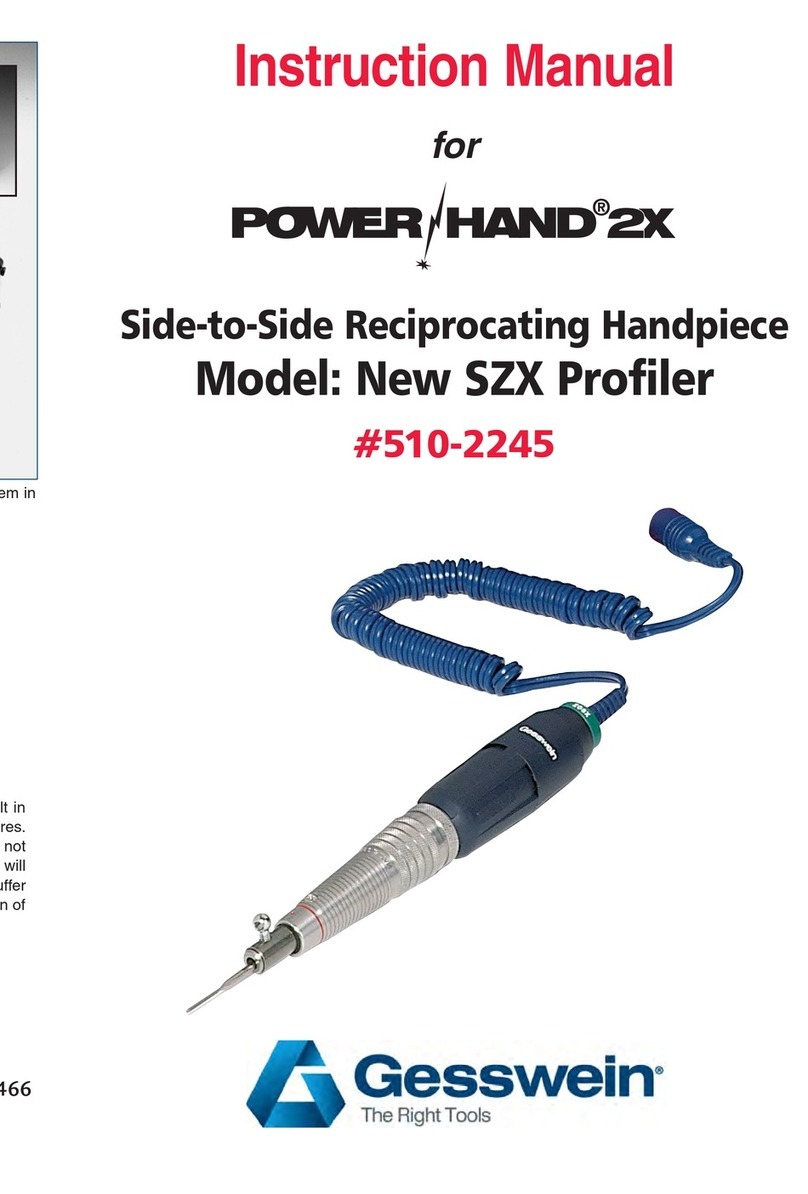
Gesswein ULTRAMAX DF POWER UF-0103 User manual

8914268/2211
Instruction Manual
ULTRAMAX DF
POWER
#500-1320
Complete 115V set 500-1320, shown above, consists of the Power Pack (Controller) UF-0103 (500-1319), the Ultrasonic Handpiece
UF-9705 (500-1321), and the DC (Mechanical) Handpiece PHP35 (510-5144) with 1/8” collet.

1
1. Specifications
Power Pack
Model No.
Ultramax DF Power UF-0103 (115V: 500-1319)
Input Power Voltage
Single-phase AC100~120V 50/60Hz
Fuse
Part No.:7556 / Rating:3.15A-250V / Size:5×20 / 2 pcs. are used.
Input Capacity
Ultrasonic :300VA / DC motor : DC30V 4A
Output Capacity
100W
Frequency adjustment
Automatic tracking system (Tracking range: 17 kHz – 31 kHz)
Output adjustment
Ultrasonic : Variable in 99 steps / DC motor : Variable in 99 steps
Protection function
FET temperature monitoring; overload detection; OSC Auto OFF, Frequency
detection, etc.
Operating temperature
range
0~40℃ (32°~104°F)
Operating humidity
range
30~80%RH (No condensing)
Outside dimensions
H215mm×W180mm×D252mm (without protrusion, rubber foot)
H8.5” X W7.1” X D9.9”
Weight
5.3kg
1.7lbs
215
180
252

2
Ultrasonic Handpieces
Model No.
UF-9705 (#500-1321)
Outside dimensions
Φ 28mm×L 128.5mm (without protrusion, rubber foot)
1 1/8” X L5.1”
Weight
150g (Cord is not included)
5.3 oz
Connection screw size
M6
M6
Air piping size
Φ4
Model No.
OPTIONAL HANDPIECE UF-7405 (#500-1322)
Cord
Φ 4.5mm×L 1.7m (Curl part abt.Φ16×L 50mm)
Outside dimensions
Φ 40mm×L 150mm (Without protrusion, rubber foot)
1 37/64 x L 5.9”
Weight
310g (Cord is not included)
10.9oz
Connection screw size
M8
Air piping size
Φ4
Φ28
Φ11.5
128.5
Φ40
Φ16
150

3
DC motor handpiece
Model No.
PHP35 (#510-5144 with 1/8” collet)
Maximum rotation speed
35,000 rpm / DC30V
Torque output
6.5N・cm
Cord length
1.5 m
59 Inches
Outside dimensions
Φ 16.0 mm × Φ 26.0 mm × L150.0 mm
(Diameter: 0.629” to 1” Length 6”)
Weight
200 g (Cord is not included)
7.1 oz

4
Optional Handpiece UF-7405 (500-1322)
Comes Complete with
- Transducer (Handpiece) UF-7405
- Standard tools & accessories

5
500-1320 Comes Complete with
- Oscillator (Controller) UF-0103
- Transducer (Handpiece) UF-9705
- DC motor (Handpiece) PHP35
- Standard tools & accessories
*-marked tools are attached to the handpiece UF-9705 at the time of delivery.
Standard tools supplied
Tool No,
Product name
Description
Q'ty
MS-0064*
Adaptor
Adaptor M6 to M4
I
SE-5845
Diamond file
Flat Square/ 0.8-0.3t x 4w #200 (M4)
I
SE-980 1
Diamond file
Cylinder/ 1.0 dia. #200 (M4)
I
SE-7841
Diamond file
Flat with angle/ 1.0t x 4w 45° #200 (M4)
1
SE-6803
Diamond file
Cone/ 3.0 dia. #200+ (M4)
1
SE-3803
Diamond file
Trigonal pyramid/ 3.0∆ #200 (M4)
1
SE-8851
Diamond file
Flat Square/ 1.0t x 5w x 124L #200 (M4)
1
MD-8862-C1
Diamond file
Flat Square/ 1.5t x 5w x 81L #200 (M4)
1
SD-4862
Diamond stone
Flat Square/ 1.5t x 6w #200 (M4)
1
SD-1802
Diamond stone
Cylinder/ 2.0 dia. #200 (M4)
1
NSP106F
Ceramic stone
Flat/ 1.0t x 6w x 40L #600
1
NSB106F
Ceramic stone
Flat/ 1.0t x 6w x 40L #800 Blue
1
NSPD3F
Ceramic stone
Round/ 3.0 dia. #600 Brown
1
NSBD3F
Ceramic stone
Round/ 3.0 dia. #800 Blue
1
MX-4010
Tool clomps
For 1.0t (M6)
1
MX-1030
Tool clomps
For 3.0 dia. (M6)
1
UF-7302
Wrench
Spanner Wrench M8
1
UF-7305
Wrench
Spanner Wrench M10
2
UF-7003
Clomp horn key
Clamp horn key M3 (Hexagonal wrench)
1
UF-7101
Power cord
(115V)
1
UF-7556
Replacement fuse
1OOV3.15AX2
1
UF-7024*
Protector sleeve
12/ 15 dia. X 30L
1
UF-7025
Protector sleeve
24 dia. X46L
1
UF-7 117
For plug
One Size Fits All
1
UF-7502
Hand-piece rest
Mode of rubber
1
UF-7022
Plastic Tool case
Plastic Tool case
1
UF-708q
Tool roll
Mode of cloth Blue
1

6

7
2.Table of Contents
1. Specifications ...........................................................................................................................................................................................1
1. Power Pack...................................................................................................................................................................................................................... 1
2. Ultrasonic handpiece ...................................................................................................................................................................................................... 2
3. DC motor handpiece ....................................................................................................................................................................................................... 3
4. Accessories…………………………………………………………………………………………………………………………………………………………….4-6
2. Table of Contents............................................................................................................................................................................................................. 7-9
3. Precautions ....................................................................................................................................................................................................................... 10
1. Warning......................................................................................................................................................................................................................... 10
2. Caution ..................................................................................................................................................................................................................... 11-12
4. Location and Description of Various Labels...............................................................................................................................................13
5. Name of each part and function................................................................................................................................................................14
1. Power Pack.................................................................................................................................................................................................................... 14
2. Transducer .................................................................................................................................................................................................................... 15
(1) Transducer body .................................................................................................................................................................................................... 15
(2) Installation of example of transducer tool ........................................................................................................................................................... 16
3. Transducer – Integrated tools...................................................................................................................................................................................... 17
4. Transducer – Tool Clamp ............................................................................................................................................................................................. 17
5. Transducer – Adaptor................................................................................................................................................................................................... 17
6. DC motor handpiece ..................................................................................................................................................................................................... 18
(1) DC motor handpiece body ..................................................................................................................................................................................... 18
(2) Installation example of the Tip tool for DC motor handpiece............................................................................................................................. 19
6. Installation/Connection ...........................................................................................................................................................................19
1. Installation of Power Pack ........................................................................................................................................................................................... 19
2. Power supply and grounding........................................................................................................................................................................................ 19
3. Connecting the Parts .................................................................................................................................................................................................... 20
(1) Transducer/DC motor handpiece.......................................................................................................................................................................... 20
(2) Foot Switch Receptacle ......................................................................................................................................................................................... 20
4. In case of using the cooling air..................................................................................................................................................................................... 21

8
(1) Caution for cooling air........................................................................................................................................................................................... 21
(2) Supply of cooling air .............................................................................................................................................................................................. 21
7. Cleaning and Detaching the Tools ............................................................................................................................................................22
1. Tools required ............................................................................................................................................................................................................... 22
2. Cleaning ........................................................................................................................................................................................................................ 22
(1) Cleaning points of parts........................................................................................................................................................................................ 22
(2) Cleaning method.................................................................................................................................................................................................... 23
3. Attaching / detaching the tools to / from corn ............................................................................................................................................................. 24
(1) How to put on and take off with only a wrench ................................................................................................................................................... 24
(2) How to attach Tool extractor ................................................................................................................................................................................ 25
(3) Detachment method using Tool extractor............................................................................................................................................................ 25
4. Attaching and detaching the clamped tools ................................................................................................................................................................ 26
5. Attaching and detaching Tip tools (or blank bar) for DC motor handpiece .............................................................................................................. 26
6. Replacement of the parts for DC motor handpiece .................................................................................................................................................... 27
(1) How to replace the Collet chuck ........................................................................................................................................................................... 27
(2) How to replace the Carbon brushes...................................................................................................................................................................... 27
8. Operating procedures....................................................................................................................................................................................................... 28
1. Basic operation (Common to Ultrasonic/DC motor handpiece).................................................................................................................................. 28
2. On Startup .................................................................................................................................................................................................................... 28
3. Operation button........................................................................................................................................................................................................... 29
9. Ultrasonic mode................................................................................................................................................................................................................ 30
1. Window description ...................................................................................................................................................................................................... 30
2. Characteristics of Ultrasonic Vibration and Tools...................................................................................................................................................... 31
(1) Tools to be attached to the equipment ................................................................................................................................................................ 31
(2) Basic principle and how to determine the tool shape............................................................................................................................................ 31
3. CLAMP mode ................................................................................................................................................................................................................ 32
4. FILING (Drive) mode ................................................................................................................................................................................................... 32
5. TOUCH function........................................................................................................................................................................................................... 33
6. NANO function ............................................................................................................................................................................................................. 33
7. FINE function ............................................................................................................................................................................................................... 34

9
10. DC motor mode................................................................................................................................................................................................................. 35
1. Window description ...................................................................................................................................................................................................... 35
2. Forward / Reverse......................................................................................................................................................................................................... 36
3. Variable Foot Controller............................................................................................................................................................................................... 36
4. Auto cruise .................................................................................................................................................................................................................... 37
11. MENU ............................................................................................................................................................................................................................... 38
1. Operating procedures ................................................................................................................................................................................................... 38
(1) Window display and Operation part .................................................................................................................................................................... 38
(2) List of operation items .......................................................................................................................................................................................... 38
2. US DRIVE MODE ........................................................................................................................................................................................................ 39
3. AUTO OFF .................................................................................................................................................................................................................... 39
4. LCD CONTROL............................................................................................................................................................................................................ 40
5. LAST ERROR ............................................................................................................................................................................................................... 40
6. VERSION ...................................................................................................................................................................................................................... 41
7. EXTBOARD VERSION ................................................................................................................................................................................................ 41
8. Reset settings................................................................................................................................................................................................................ 39
12. Error and Message..................................................................................................................................................................................43
1. Error .............................................................................................................................................................................................................................. 43
2. Message ......................................................................................................................................................................................................................... 43
13. Error Code ........................................................................................................................................................................................................................ 44
14. Troubleshooting................................................................................................................................................................................................................ 45
1. Check first ................................................................................................................................................................................................................ 45-46
2. What to do in these situations ..................................................................................................................................................................................... 46
(1) Power Pack temperature rise protection.............................................................................................................................................................. 47
(2) Display of Abnormal Frequency Icon (WARN) .................................................................................................................................................... 47
(3) Method for judging damage of tool and failure of transducer ........................................................................................................................... 47
15. Maintenance of Power Pack .....................................................................................................................................................................48
1. Replacement of Fuse..................................................................................................................................................................................................... 48
2. Cleaning of Fan filter ................................................................................................................................................................................................... 48
16. Product warranty ........................................................................................................................................................................................................ 49-50
10
3. Precautions
The following precautions must be observed as the minimum requirements for using the equipment safe.
Neglecting the safety precaution may result in a hazard that may result in death or serious personal injury, thereby
damaging the personal body or other properties.
Failures that are incurred by neglecting the following precautions result in the loss of the claim right for regular
warranty and repair. Be sure to refer to this Operating Instructions to ensure safe operation of the apparatus.
This symbol indicates the
presence of prohibited actions on
the apparatus.
This symbol indicates the
presence of a precaution for
handling the apparatus.
This symbol indicates the
presence of instructions that must
be observed when handling the
apparatus.
1. Warning
Do not disassemble or remodel the part that is not instructed by the Operating Instructions.
Do not use in areas with lacquer, paint, thinner, gasoline, gas, adhesives or other substances
that may catch fire or explode.
Do not touch the equipment with wet hands.
There is a risk of unexpected accidents such as electric shock and corrosion
Do not open or close the chuck opening / closing ring while the rotation of the DC motor
handpiece is ON.
Do not use the DC motor handpiece in a dangerous condition where cotton work gloves, rubber
gloves, clothing sleeves, hair, waste cloth, paper, etc. may get caught.
Do not touch the electrodes of the connector.
A high voltage may be charged at the electrodes of the oscillator-oscillator connector or the
electrodes of the power connector of the oscillator, resulting in electric shock hazard.
Do not touch the vibrating or rotating parts. If you touch a vibrating part such as a tool or horn
during oscillation, or a rotating tool or collet chuck, you may get burned due to frictional heat.
Also, please note that the tip of the transducer / DC motor handpiece may be hot even after use.

11
If you continue to use it for a long time, vibrations will be transmitted to your hands, which may
cause problems such as numbness in your hands. In addition, the transducer and DC motor
handpiece may generate heat, resulting in low-temperature burns.
Ground the equipment.
After checking the specifications of the power outlet, ensure that the equipment can be grounded
when the power plug is connected.
Use the protective goggles and the dust protective mask.
Abrasive grains, abrasive powder, fragments of broken tool, etc. may be scattered.
Use ear protective gears such as earplugs and earmuffs.
Abnormal sounds or ultrasonic sound pressure that affects the ear resulting in difficulty in
hearing, etc. may be generated, depending on tools used or machining conditions.
2. Caution
Do not use or install in such places where:
The equipment is exposed to direct sunlight or installed outside;
Water is splashed on the equipment or the equipment is wetted;
The equipment is exposed to corrosive gases or high humidity or there is a lot of dust;
The equipment is located near heat-generating sources such as open flame; and
Strong magnetic field is generated, such as high-voltage electrical power line, motor, and
transformer.
Do not drop the machine from a high place or subject it to vibration or shock. Not only may the
machine malfunction,
but the transducer and DC motor handpiece may damage other objects.
Do not pull the cables by force, bend them excessively, or damage them with tools or the like.
Setting and installing tools should be done robustly.
Ultrasonic vibrations utilize resonance of tools. Stable vibrations can only be obtained when the
tool mounted on the handpiece, adapter, clamp horn and tools are coupled in a manner that they
are almost integrated with the handpiece, without allowing looseness or clearances. Clean joint
surfaces of such devices and tighten them with the purpose-designed spanner robustly.
Insufficient tightening may result in malfunction or failure.
When not using the DC motor handpiece, attach a blank bar to the collet chuck and store it.
If it is left for a long time without the blank bar attached, the opening of the collet chuck will be
narrowed, which may shorten the tool service life.

12
When you start to use the DC motor handpiece first time just after you bought or when the carbon
brushes were replaced by new one, please rotate the DC motor handpiece with a blank bar for
about 30 minutes without any load. The rotation sound becomes stable, and warming up can be
done properly.
During the rotation of the DC motor handpiece, unexpected contact may cause the tip tool
installed into the handpiece to fly off.
Do not exceed the durable rotation speed (maximum rotation speed) specified by each tip tool.
Do not leave the ultrasonic oscillation or rotation turned on.
When idling, ensure safety and always be able to respond to prevent malfunctions.

13
4. Location and Description of Various Labels
1
Electric Shock Warning
Please note that you may get an electric shock if you touch the receptacle
directly.
2
Labels
The frequency, output capacity, power supply voltage, input capacity, and
serial number are listed.
3
CE mark & UKCA mark
This equipment complies with the following directives of Comite
Europeen de Normalisation and British Standards Institution
EMC Directive EN 61000-6-4:2007+A1:2001
BS EN 61000-6-4:2007+A1:2001
EN 61000-6-2:2005
BS EN 61000-6-2:2005
Low Voltage Directive EN 61010-1:2010 BS EN 61010-1:2010
4
MIC Designation
In case a facility using high frequencies is installed in Japan, it is
necessary to individually notify the approval for installation to the Ministry
of Internal Affairs and Communications (MIC). With this equipment,
however, it is not necessary to notify the individual “Installation Approval
of Facility Using High Frequencies” since the type designation is obtained
from the Minister of MIC. The term “facility using high frequencies” implies
the facility which generates high-frequency energy by utilizing high-
frequency current of 10 kHz or more and uses the high-frequency output
exceeding 50 W.
MIC Designation No. AK・・・・・・・
5
Fuse standard
The Fuse standard is described.
6
Power supply voltage
standard
The Power supply voltage standard is described.
4
5
3
2
1
6

14
5. Name of each part and function
1. Power Pack (#500-1319)
1
LCD Window
Various information such as Output value/ Load, Mode, and
Menu settings etc., are displayed.
2
OUTPUT button (OUTPUT)
When the OUTPUT button (2) is turned on, Power Pack or
rotation is turned on and the button lights up in yellow-green.
3
DIAL
Output setting value can be adjusted with DIAL.
4
POWER SWITCH (POWER)
Oscillator starts when the POWER SWITCH is turned on.
5
CLAMP HARD/SOFT button
(CLAMP HARD/SOFT)
In Ultrasonic mode, it can switch to ON or OFF in CLAMP
mode.
It can switch to HARD mode or SOFT mode in the FILING
(Drive) mode by pressing and holding.
6
Operation buttons
The item displayed on the LCD Window can be selected.
7
Transducer Connection Receptacle
The transducer can be connected.
8
DC Motor Connection Receptacle
The DC motor handpiece can be connected.
9
Collapsible Stand
This Collapsible Stand can be folded and adjust the height of
the machine.
10
Exhaust Port
It exhausts the heat of the power pack.
11
Air Intake Fan
The cooling air is supplied to the power pack through Air
Intake Fan.
12
Serial port
This is for the maintenance. It is not used usually.
13
Foot Switch Receptacle (FOOT)
Optional On/Off Foot switch or Variable Foot controller can
be connected. (sold separately)
14
Fuse Box
Two fuses are stored.
15
Power Supply Receptacle
Power cord can be connected.
1
2
4
3
5
7
8
10
13
14
11
12
15
6
9

15
2. Ultrasonic DF Power Handpieces
UF-9705 (#500-1321)
Optional UF-7405 (#500-1322)
1
Cord
It can be connected to the Power Pack.
2
Housing
It can be used as the handle.
3
Protector sleeve
It can be used as the handle. It is a screw type and can be attached and
detached.
Remove the Protector sleeve when replacing the tool.
4
Corn
A part of the transducer unit to which a tool can be attached. The Protective
sleeve must be removed.
Do not touch while vibrating. Friction can cause burns.
5
Wrench catcher
It is used to hook the Wrench when changing tools.
6
Air inlet
Air tube in diameter of 4mm can be connected. When air is run through the
inlet, the transducer is cooled and it flows out near the cone.
Use at an air flow rate of 50 L / m or less.
4
1
2
5
6
3
1
2
4
5
6

16
(1) Installation example of transducer tool
UF-9705
UF-7405
Depending on the applications, M4 to M8 tools can be replaced.
By using the 508-3342 Adapter (A), M4 tools and Tool cl am p c an be attached to M6 cones.
A
M4
M6
M8

17
3. Transducer - Integrated tools
This is the tool with an integrated file and connecting part. Output value can be used in the maximum level.
1
Diamond file
This is the tool with high grinding force that is electrodeposited with
diamond abrasive grains.
2
Diamond abrasive stone
(Metal bond)
This is the abrasive stone made by molding and sintering metal powder
or diamond particles. It has a long life because it can be used not only
on the surface but by internal part.
4. Transducer - Too l Clamp
It can be used by clamping the tip tools such as ceramic stones.
If the output setting value is increased too much, the tip tool may burn out. Please use in CLAMP mode.
1
Too l Clamp
The tool that cannot be installed alone can be installed.
The shape of the Tool clamp differs depending on the tip tool to be
installed.
2
Ceramic stone
(Clamped tool)
This is the tip tool that can be clamped and used.
Ceramic stone is a composite material of alumina fiber and
thermosetting resin. As it does not clog and does not break easily, it is
possible to finish fine surfaces and delicate portion.
5. Transducer - Adaptor
1
Adaptor
This converts the tool screw diameter from M6 to M4. (508-3342)
1
2
1
2
1

18
6. DC motor handpiece (#510-5144)
(1) DC motor handpiece body
PHP35
1
Motor Cord
It can be connected to the Power Pack.
2
Carbon Housing Cover
The Carbon Brushes are built in.
3
Motor Case
The Motor is built in.
4
Set Ring
The collet chuck (6) can be opened or closed by twisting left and right.
R : To remove (Tip tools can be removed)
S : To se cu r e (Tip to ol s c a n be se cu r ed )
5
Head
Head can be removed when changing the Collet chuck.
6
Collet chuck
Tip tools can be installed into the Collet chuck.
7
Blank bar
To p re ve n t d i s to r ti o n of t h e co ll e t chuck, always leave a tip tool or Blank bar
in the Collet Chuck.
(2) Installation example of the Tip tool for DC motor handpiece
Use a Tip tool that meets the diameter of the collet chuck. Collet chuck in diameter of 1/8” 3.3mm is installed as
standard in the 500-1320 complete set and in the replacement handpiece (our 510-5144)
When installing a rotary tool in diameter of 2.34 mm, refer to "How to replace the collet chuck (p.25)". Or use a
reducing collet such as our 816-1501 for a 1/8” to 3/32” reduction.
1
2
3
4
5
6
7

19
6. Installation / Connection
1. Installation of Power Pack
The front part of the oscillator can be lifted by raising the Collapsible Stand (A). Please use it if necessary.
Please check the following installation conditions in order to install safely.
l The front face should be seen and operated.
l There are no obstacles within 100mm (4”) from
the back face and ventilation is good
l The Exhaust port (B) and Intake fan (C) are not
blocked.
l Do not place it horizontally, avoid tilting it, and be
sure to install it on a flat surface.
l An environment with an operating temperature
range of 0 to 40°C (32° to 104°F) and a humidity
range of 30 to 80%.
l Do not allow condensation.
2. Power supply and grounding
After checking the “Power Supply Spec.” on the back of the oscillator, connect the “Power Cord” which comes with
the equipment to the “Power Receptacle.”
To pr e ve nt ac c id en t s, be s u re to apply grounding (earth/GND).
B
C
A
B
A
This manual suits for next models
1
Table of contents
Other Gesswein Power Tools manuals

Gesswein
Gesswein Z-ANX User manual

Gesswein
Gesswein Z-CNX User manual

Gesswein
Gesswein Powerhand 2X User manual

Gesswein
Gesswein POWER HAND 3 PH3 55X User manual

Gesswein
Gesswein UTR Series User manual

Gesswein
Gesswein PH3 15X User manual

Gesswein
Gesswein POWER HAND 2X Z-2X User manual

Gesswein
Gesswein POWER HAND 2X Z-6X User manual
Popular Power Tools manuals by other brands

HIKOKI
HIKOKI WM 14DBL Handling instructions

Makita
Makita BJR240 instruction manual

ABB
ABB GSec/T1 Instructions for installation, operation and maintenance

DeWalt
DeWalt DW980 instruction manual

Stanley
Stanley ProSert XTN20 instruction manual

Parkside
Parkside PSTDA 20-LI B3 Translation of the original instructions