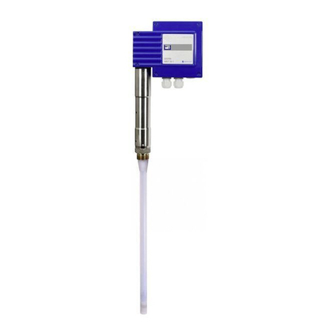
GESTRA LRG 16-9 Service manual

1
EN
English
Original Installation Instructions
818867-04
Conductivity Electrode
LRG 16-9

2
Contents
Page
Important notes
Usage for the intended purpose...............................................................................................................4
Function..................................................................................................................................................4
Important notes
Safety note..............................................................................................................................................5
Directives and standards
Pressure Equipment Directive 2014/68/EU..............................................................................................6
VdTÜV Bulletin "Water Monitoring 100"...................................................................................................6
Approvals for Marine Applications ...........................................................................................................6
ATEX (Atmosphère Explosible) .................................................................................................................6
UL/cUL (CSA) Approval ............................................................................................................................6
Note on the Declaration of Conformity / Declaration by the Manufacturer ..........................................6
Technical data
LRG 16-9 ................................................................................................................................................7
Scope of supply ......................................................................................................................................7
Name plate / marking.............................................................................................................................7
Installation
Dimensions LRG 16-9 .............................................................................................................................8
Mounting conductivity electrode..............................................................................................................9
Key .........................................................................................................................................................9
Tools.......................................................................................................................................................9

3
Contents
Page
- continued -
Dimensions and examples of installation
LRG 16-9 ..............................................................................................................................................10
LRG 16-9 ..............................................................................................................................................11
Key .......................................................................................................................................................11
LRG 16-9 ..............................................................................................................................................12
Key .......................................................................................................................................................12
Electrical connection
Connecting the conductivity electrode...................................................................................................13
Leitfähigkeitselektrode LRG 16-9, Belegung Stecker - Buchse ..............................................................13
Troubleshooting
Indication, diagnosis and remedy ..........................................................................................................14
Maintenance
Safety note............................................................................................................................................15
Cleaning measuring electrode...............................................................................................................15
Removing and disposing of the conductivity electrode
Remove and discard conductivity electrode LRG 16-9 ...........................................................................15

4
Important notes
Usage for the intended purpose
The conductivity electrode LRG 16-9 together with the conductivity switch LRS 1-.. or conductivity
controller LRR 1-.. is designed for measuring and monitoring electrical conductivity in conductive
fluids.
If used as conductivity limiter or continuous blowdown controller in steam boilers, the conductivity
electrode LRG 16-9 can be used with the following equipment:
Conductivity switch LRS 1-7
Conductivity switch LRS 1-50
Conductivity controller LRR 1-50
Conductivity controller LRR 1-52
To guarantee a trouble-free operation observe the requirements made on water as specified in the
pertinent TRD and EN regulations.
The equipment must only be used within the admissible pressure and temperature ratings.
Function
The conductivity electrode LRG 16-9 is used in combination with the following equipment as conductivity
limiter and continuous blowdown controller in steam boilers:
Conductivity switch LRS 1-7
Conductivity switch LRS 1-50
Conductivity controller LRR 1-50
Conductivity controller LRR 1-52
In addition the equipment can measure conductivity in condensate and feedwater systems and in cool-
ing and cleaning water.
The conductivity electrode LRG 16-9 in conjunction with conductivity switch LRS 1-7 is also approved
for feedwater monitoring on board of seagoing vessels.
The conductivity electrode works in conjunction with conductivity switches or controllers and monitors
the conductivity in conductive fluids.
To measure the fluid temperature a resistance thermometer Pt 100 is integrated in the electrode.
A short circuit or wire breakage in the conductivity electrode will trigger an error message in the con-
ductivity switch or controller.

5
Important notes
Attention
The name plate specifies the technical features of the equipment. Do not commission or
operate any item of equipment that does not bear its specific name plate.
Safety note
Danger
When loosening the conductivity electrode steam or hot water might escape!
This presents the risk of severe scalding all over the body!
It is therefore essential not to dismantle the electrode unless the boiler pressure is verified
to be 0 bar.
The conductivity electrode becomes hot during operation.
Risk of severe burns to hands and arms.
Before carrying out installation and maintenance work make sure that the equipment is
cold.
The equipment must only be installed, wired and commissioned by qualified and competent staff.
Retrofitting and maintenance work must only be performed by qualified staff who - through adequate
training - have achieved a recognised level of competence.
- continued -

6
Directives and standards
VdTÜV Bulletin "Water Monitoring 100"
The conductivity electrode LRG 16-9 in conjunction with the following conductivity switches and con-
trollers is type approved according to VdTÜV Bulletin "Water Level 100": LRS 1-7, LRS 1-50, LRR 1-50
and LRR 1-52.
The VdTÜV Bulletin "Water Monitoring 100" states the requirements made on water monitoring
equipment.
ATEX (Atmosphère Explosible)
The equipment is a simple item of electrical equipment according to DIN EN 50020 section 5.4. Ac-
cording to the European Directive 2014/34/EU the equipment must be equipped with approved Zener
barriers if used in potentially explosive areas. Applicable in Ex zones 1, 2 (1999/92/EC). The equipment
is not Ex marked.
UL/cUL (CSA) Approval
The equipment complies with the requirements of the following standards: UL 508 and CSA C22.2
No. 14-13, Standards for Industrial Control Equipment. File E243189.
Approvals for Marine Applications
The conductivity electrode LRG 16-9 in conjunction with conductivity switch LRS 1-7 is approved for
feedwater monitoring on seagoing vessels. See data sheet.
Pressure Equipment Directive 2014/68/EU
The conductivity control and monitoring equipment LRG 1.-.., LRS 1-.., LRR 1-5. meet the safety re-
quirements of the Pressure Equipment Directive (PED). The conductivity control & monitoring equipment
is EC type approved according to EN 12952/EN 12953. These Directives state, among other things, the
requirements made on limiting systems and equipment for steam boiler plants and (pressurised) hot-
water installations.
Note on the Declaration of Conformity / Declaration by the Manufacturer
For details on the conformity of our equipment according to the European Directives see our Declaration
of Conformity or our Declaration of Manufacturer.
The current Declaration of Conformity and Declaration of Manufacturer are available in the Internet under
www.gestra.com documents
or can be requested from us.
7
TÜV . WÜL . XX-014 / XX-017 / XX-018
32 bar 238°C T amb = 70°C
PN 40 G 1/2” 1.4571 IP 65
GESTRA AG · Münchener Straße 77 · D-28215 Bremen
LRG 16-9
Mat-Nr: xxxxxx
LRG 16-9
Service pressure
PN 40, 32 bar at 238°C
Mechanical connection
Screwed G ½ A, ISO 228 (NPT also available)
Materials
Screw-in body: 1.4571, X6CrNiMoTi17-12-2
Measuring electrode: 1.4571, X6CrNiMoTi17-12-2
Electrode rod insulation: PEEK
Cell constant
0.5 cm-1
Electrical connection
M 12 sensor connector, 5 poles, A coded
Protection
IP 65 to DIN EN 60529
Ambient temperature
Max. 70°C
Weight
Approx. 0.3 kg
Approvals:
TÜV certificate VdTÜV Bulletin "Wasserüberwachung 100" (= Water Monitoring 100):
Requirements made on water monitoring equipment
Type approval: TÜV · WÜL · XX-014, XX-017, XX-018 (see name plate)
UL/cUL (CSA) Approval UL 508 and CSA C22.2 No. 14-13, Standards for Industrial Control Equipment.
File E243189.
Marine applications In accordance with Germanischer Lloyd Directive GL 60444-09 HH
Technical data
Name plate / marking
LRG 16-9
1 Conductivity electrode LRG 16-9
1 Joint ring 21 x 26, form D, DIN 7603, 1.4301, bright annealed
1 Installation manual
Scope of supply
Fig. 1
Equipment designation
Manufacturer
Pressure rating, thread type,
material number, protection
Service pressure
& temperature,
admissible ambient temp.
Type approval no.

8
Installation
Dimensions LRG 16-9
∅26
Fig. 2 LRG 16-9
1
2
3
4
5
G ½ A, ISO 228
43
~ 187
Space required for servicing = 50 mm
Ra 3.2
0.5
∅ 27
G
½
A, ISO 228
Ra 12.5
Fig. 3
∅18
27

9
Key
1M 12 Sensor connector, 5 poles, A coded
2Electrode thread G ½ A, ISO 228
3Measuring tube
4Measuring surface
5Joint ring 21 x 26 form D to DIN 7603, made from 1.4301, bright annealed
Note
The conductivity electrode is designed for installation in pipes.
The conductivity electrode is installed in a socket end, a measuring chamber or a
mounting flange.
When installing the conductivity electrode please consider a min. space of 50 mm
required for servicing and removing the conductivity electrode.
Installation
Attention
Install conductivity electrode horizontally or with a vertical inclination. The measuring
surface must be permanently submerged.
Make sure that the sealing surface of the screwed connection is accurately machined.
Use only the supplied ring joint 21 x 26, form D, DIN 7603, made from 1.4301, bright
annealed!
Do not insulate electrode thread with hemp or PTFE tape!
Do not apply conductive paste or grease to the electrode thread!
Observe the specified tightening torque.
Leave a space of approx. 15 mm between the lower end of the measuring tube and
the wall of the pipe.
Do not cut the measuring electrode and the measuring tube!
Mounting conductivity electrode
1. Check seating surfaces. Fig. 3
2. Place supplied joint ring 3onto seating surface of the threaded standpipe or flange.
3. Apply a light smear of heat resistant silicone grease (e. g. WINIX® 2150) to the electrode thread 3.
4. Screw conductivity electrode into threaded standpipe and tighten with an open-end spanner
A. F. 27 mm. The torque required for tightening when cold is 110 Nm.
Tools
Open-end spanner 27 mm A. F.
- continued -

10
2 bar 238°C T amb
PN 40 G 1/2”
ESTRA AGG ·
TÜV.WÜL.09-014/12-01
Münchener
LRG 16-9
2 bar 238°C T amb
PN 40 G 1/2”
ESTRA AGG ·
TÜV.WÜL.09-014/12-01
Münchener
LRG 16-9
Fig. 5
Conductivity electrode LRG 16-9 with measuring chamber for installation in pipes.
a
Dimensions and examples of installation
LRG 16-9
Fig. 6
Conductivity electrode LRG 16-9 with mounting flange for
sandwiching between flanges.
DN Flange
diameter
D
Thickness
of flange
15 95 32
20 105 32
25 115 32
40 150 32
D
Fig. 4
Conductivity electrode LRG 16-9 with on-site
socket end for installation in pipes.
6 7
R
R * = 15 mm
16
8
2 bar 238°C T amb
PN 40 G 1/2”
ESTRA AGG ·
TÜV.WÜL.09-014/12-01
Münchener
LRG 16-9
GESTRA
G1/2 PN40
1.4301
Made in Germany
9
0
70
48
t = 30
60
8
7
8
7

11
Key
6Socket end to EN 10241, heavy design, screwed
G½ A to ISO 228, length 16 mm, provided on site
7Conductivity electrode LRG 16-9
8Female connector (not supplied)
9Measuring chamber, G½, PN 40, made from 1.4301
0Drain plug
aMounting flange PN 40, DIN EN 1092-01
with female thread G½
bNon-return valve
cBall valve G½
dBall valve G3/8
Dimensions and examples of installation - continued -
LRG 16-9
Important Notes
The conductivity electrode is mounted in a bypass below the main line. This arrange-
ment prevents gas bubbles and flash steam from reaching the equipment. Fig. 7
A throttling point, e. g. a non-return valve (GESTRA type RK 86) should be installed in the
main line.
To prevent air and dirt particles from getting into the bypass make sure that the bypass
is below the main line.
2bar 238°C T amb
PN40 G1/2”
ESTRAAGG ·
TÜV.WÜL.09-014/12-01
Münchener
LRG16-9
GESTRA
G1/2 PN40
1.430 1
MadeinGermany
GESTRA
LRS1-7
Fig. 7
Conductivity electrode LRG 16-9 with measuring chamber for installation in a bypass
LRS 1-7
7
b
cc
d
9

12
Key
7Conductivity electrode LRG 16-9
9Measuring chamber, G ½, PN 40, 1.4301
bNon-return valve
cBall valve G ½
dBall valve G 3/8
eMeasuring sensor ORG 12 / 22
fResistance thermometer Pt 100
gMeasuring electrode
Dimensions and examples of installation - continued -
LRG 16-9
Important Notes
The conductivity electrode together with the measuring transducer ORGG 12 / 22 is
mounted in a bypass below the main line. This arrangement prevents gas bubbles and
flash steam from reaching the equipment. Please see also installation instructions for
OR 52-5 / OR 52-6. Fig. 8
A throttling point, e. g. a non-return valve (GESTRA type RK 86) should be installed in the
main line.
To prevent air and dirt particles from getting into the bypass make sure that the bypass
is below the main line.
ALARM
12
ppm
sec
cal
0
Test
PE
OIL
2bar 238°C Tamb
PN40 G1/2”
ESTRAAGG ·
TÜV.WÜL.09-014/12-01
Münchener
LRG 16-9
GESTRA
G1/2 PN40
1.4301
MadeinGermany
GESTRA
LRS1-7
Conductivity electrode LRG 16-9 with measuring chamber for installation in a bypass together
with the measuring sensor ORG 12 / 22 of the oil & turbidity detector OR 52-5 / OR 52-6.
LRS 1-7
7
b
d
c
e
9
d
d
ORT 6

13
51243
1
4
5
3
2
Electrical connection
The conductivity electrode LRG 16-9 is equipped with a sensor plug-in connection type M 12, with
5 poles, A-coded, pin assignment see Fig. 9. For connecting the electrode preconfigured control cable
assemblies (with male and female connectors) of various lengths are available as add-on equipment.
Note that the recommended control cable is not UV resistant and, if installed outdoors, must be
protected by a UV resistant plastic tube or cable duct.
If you do not use the prefabricated control cable assembly, use screened five-core control cable, e. g.
LiYCY 5 x 0.5 mm², for connecting the equipment. In addition, connect at the electrode end a screened
female connector to the control cable.
Max. cable length between conductivity electrode and switch or controller: 30 m, with
conductivities from 1 to 10 μS/cm: max. 10 m.
Attention
If the above-mentioned control cable assembly is not used, the connecting line must
be provided with a screened female connector according to the wiring diagram. Fig. 7.
Observe the mounting instructions of the connector manufacturer.
Make sure that connecting cables leading to the equipment are segregated and run
separately from power cables.
Connect screens according to the installation instructions for the conductivity switch-
es/controllers LRS 1-7, LRS 1-50, LRR 1-50 and LRR 1-52.
Connecting the conductivity electrode
Conductivity electrode LRG 16-9, pin assignment
Fig. 9
Connector/
Socket
Assignment Colour of
individual
conductors
1 Measuring electrode brown (BN)
2
Resistance thermometer
Pt 100
white (WH)
3 blue (BU)
4 black (BK)
5 Earth grey (GY)
Control cable
Female
connector
f
g
Conductivity electrode
Sensor plug-in connection

14
Attention
Before carrying out the fault diagnosis please check:
Supply voltage:
Is the conductivity switch / controller supplied with the mains voltage specified on the name
plate?
Wiring:
Is the wiring in accordance with the wiring diagram?
Troubleshooting
Indication, diagnosis and remedy
Conductivity switch / controller does not work
Error Remedy
Power failure. Switch on supply voltage. Check all electrical connections.
The earth connection to the vessel is interrupted.
Clean seating surfaces and screw in the conductivity
transmitter together with the joint ring 21 x 26, form D, DIN
7603 (made from 1.4301), bright annealed. Do not insulate
the electrode with hemp or PTFE tape!
Conductivity electrode defective, measured value too
low. Electrode lines interrupted or measuring surface
exposed.
Check connection of electrode lines. If necessary, replace
equipment. Check water level and installation.
Conductivity electrode defective, measured value too
high. Short circuit in electrode lines.
Check connection of electrode lines. If necessary, replace
equipment.
Temperature sensor defective, temperature reading
too low. Check conductivity electrode LRG 16-9 and, if necessary,
replace it with a new one. Check wiring (short circuit,
interruption?)
Temperature sensor defective, temperature reading
too high.
Indication of malfunctions
Conductivity switch / controller does not work accurately.
Error Remedy
Indicated conductivity reading is larger than the
measured reference value.
Increase temperature coefficient tC during commissioning.
Reduce correction factor CF during operation.
Indicated conductivity reading is smaller than the
measured reference value.
Reduce temperature coefficient tC during commissioning.
Increase correction factor CF during operation.
Measuring result cannot be adjusted by changing the
correction factor.
Remove conductivity electrode and clean measuring
surface.
Attention
For commissioning and troubleshooting also observe the installation & operating
manuals for LRS 1-7, LRS 1-50, LRR 1-50 and LRR 1-52.

15
If faults occur that are not listed above or cannot be corrected, please contact our service centre or
authorized agency in your country.
Cleaning measuring electrode
1. Detach sensor sleeve from the conductivity electrode.
2. Before removing the equipment make sure that is is neither hot nor under pressure.
Cleaning the measuring electrode (measuring surface):
Wipe off non-adhesive deposits with a grease-free cloth.
To remove adhesive deposits use emery cloth (medium grain).
Re-install the conductivity electrode. Observe the notes given in section "Installation" and "Electrical
Connection".
Maintenance
Safety note
Danger
When loosening the conductivity electrode steam or hot water might escape!
This presents the risk of severe scalding all over the body!
It is therefore essential not to dismantle the conductivity electrode unless the boiler
pressure is verified to be 0 bar.
The conductivity electrode becomes hot during operation.
Risk of severe burns to hands and arms.
Before carrying out installation and maintenance work make sure that the equipment is
cold.
The equipment must only be installed, wired and commissioned by qualified and competent staff.
Retrofitting and maintenance work must only be performed by qualified staff who - through adequate
training - have achieved a recognised level of competence.
1. Detach sensor sleeve from the conductivity electrode.
2. Before removing the equipment make sure that is is neither hot nor under pressure.
For the disposal of the equipment observe the pertinent legal regulations concerning waste disposal.
Removing and disposing of the conductivity electrode
Remove and discard conductivity electrode LRG 16-9

16
818867-04/06-2017cm (808786-04)
·
GESTRA AG
·
Bremen
·
Printed in Germany
GESTRA AG
Münchener Straße 77
28215 Bremen
Germany
Telefon +49 421 3503-0
Telefax +49 421 3503-393
E-mail [email protected]
Web www.gestra.de
Agencies all over the world: www.gestra.de
Table of contents
Other GESTRA Accessories manuals

GESTRA
GESTRA NRG 10-52 User manual

GESTRA
GESTRA LRG 16-60 Installation instructions

GESTRA
GESTRA NRG 26-60 User manual

GESTRA
GESTRA NRG 16-11 User manual

GESTRA
GESTRA NRG 26-61 User manual

GESTRA
GESTRA NRG 16-60 Installation instructions

GESTRA
GESTRA NRG 16-50S User manual

GESTRA
GESTRA NRG 16-36 User manual

GESTRA
GESTRA NRGT 26-1S Service manual
Popular Accessories manuals by other brands

Fiamma
Fiamma F35 Pro Series Installation and use instructions

Anker
Anker A1211 quick start guide

Sunx
Sunx MQ-W3 Specification sheet

Wenglor
Wenglor weCat3D MLWL Series operating instructions

Mitsubishi Electric
Mitsubishi Electric PAC-AK53BC installation manual

Summit Treestands
Summit Treestands Hex SU82097 manual