GESTRA NRG 16-11 User manual

1
Installation Instructions 818578-05
Level Electrode
NRG 16-11, NRG 17-11, NRG 19-11,
NRG 111-11
GESTRA Steam Systems
NRG 16-11
NRG 17-11
NRG 19-11
NRG 111-11
EN
English

2
Contents
Usage for the intended purpose ..............................................................................................................4
Safety note .............................................................................................................................................4
Danger ...................................................................................................................................................4
Attention.................................................................................................................................................4
PED (Pressure Equipment Directive)........................................................................................................4
ATEX (Atmosphère Explosible).................................................................................................................4
Important Notes
Page
Explanatory Notes
Scope of supply......................................................................................................................................5
Description NRG 16-11, NRG 17-11, NRG 19-11, NRG 111-11................................................................5
Function .................................................................................................................................................6
System components ...............................................................................................................................6
Design....................................................................................................................................................6
NRG 16-11, NRG 17-11, NRG 19-11, NRG 111-11, step 1.....................................................................17
NRG 16-11, NRG 17-11, NRG 19-11, NRG 111-11, step 2.....................................................................17
Attention...............................................................................................................................................17
Important notes ....................................................................................................................................18
Tools.....................................................................................................................................................18
Installation
NRG 16-11, NRG 17-11, NRG 19-11 .......................................................................................................7
NRG 111-11 ...........................................................................................................................................8
Name plate / marking .............................................................................................................................9
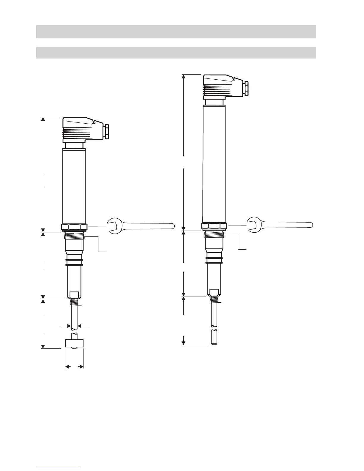
Dimensions NRG 16-11, NRG 17-11, NRG 19-11 ............................................................................ 10, 11
Dimensions NRG 111-11 ......................................................................................................................12
Technical Data
NRG 16-11, NRG 17-11, NRG 19-11, NRG 111-11 ................................................................................13
Key.......................................................................................................................................................16
Design
NRG 16-11, NRG 17-11, NRG 19-11 .....................................................................................................14
NRG 111-11, optional for NRG 16-11, NRG 17-11, NRG 19-11..............................................................15
Key.......................................................................................................................................................16
Functional Elements

3
Electrical Connection
NRG 16-11, NRG 17-11, NRG 19-11 .....................................................................................................22
NRG 111-11, optional for NRG 16-11, NRG 17-11, NRG 19-11..............................................................22
Wiring diagram.....................................................................................................................................23
Voltage table.........................................................................................................................................24
Note .....................................................................................................................................................24
Tools.....................................................................................................................................................24
Check wiring ........................................................................................................................................24
Apply mains voltage..............................................................................................................................24
Contents – continued –
Commissioning
Page
Note on the Declaration of Conformity / Declaration by the Manufacturer CE.........................................26
Annex
Low-level limiter...................................................................................................................................25
Note .....................................................................................................................................................25
Operation
Fault-finding list for troubleshooting......................................................................................................25
Operational Malfunctions
Danger .................................................................................................................................................26
Disposal................................................................................................................................................26
Decommissioning
NRG 16-11, NRG 17-11, NRG 19-11 .....................................................................................................19
NRG 111-11 .........................................................................................................................................20
Key.......................................................................................................................................................21
Examples of Installation

4
Important Notes
Danger
When loosening the electrode steam or hot water might escape.
This presents the danger of severe scalds to the whole body.
It is essential not to mount or dismantle the electrode unless the boiler pressure is
verified to be 0 bar.
The electrode becomes hot during operation.
Touching the hot equipment presents the risk of severe burns to hands and arms.
All installation and maintenance work must only be performed when the equipment is
cold.
If the internal ceramic insulation of the level electrode NRG 111-11 breaks hot steam
may escape through the lateral relief vent of the electrode stem.
This presents the danger of severe scalding!
Do not stand close to the electrode during operation.
Usage for the intended purpose
Use level electrodes NRG 16-11, NRG 17-11, NRG 19-11 and NRG 111-11 only in conjunction with
level switch NRS 1-7 for low-level limiting (low level alarm). The equipment must not be used in
explosion risk areas.
PED (Pressure Equipment Directive)
Safety note
The equipment must only be installed and commissioned by qualified and competent staff.
Retrofitting and maintenance work must only be performed by qualified staff – who through adequate
training – have achieved a recognised level of competence.
ATEX (Atmosphère Explosible)
The equipment constitutes a simple item of electrical equipment as defined in DIN EN 50020 section
5.4. According to the European Directive ATEX 94/9/EC the equipment may only be used in potentially
explosive atmospheres if it is provided with approved Zener barriers.
Applicable in Ex zones 1, 2 (1999/92/EC). The equipment does not bear an Ex marking. The suitability
of the Zener barriers is certified in a separate document.
The equipment fulfills the requirements of the PED 97/23/EC. The equipment can be used with fluids of
group 1 and 2. With CE marking (except for equipment according to section 3.3 of the PED).
Attention
The name plate specifies the technical features of the equipment. Note that any piece of
equipment without its specific name plate must neither be commissioned nor operated.

5
Explanatory Notes
Scope of supply
NRG 16-11
1 Level electrode NRG 16-11, PN 40
1 Joint ring 27 x 32, form D, DIN 7603, 1.4301, bright-annealed
1 Disk with set screw (measuring surface extension) – optional
1 Retaining ring – optional
1 Installation manual
NRG 17-11
1 Level electrode NRG 17-11, PN 63
1 Joint ring 27 x 32, form D, DIN 7603, 1.4301, bright-annealed
1 Disk with set screw (measuring surface extension) – optional
1 Retaining ring – optional
1 Installation manual
NRG 19-11
1 Level electrode NRG 19-11, PN 160
1 Joint ring 27 x 32, form D, DIN 7603, 1.4301, bright-annealed
1 Disk with set screw (measuring surface extension) – optional
1 Retaining ring – optional
1 Installation manual
NRG 111-11
1 Level electrode NRG 111-11, PN 320
1 Gasket 33 x 39 DIN 7603-1.4301
1 Sealing plug for M 20 connection
1 Surface extension disk with grub screw
1 Retaining ring
1 Installation manual
Description NRG 16-11, NRG 17-11, NRG 19-11, NRG 111-11
The level electrode NRG 1...-11 detects the min. liquid level (low level alarm) in a steam boiler.
The operation of the electrode is based on the conductivity measuring principle using the electrical
conductivity of water for signaling one liquid level:
n Low level alarm
The NRG 1...-11 is designed for use in conjunction with level switch NRS 1-7 as a self-monitoring low
level limiter with periodic self-checking (SMART) feature.
Application in steam and pressurised hot-water plants in accordance with TRD 604, sheet 1 and
sheet 2 (24 h/72 h operation) as well as DIN EN 12952 and DIN EN 12953.
The electrical equipment meets the requirements of the Regulations on Protection Circuits EN 50156-1.

6
Explanatory Notes – continued –
Function
The water level limiter comprises a level electrode type NRG 1...-11 and a level switch type NRS 1-7.
The level electrode NRG 1...-11 consists of two concentrically arranged electrodes (measuring elec-
trode and compensating electrode) which are isolated from each other by special insulating seals.
The level limiter operation is based on the conductive measuring principle using the electrical
conductivity of water for signaling water level. During normal, trouble-free operation the level electrode
tip is immersed in boiler water and no low level alarm is given. A low level alarm will only be raised if
the electrode tip is exposed for more than 3 seconds. A low level alarm will also be activated if the
insulating seals placed between the electrodes and the body are no longer pressure tight, allowing
water to penetrate into the body. However in this instance the alarm is caused by a malfunction of the
electrode, and confirmation should always be done by checking if there is water in the gauge glass.
The equipment combination NRG 1...-11 and NRG 1-7 provides fail safe protection against a first fault
in accordance with TRD 604.
System components
NRS 1-7
Level switch NRS 1-7. Two channel level limiter (redundancy) with periodic self-checking routine to
EN 50156-1.
Design
NRG 16-11, NRG 17-11, NRG 19-11
Screwed ¾" BSP, DIN EN ISO 228-1
Electrical connection: Four pole connector, terminal box made from aluminium (optional)
NRG 111-11
Screwed 1" BSP, DIN EN ISO 228-1
Electrical connection: Terminal box made from aluminium

7
NRG 16-11, NRG 17-11, NRG 19-11
Technical Data
Type approval
TÜV· WB·05-354
EG 01 202 931-B-01-0077
Service pressure
NRG 16-11: 32 bar at 238 °C
NRG 17-11: 60 bar at 275 °C
NRG 19-11: 100 bar at 311 °C
Connection
Screwed G ¾ A, to ISO 228
Materials
Screw-in body: 1.4571, X6CrNiMoTi17-12-2
Measuring electrode: 1.4571, X6CrNiMoTi17-12-2
Electrode rod: 1.4401, X5CrNiMo17-12-2
Electrode insulation: Gylon®
Four pole connector: Polyamid (PA)
Terminal box: 3.2161 G AISi8Cu3 (optional)
Lengths available
500 mm, 1000 mm, 1500 mm, 2000 mm, 2500 mm, 3000 mm
Cell constant C
0.13 cm-1 with measuring surface extension
0.3 cm-1 without measuring surface extension
Response sensitivity
10 µS/cm at 25 °C, cell constant 0.3 cm-1
0.5 µS/cm at 25 °C, cell constant 0.13 cm-1
Electrical connection
Four-pole connector, cable gland M 16,
terminal box made from aluminium, cable glands M 16 (optional)
Protection
IP 65 to EN 60529
Max. admissible ambient temperature
70 °C
Weight
Approx. 1.1 kg
Gylon®is a registered trademark of Garlock Sealing Technologies, Palmyra NY, USA

8
NRG 111-11
Type approval
TÜV· WB·05-354
EG 01 202 931-B-01-0077-01
Service pressure
NRG 111-11: 180 barg (at 357 °C)
Connection
1" BSP (to DIN EN ISO 228-1)
Materials
Screw-in body: 1.4529, X1NiCrMoCuN25-20-7
Measuring electrode 1.4122, X39CrMo17-1
Electrode rod: 1.4401, X5CrNiMo17-12-2
Electrode insulation: Special ceramic material
Terminal box: 3.2161 G AISi8Cu3
Lengths available
500 mm, 1000 mm, 1500 mm, 2000 mm, 2500 mm, 3000 mm
pH value
Max. admissible: 10
Cell constant C
0.13 cm-1 with measuring surface extension
Response sensitivity
0.5 μS/cm up to 400 μS/cm at 25 °C
Electrical connection
Terminal box made from aluminium, cable glands M 20 (2)
Protection
IP 65 to EN 60529
Max. admissible ambient temperature
70 °C
Weight
Approx. 1.8 kg
Technical Data – continued –

9
Technical Data – continued –
Name plate / marking
Equipment designation
Fig. 1
Fig. 2
Pmax
Tmax
MIN
PN 40 G 1.4571 IP 65
/
3
4
GESTRA AG Münchener Straße 77 D-28215 Bremen
-1
C=0,13 cm
TÜV .WB.05-354
32 bar (464psi)
238°C (460°F)
Tamb=70°C (158 °F)
NRG 16-11
0525
Betriebsanleitung beachten
See installation instructions
Voir instructions de montage
PmaxPmax
TmaxTmax 60 bar (870psi)
275°C (527°F)
32 bar (464psi)
238°C (460°F)
100 bar (1450psi)
311°C (592°F)
C=0,13 cm
C=0,3 cm
-1
-1
Betriebsanleitung
beachten
See installationinstructions
Voir instructions de
montage
PN 63
PN160
PN 40
NRG 17-11
NRG 19-11
NRG 16-11
G 3/4 1.4571 IP65
Tmax=70°C (158°F)
0525
GESTRA AG
Münchener Str.77
D-28215 Bremen
TÜV .WB.05-354
Fig. 3
Tamb = 70°C (158 °F)
Pmax
Tmax
NRG 111 - 11
G 1 1.4529 IP65
180 bar (2611psi)
357°C (675°F)
0525
mit Meßflächenvergrößerung
with measuring surface extention
agrandissement de la surface
de mesure
C (cm ) 0,13
-1 C (cm ) 0,3
-1
TÜV .WB . 05-354
GESTRA AG
Münchener Str.77
D-28215 Bremen
Betriebsanleitung
beachten.
See installation instructions.
Voir instructions de
montage.

10
Technical Data – continued –
Dimensions NRG 16-11, NRG 17-11, NRG 19-11
Fig. 5
NRG 17-11, NRG 19-11 without
measuring surface extension
≤1500 85 272
Fig. 4
NRG 16-11 with
measuring surface extension
8
≤1500
23
165
85
¾" BSP, DIN EN ISO 228-1
36
36

11
Technical Data – continued –
Dimensions NRG 16-11, NRG 17-11, NRG 19-11 – continued –
Fig. 6
NRG 17-11, NRG 19-11 with terminal box made from aluminium (optional)
and measuring surface extension
GESTRA SteamSystems
GESTRA
¾" BSP, DIN EN ISO 228-1
85 337.5
≥185
b = 70
140
175
≤1500
36

12
Technical Data – continued –
Dimensions NRG 111-11
GESTRA SteamSystems
GESTRA
Fig. 7
NRG 111-11 with measuring surface extension
≥185
500, 1000, 1500,
2000, 2500, 3000
b = 70
1" BSP, DIN EN ISO 228-1
30
85 337.5
140
175

13
Design
Fig. 11
NRG 16-11, NRG 17-11, NRG 19-11, NRG 111-11
Fig. 9
110
30
∅75
14
Fig. 8
Fig. 10
1
5
7
2
3
4
6
9
8
0
a
Fig. 12
RA 3,2
RA 12,5
G¾A, ISO 228
G1A, ISO 228
∅33
0,5

14
Functional Elements
NRG 16-11, NRG 17-11, NRG 19-11
Fig. 13
i
h
f
e
b
c
d
g

15
Functional Elements – continued –
NRG 111-11, optional for NRG 16-11, NRG 17-11, NRG 19-11
Fig. 15
GESTRA SteamS ystems
GESTRA
Fig. 14
j k l k
m
no

16
1Measuring electrode
2Bore
3Spring
4Electrode tip
5Grub screw
6Disk (Measuring surface extension)
7Retaining ring
8Gasket 27 x 32, form D, DIN 7603, 1.4301 bright annealed
9Seating surface
0Electrode thread
aThermal insulation, provided on site, d = 20 mm
(outside of thermal insulation of steam generating unit)
bScrew M 4
cLid
dUpper part of terminal box
eConnecting plate
fSealing element
gContact plate for level electrode
hCable clamp
iCable gland M 16 (PG 9)
jHousing screws M 4
kCable entry M 20 x 1.5
lHousing lid
mNut
nPE connection
oTerminal strip
Design / Functional Elements – continued –
Key

17
Attention
nThe seating surfaces and threads on the vessel and mounting flange must be
accurately machined, Fig. 12
nDo not bend the electrode tip when cutting.
nUse only the supplied gasket:
NRG 16-11, NRG 17-11, NRG 19-11: 27 x 32, form D, DIN 7603, 1.4301
NRG 111-11: D 33 x 39, DIN 7603-1.4301
nDo not lag the electrode body.
nDo not insulate the threads with hemp or PTFE tape.
nDo not apply conductive paste or grease to the electrode thread.
nProvide a min. spacing of 14 mm between electrode and earth (flange, boiler wall),
Fig. 11, Fig. 17
nObserve the minimum distances for the installation of the electrode.
nIf the level electrode NRG 111-11 is to be installed in a flanged standpipe DN 50 use
only the GESTRA hat flange! Fig. 11
nWhen using the level electrode NRG 111-11 take the pH limit value (10) and the max.
admissible electrical conductivity (100 µS/cm at 25 °C) into consideration.
Installation
NRG 16-11, NRG 17-11, NRG 19-11, NRG 111-11, step 1
1. Screw electrode tip 4into measuring electrode 1, Fig. 8
2. Carefully determine required measuring length, taking minimum length into account.
3. Mark length of electrode tip 4.
4. Unscrew electrode tip 4from measuring electrode 1and cut tip.
5. Screw electrode tip 4into measuring electrode 1and tighten. Slide spring 3along electrode tip
4, so that its bent end completely enters into small bore 2.
6. If a measuring surface extension is required slip disk 6onto electrode tip 4ensuring that the
electrode tip protrudes 2 mm from disk. Fasten disk with grub screw 5. Push retaining ring 7over
electrode tip against disk 6.
NRG 16-11, NRG 17-11, NRG 19-11, NRG 111-11, step 2
1. Check seating surfaces, Fig. 12
2. Place supplied gasket 8onto seating surface of the threaded standpipe or flange. Fig. 10
3. Apply a light smear of silicone grease (e. g. WINIX®2150) to electrode thread 0.
4. Screw level electrode into threads of flange provided on vessel and tighten with a 36/41 mm ring
spanner. The torque required is 160 Nm when cold (NRG 16-11, NRG 17-11, NRG 19-11) or
475 Nm (NRG 111-11).
WINIX®2150 is a registered trademark of WINIX GmbH, Norderstedt, Germany

18
Important notes
nOne level electrode NRG 1...-11 can be installed together with one GESTRA level
electrode, one level switch or transmitter for water level control and high level alarm
in one single protection tube or level pot (inside diameter 100 mm). Fig. 16. If the
NRG 1...-11 is installed inside the vessel, it must be at least 40 mm away from the
upper vent hole.
nThe installation of two level-limiting electrodes NRG 1...-11 in one standpipe is not
allowed!
nFor the approval of the boiler standpipe observe the relevant regulations.
nFor typical installation examples refer to pages 19 – 20.
nWhen mounting the electrode laterally make sure that the inclination angle does not
exceed 45° and that the length of the electrode rod is limited to 1000 mm. Fig. 17
nIf the electrode is installed outdoor, it must be provided with a weather-proof cover
supplied by GESTRA. As an alternative the level electrode can be equipped with a
terminal box made from aluminium.
Tools
nOpen-end spanner A. F. 13, DIN 3110, ISO 3318
nOpen-end spanner A. F. 36, DIN 3110, ISO 3318
nOpen-end spanner A. F. 41, DIN 3110, ISO 3318
nScriber
nHacksaw
nFlat file, cut 2, DIN 7261, form A
Installation – continued –

19
Examples of Installation
NRG 16-11, NRG 17-11, NRG 19-11
DN 100
Fig. 18
∅20
20
≥DN 20
24.5 24.5
20
∅20
Fig. 16
Fig. 19
DN 50
¾" BSP
¾" BSP
¾" BSP
≤20
≤3000
∅20
≤90°
∅20
¾" BSP
≤90°
Fig. 17
≥14
≥DN 20
≥DN 20
p
q
r
s
t
max. 1000
20
≥14
≥14
45°
p
q
t
s
rs
p
s
t
≥10
w
u
x
y
x
v
w
x
y
Centre distance

20
Examples of Installation – continued –
NRG 111-11
Centre distance
Fig. 20 Fig. 21
p
q
r
t
s
∅20
20
DN 50
1" BSP
∅20
≤90°
≥10
u
x
y
w
≥DN 20
Fig. 22
1" BSP
≤20
≥DN 20
≥DN 20
p
s
t
≥10 x
≥14
max. 1000
20
≥14
≥14
45°
This manual suits for next models
3
Table of contents
Other GESTRA Accessories manuals

GESTRA
GESTRA NRG 10-52 User manual

GESTRA
GESTRA NRG 16-60 Installation instructions

GESTRA
GESTRA NRG 16-36 User manual

GESTRA
GESTRA LRG 16-60 Installation instructions

GESTRA
GESTRA NRG 26-61 User manual

GESTRA
GESTRA NRGT 26-1S Service manual

GESTRA
GESTRA NRG 16-50S User manual

GESTRA
GESTRA NRG 26-60 User manual

GESTRA
GESTRA LRG 16-9 Service manual