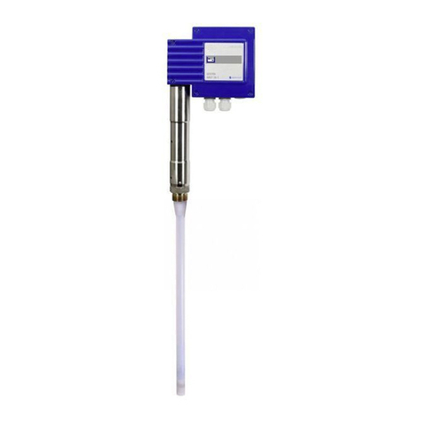
GESTRA NRG 16-60 Installation instructions

Original Installation &
Operating Manual
EN
English
Level Electrodes
NRG 16-60
NRG 17-60
NRG 19-60
NRG 111-60
819681-00

2NRG 1x-60 - Installation & Operating Manual - 819681-00
Contents
Content of this Manual....................................................................................................................................4
Scope of delivery/Product package................................................................................................................4
How to use this Manual...................................................................................................................................5
Illustrations and symbols used.......................................................................................................................5
Hazard symbols in this Manual.......................................................................................................................5
Types of warning .............................................................................................................................................6
Specialist terms/Abbreviations.......................................................................................................................7
Usage for the intended purpose...................................................................................................................... 8
Applicable directives and standards............................................................................................................8
Admissible system components, dependent on the required safety integrity level .......................................9
Improper use .................................................................................................................................................10
Basic safety notes .........................................................................................................................................10
Required personnel qualifications................................................................................................................11
Notes on product liability..............................................................................................................................11
Functional safety, safety integrity level (SIL) ...............................................................................................12
Check the safety function regularly...........................................................................................................12
Reliability data to EN 61508 ..........................................................................................................................13
Function .........................................................................................................................................................14
Technical data ...............................................................................................................................................16
Name plate/Identification ............................................................................................................................. 18
Factory settings.............................................................................................................................................19
Overall view ...................................................................................................................................................20
NRG 16-60, NRG 17-60, NRG 19-60 .........................................................................................................20
NRG 111-60 .............................................................................................................................................20
Dimensions of the NRG 16-60, NRG 17-60, NRG 19-60 ................................................................................22
Dimensions of the NRG 111-60 .....................................................................................................................23
Preparing for installation ..............................................................................................................................24
Establishing the measuring length of the level electrode ...........................................................................25
Screw the level electrode and electrode extension together ......................................................................26
Installation.....................................................................................................................................................27
Sealing surface dimensions for NRG 16-60, NRG 17-60, NRG 19-60.........................................................28
Sealing surface dimensions for NRG 111-60.............................................................................................28
Example ...................................................................................................................................................29
Installing two level electrodes in a flange..................................................................................................30
3NRG 1x-60 - Installation & Operating Manual - 819681-00
Contents
Installation examples with dimensions........................................................................................................31
Positioning the terminal box.........................................................................................................................35
Functional elements.............................................................................................................................. 36
Connecting the CAN bus system...................................................................................................................37
Bus line, cable length and cross-section ...................................................................................................37
Example ...................................................................................................................................................37
Important notes on connecting the CAN bus system..................................................................................38
Pin assignment of the CAN bus connector and coupling for non pre-wired control cables..........................38
Bringing into service .....................................................................................................................................39
Changing the factory settings if necessary................................................................................................39
Notes on changing communication parameters “bd.rt, Id”.........................................................................41
Changing the baud rate ............................................................................................................................42
Changing the limiter ID .............................................................................................................................42
Manually initiating a display test...............................................................................................................42
Checking the low water switchpoint by lowering the level.........................................................................43
Checking the limiter switchpoints by initiating a test function ...................................................................43
Lockout function.......................................................................................................................................43
Starting, operation and testing ..................................................................................................................... 44
System malfunctions.....................................................................................................................................47
Causes .....................................................................................................................................................47
Indication of system malfunctions using fault codes..................................................................................48
Common faults during use........................................................................................................................50
Checking installation and function ............................................................................................................51
Emergency mode for water level limiter systems........................................................................................51
Taking out of service.....................................................................................................................................52
Disposal .........................................................................................................................................................53
Returning decontaminated equipment.........................................................................................................53
EU Declaration of Conformity........................................................................................................................ 54

4NRG 1x-60 - Installation & Operating Manual - 819681-00
Content of this Manual
Product:
NRG 16-60 level electrode
NRG 17-60 level electrode
NRG 19-60 level electrode
NRG 111-60 level electrode
First edition:
BAN 819681-00/08-2019cm
© Copyright
All rights reserved. Any misuse, particularly reproduction and dissemination to third parties, is not permit-
ted. The General Terms & Conditions of GESTRA AG apply.
Scope of delivery/Product package
1 x NRG 1x-60 level electrode
1 x sealing ring
D 27 x 32, form D, DIN 7603-2.4068, bright annealed for NRG 16-60, NRG 17-60, NRG 19-60
D 33 x 39, form D, DIN 7603-2.4068, bright annealed for NRG 111-60
1 x electrode extension
1 x measuring surface extension, optional
1 x Installation & Operating Manual
Accessories
1 x M12 CAN bus connector, 5-pole, A-coded, with 120 Ωterminating resistor

5NRG 1x-60 - Installation & Operating Manual - 819681-00
How to use this Manual
This Installation & Operating Manual describes how to correctly use NRG 16-60, NRG 17-60, NRG 19-60
and NRG 111-60 level electrodes. It applies to persons who integrate this equipment in control sys-
tems, install, bring into service, operate, maintain and dispose of this equipment. Anyone carrying out
the above-mentioned activities must have read this Installation & Operating Manual and understood its
contents.
Read this Manual in full and follow all instructions.
Please also read the instructions for use of any accessories.
The Installation & Operating Manual is part of the equipment package. Keep it in an easily accessible
location.
Availability of this Installation & Operating Manual
Make sure this Installation & Operating Manual is always available to the operator.
If you pass on or sell the equipment to a third party, please also hand over the Installation & Operating
Manual.
Hazard symbols in this Manual
Danger zone/Dangerous situation
Illustrations and symbols used
1. Action to be taken
2.
Lists
Bullet points in lists
A Keys to illustrations
Additional
information
Read the relevant
Installation & Operating Manual
This manual suits for next models
7
Table of contents
Other GESTRA Accessories manuals

GESTRA
GESTRA NRG 16-36 User manual

GESTRA
GESTRA NRG 10-52 User manual

GESTRA
GESTRA LRG 16-60 Installation instructions

GESTRA
GESTRA NRG 16-11 User manual

GESTRA
GESTRA NRG 16-50S User manual

GESTRA
GESTRA NRG 26-60 User manual

GESTRA
GESTRA LRG 16-9 Service manual

GESTRA
GESTRA NRGT 26-1S Service manual

GESTRA
GESTRA NRG 26-61 User manual