2
Contents
Usage for the intended purpose ..............................................................................................................4
Safety note .............................................................................................................................................4
Danger ...................................................................................................................................................4
Attention................................................................................................................................................. 4
Important Notes
Page
Explanatory Notes
Scope of supply ...................................................................................................................................... 5
Description NRG 16-11S.........................................................................................................................5
Function .................................................................................................................................................5
System components ...............................................................................................................................5
Design.................................................................................................................................................... 5
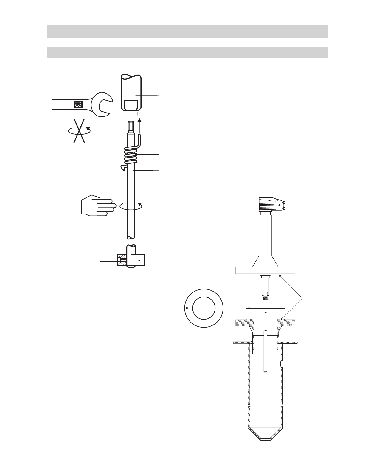
NRG 16-11S, step 1..............................................................................................................................12
NRG 16-11S, step 2..............................................................................................................................12
Attention............................................................................................................................................... 12
Important notes ....................................................................................................................................12
Tools.....................................................................................................................................................12
Installation
NRG 16-11S ...........................................................................................................................................6
Corrosion resistance ...............................................................................................................................7
Sizing .....................................................................................................................................................7
Name plate / marking .............................................................................................................................7
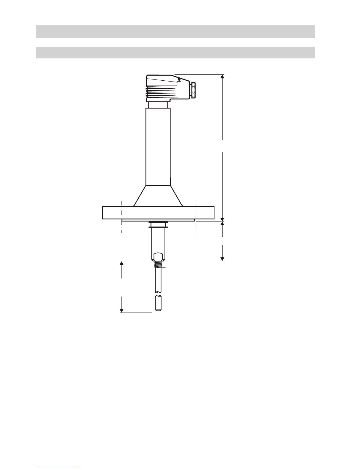
Dimensions NRG 16-11S ........................................................................................................................8
Technical Data
NRG 16-11S ...........................................................................................................................................9
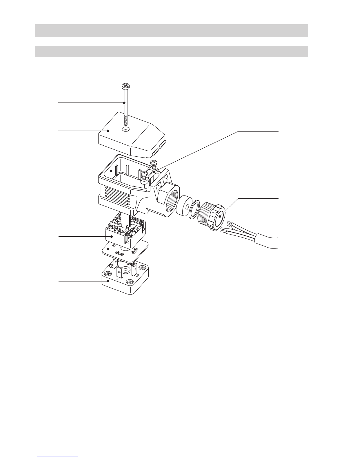
Key.......................................................................................................................................................11
Design
NRG 16-11S .........................................................................................................................................10
Key.......................................................................................................................................................11
Functional Elements