2
Contents
Usage for the intended purpose ..............................................................................................................5
Safety note .............................................................................................................................................5
Danger ...................................................................................................................................................5
Attention.................................................................................................................................................5
LV (Low Voltage) Directive and EMC (Electromagnetic Compatibility) .......................................................5
ATEX (Atmosphère Explosible).................................................................................................................5
Important Notes
Page
Explanatory Notes
Scope of supply......................................................................................................................................6
Description .............................................................................................................................................6
Function .................................................................................................................................................6
System components ...............................................................................................................................6
Design....................................................................................................................................................6
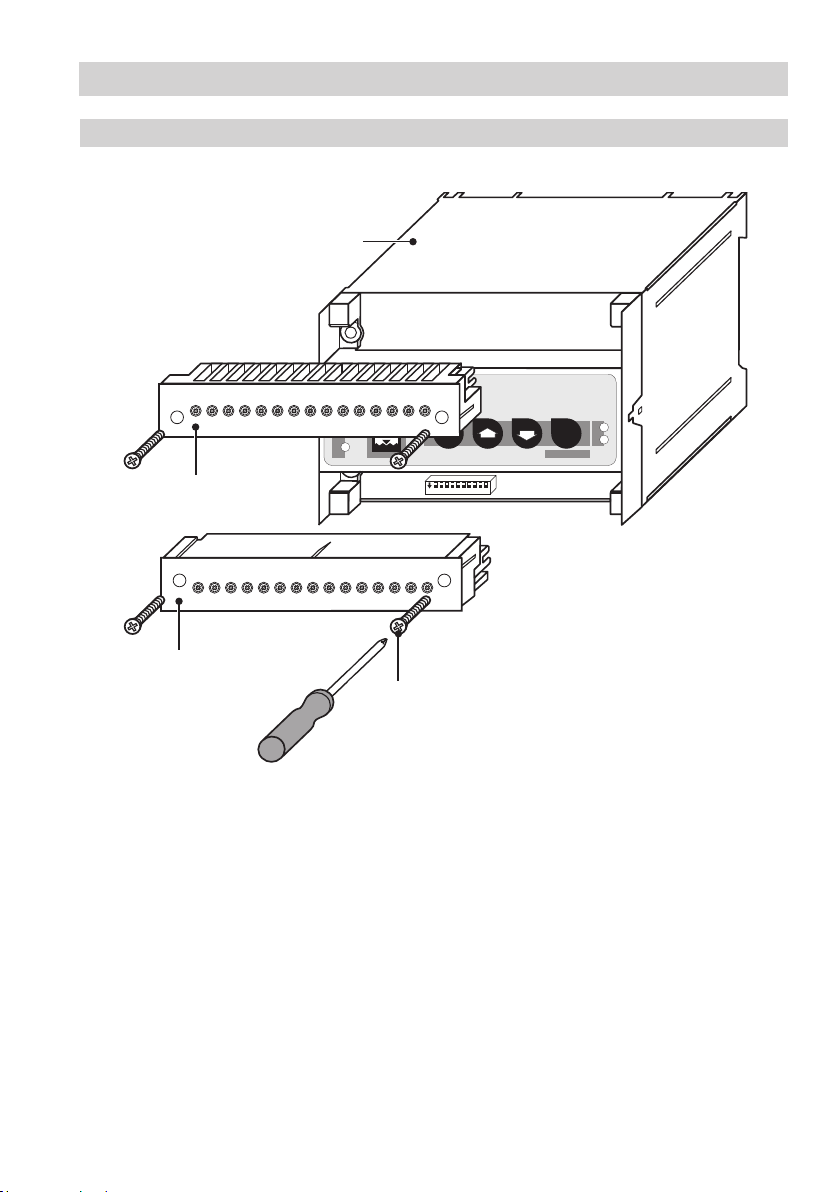
NRS 240..............................................................................................................................................11
Tools.....................................................................................................................................................11
Example of installation..........................................................................................................................12
Key.......................................................................................................................................................11
Installation
NRS 240................................................................................................................................................7
Corrosion resistance...............................................................................................................................8
Name plate / marking .............................................................................................................................8
Dimensions.............................................................................................................................................8
Technical Data
NRS 240................................................................................................................................................9
Key.......................................................................................................................................................11
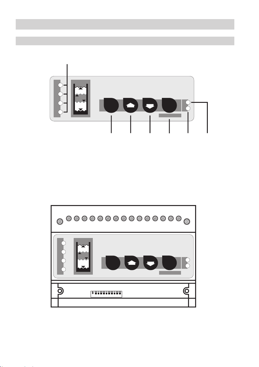
Design
NRS 240..............................................................................................................................................10
Key.......................................................................................................................................................11
Functional Elements