GEV FlammEx FMF 3170 User manual

Max. 14 Ct./Min aus dem deutschen Festnetz.
Mobil max. 42 Ct./Min.
International calls may vary.
GEV GmbH
Heidehofweg 16
25499 Tangstedt
Germany
www.gev.de
service@gev.de
Hotline: +49 (0)180/59 58 555
MONTAGE D
Funktionsweise
Das nachrüstbare Funk-Sende- & Empfangsmodul sendet und empfängt
Alarmsignale in Verbindung mit allen 9 V FlammEx Rauchwarnmeldern.
Durch die Systemcodierung wird ein hohes Maß an Übertragungssicherheit
gewährleistet. Das Modul überprüft alle 15 Sekunden auf eingehende Signale
und sendet kontinuierlich im Alarmfall, solange der Rauchwarnmelder aktiviert
ist.
FlammEx
Funk-Sende- & Empfangsmodul
FMF 3170
Art.-Nr.: 003170A, 003170B, 003170C
GB F NL PL
MA00093101
15UW01

Lieferumfang
1.
1.) Gehäuse
2.) Batteriefach
3.) Batterieanschluss
4.) Rastbefestigung für Rauchwarnmelder
5.) Montagelöcher
6.) Kodierschalter
7.) Anschlussleitung Alarmausgang (Interconnection)
8.) Clip zur Spannungsversorgung des Rauchwarnmelders
5
4
7
8
2
1
4
6
5
3
2
Folgende Punkte können unter anderem das Funksignal und die
Reichweite beeinträchtigen:
- elektrische Verbraucher (PC, TV, Kühlschrank, etc.)
- Dämmfolie, Alu-Folie, Hausverkleidungen
- Stahlbetonwände
- Handy, drahtloser Funk-Kopfhörer, andere Funkanlagen
- Fußbodenheizung (Heizdraht)
- Deckenleuchten, Leuchtstofflampen
- Kraftfahrzeuge in unmittelbarer Nähe
sowie größere und/oder metallische Geräte/Bauteile.
Wir empfehlen daher, vor fester Montage die Rauchwarnmelder
in die ausgewählten Räume zu legen und die Alarmauslösung
untereinander zu testen.
Testen Sie jede einzelne Einheit in regelmäßigen
Abständen und bei Veränderungen des Umfelds
(neuer Fußboden, neue oder umgestellte Möbel/
Leuchten, bauliche Veränderungen etc.).
Montagehinweise
2.
Wegen den Besonderheiten von Funkwellen, beachten Sie bitte
zusätzlich zu den Montagehinweisen des Rauchwarnmelders
folgende Punkte:
Metallwände, Stahlbeton-
Wände / Decken meiden
Großverbraucher meiden
Temperaturschwankungen und
feuchte Räume meiden
Abstand zwischen den
Funk-Modulen beachten
max. 25 m
D
mind. 1 m
3

3a) Damit die Melder untereinander kommunizieren
können, müssen alle zum gleichen System gehören-
den Melder die gleiche Codierung haben!
Um Fehlalarme zu vermeiden, z. B. Nachbarn die
auch ein FlammEx bidirektionales System benutzen,
sind verschiedene Systeme auch unterschiedlich zu
codieren.
Beispiel: 2-Familenhaus
Dabei sollte die Einstellung z. B. wie folgt vorgenommen
werden:
D
3c) In Kombination mit dem FlammEx Funkmodul benötigt
der FlammEx 9 V Rauchwarnmelder keine eigene
Batterieversorgung, er wird statt dessen vom Funkmodul
versorgt. Ecke der Batterieklappe des Rauchwarnmelders
für Kabelverbindung (8) abtrennen.
3b) Batterie in die Montagedose des Funk- Sende- & Empfangs-
modul einlegen, mit 9 V Batterieclip (3) von der Platine
verbinden.
Familie 1 Familie 2
1 2 3 4 5 6 7 8 9 10
ON
1 2 3 4 5 6 7 8 9 10
ON DIP
DIP
1 2 3 4 5 6 7 8 9 10
ON
1 2 3 4 5 6 7 8 9 10
ON DIP
DIP
Vorbereitung
3.
Kodierschalter
Kodierschalter
1. Familie
2. Familie
4 5

D
3e) Zum Ausprobieren (siehe Montagehinweise Punkt 2) den
Rauchwarnmelder auf das Funk-Sende- & Empfangsmodul
aufsetzen und im Uhrzeigersinn aufrasten.
Nase/Metallklammer leicht in Pfeilrichtung drücken, Deckel
schliessen, Nase einrasten lassen.
Ausführung B
Nase/
Metallklammer
Batteriefach-Deckel kann einfach geschlossen werden.
Ausführung A runder Knopf
Hinweis zum Schließen des Batteriefachs:
7
8
6 7
3d) Beim Anschluss des Kabels (7) an den
Rauchwarnmelder ist unbedingt auf die richtige
Polung zu achten!
schwarz = minus (-) rot = plus (+)

D
3g) Funk-Sende- & Empfangsmodul anbringen und Schrauben
festziehen.
Den Rauchwarnmelder auf das Funk-Sende- & Empfangsmodul
aufsetzen und im Uhrzeigersinn aufrasten.
3f) Nach erfolgreichem Test der Reichweite, den Rauchwarn-
melder und das Funk-Sende- & Empfangsmodul wieder
durch eine Drehung gegen den Uhrzeigersinn trennen.
Mit der Bohrschablone an der gewünschten (und voher
überprüften) Stelle Löcher bohren und Dübel einsetzen.
Schrauben bis ca. 0,5 cm eindrehen.
8 9

Frequenz 433,92 MHz
Spannungsversorgung 9 V Block-Batterie Alkaline
(nicht im Lieferumfang)
Übertragungsart bidirektional
Temperaturbereich 0 - 50°C
Reichweite ca. 25 m in Gebäuden, abhängig
von der baulichen Umgebung
Das Gerät ist zugelassen für den Vertrieb in der Europäischen
Gemeinschaft.
Hiermit erklärt die Firma GEV GmbH, dass sich dieses Gerät (Funk-
Sende- & Empfangsmodul FMF 3170) in Übereinstimmung mit
den grundlegenden Anforderungen und den anderen relevanten
Vorschriften der Richtlinie 1999/5EG befindet.
Die komplette Konformitätserklärung kann abgerufen werden unter:
www.gev.de
Batterie- und Akkuhinweise
Altbatterien dürfen nicht mit dem unsortierten Hausmüll
entsorgtwerden. Besitzer von Altbatterien sind gesetzlich
zur Rückgabeverpflichtet und können diese unentgeltlich
bei den Verkaufsstellen zurückgeben. Batterien enthalten
umwelt- und gesundheitsschädliche Stoffe und müssen
daher fachgerecht entsorgt werden.
Recycling-Hinweise
Dieses Gerät darf nicht mit dem unsortierten Hausmüll
entsorgt werden. Besitzer von Altgeräten sind gesetzlich
dazu verpflichtet, dieses Gerät fachgerecht zu entsorgen.
Informationen erhalten Sie von Ihrer Stadt- bzw.
Gemeindeverwaltung.
Fehleranalyse - Praktische Tipps
5.
Sollte ein FlammEx Funk-Rauchwarnmelder bei der
Alarmauslösung /Testbetrieb nicht mit anderen FlammEx Funk-
Rauchwarnmeldern kommunizieren können, überprüfen Sie
folgende Punkte:
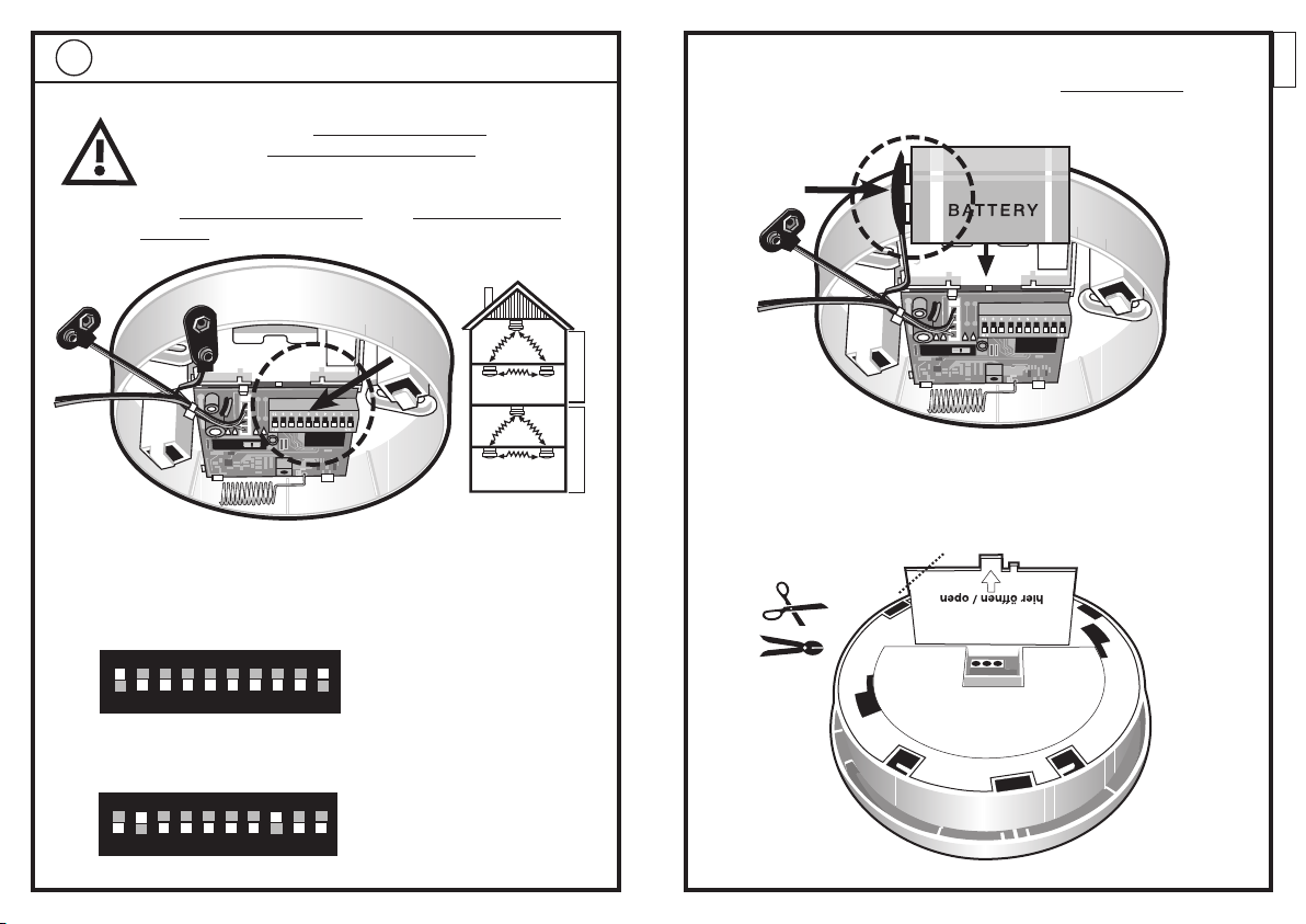
• DierichtigeEinstellungdesKodierschaltersbeiden
Funk-Sende- & Empfangsmodulen der anderen
System-Rauchwarnmelder prüfen - Codes müssen
identisch sein.
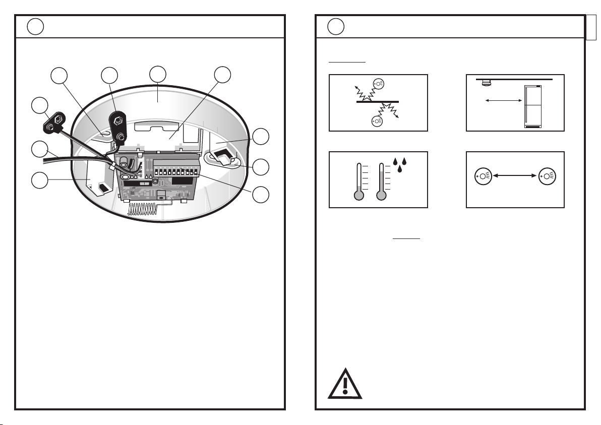
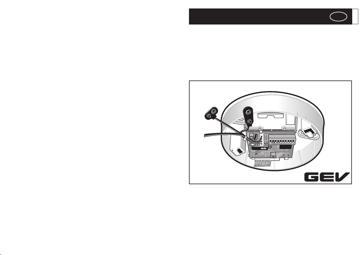
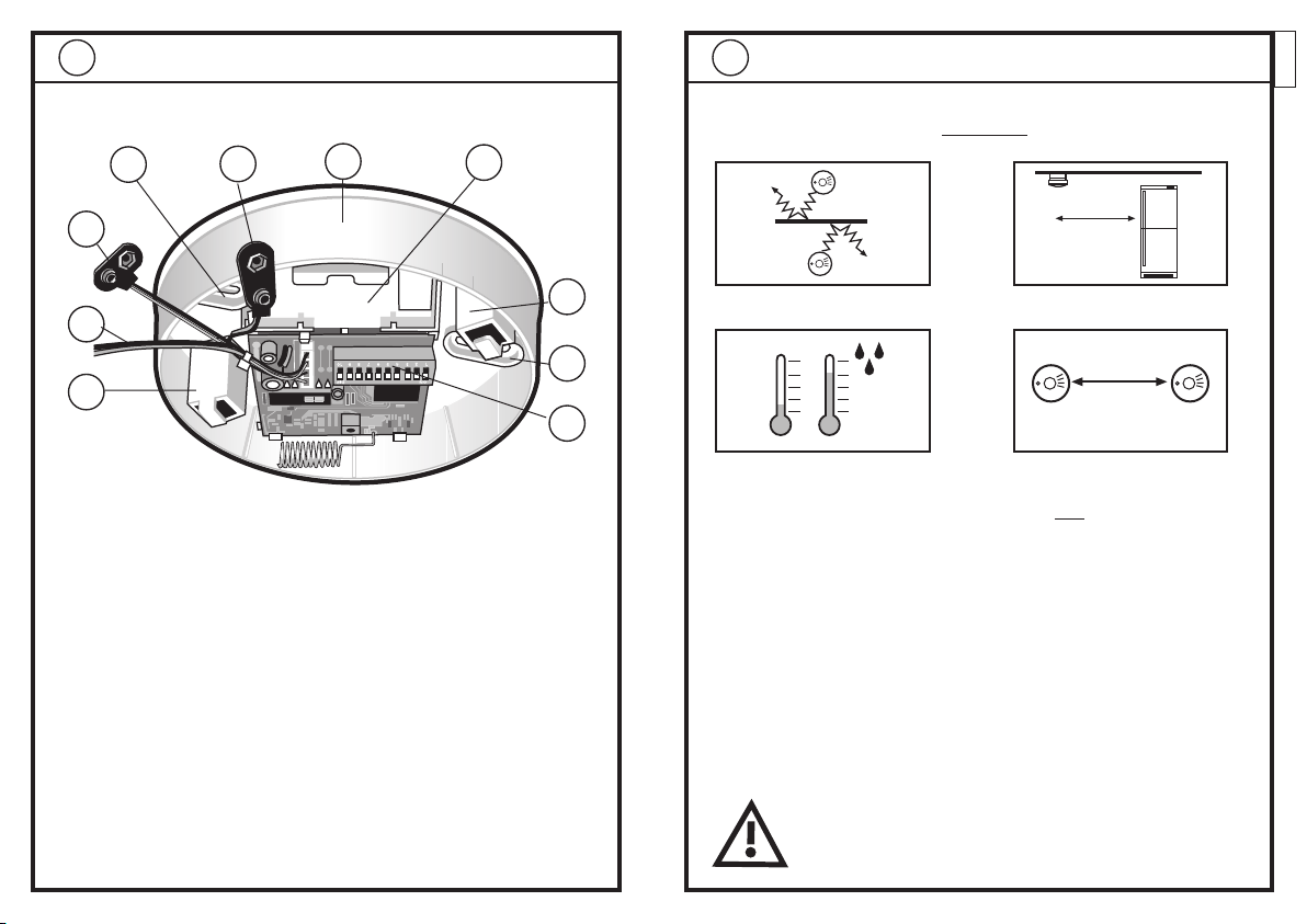
• PrüfenSiedieVerbindungderSignalkabel(7)
zwischen Rauchwarnmelder und Funk-Sende- &
Empfangsmodul.
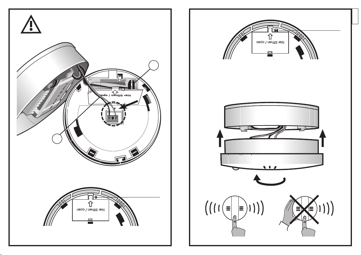
• BitteBatterieprüfen,gegebenfallstauschen.
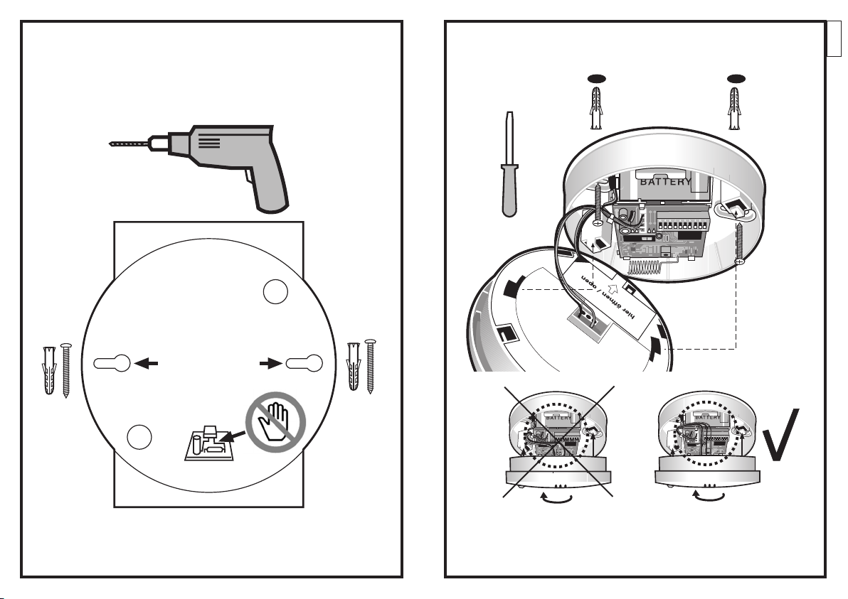
• BeachtenSiedieHinweiseunterKapitelMontage-
hinweise Punkt 2 - bauliche Gegebenheiten etc.
• DistanzzwischendenFunk-Rauchwarnmeldern
verringern, so dass jeder Funk-Rauchwarnmelder in
einem Verbund mit jedem anderen Funk-
Rauchwarnmelder Funksignale austauschen kann.
• PrüfenSiedieFunkstreckemiteinemanderen
Funk-Sende- & Empfangsmodul und
Rauchwarnmelder.
• PrüfenSieobeinanderesGerät,z.B.eindrahtloser
Funk-Kopfhörer, auf der gleichen Frequenz arbeitet
undeventuelldasFunksignalblockiert.Dieses
Problem stellt kein Mangel unserer Geräte dar!
Versuchen Sie bei dem störenden Gerät die
Frequenzen zu ändern, es abzuschalten oder wählen
Sie eine andere Codierung.
D
TechnischeDaten
4.
10 11

ASSEMBLY
Mode of Operation
The Radio Transmit and Receive Module, which can be fitted as an upgrade
to existing detectors, operates together with all 9 V FlammEx smoke
detectors to send and receive alarm signals.
Thesystemcodingensuresahighleveloftransmissionsecurity.Themodulelooks
forincomingsignalsevery15seconds,andtransmitscontinuouslywhenthereis
an alarm for as long as the smoke detector is active.
FlammEx
Radio Transmit and Receive Module
FMF 3170
Item no. 003170A, 003170B, 003170C
GB
GB
12 13

Amongst other factors, the following items can impair the radio
signal and the range:
- electrical equipment (PC, TV, fridge, etc.)
- insulating foil, aluminium foil, house panelling
- reinforced concrete walls
- mobile telephones and other radio equipment
- underfloor heating (electrical)
- ceiling lamps, fluorescent lamps
- particularly close motor vehicles
along with large and/or metallic devices or building components.
We therefore recommend that the smoke detectors are laid out
in the chosen rooms and the mutual alarm triggering tested
before they are permanently mounted.
Test each individual unit at regular intervals and
whenever the environment is changed (new floor,
new or moved furniture, lamps, structural changes
etc.)
Installation Instructions
2.
Because of the special features of radio transmissions, please
observe the following points in addition to the smoke detector‘s
assembly instructions:
Avoid metal walls and reinforced
concrete walls and ceilings
Avoid the neighbourhood of high-
powered electrical equipment
Avoid temperature variations
and damp areas
Maintain the correct distance
between radio modules
Max. 25 m
GB
At least 1 m
Supplied items
1.
1.) Housing
2.) Battery box
3.) Battery connection
4.) Engagement hook for smoke detector
5.) Mounting holes
6.) Coding switch
7.) Alarm output connecting lead (interconnection)
8.) Clip for smoke detector power supply
5
4
7
8
2
1
4
6
5
3
14 15

GB
3c) When combined with the FlammEx radio, the FlammEx 9 V
smoke detector does not require its own battery, as it is
powered by the radio module.
Remove the corner of the smoke detector‘s battery cover for
the cable connection (8).
3b) Insert the battery into the compartment in the Radio Transmit
and Receive Module, and connect it to the 9 V battery clip (3)
from the circuit board.
3a) It is necessary that all the alarms that belong to the
same system also have the same coding so that the
alarm units can communicate with one another!
Different systems must also be differently coded in
order to avoid false alarms, such as if neighbours are
also using a bidirectional FlammEx system.
Example: 2-family house
The setting should then be carried out, for instance, as
follows:
Family 1 Family 2
1 2 3 4 5 6 7 8 9 10
ON
1 2 3 4 5 6 7 8 9 10
ON DIP
DIP
1 2 3 4 5 6 7 8 9 10
ON
1 2 3 4 5 6 7 8 9 10
ON DIP
DIP
Preparation
3.
Coding switch
Coding switch
1st family
2nd family
16 17

GB
3e) To test the system (see assembly instructions, Point 2), place
the smoke alarm on the Radio Transmit and Receive Module,
and turn it clockwise until it engages.
Press the lug / metal clip gently in the direction of the arrow, close the
cover, allow the lug to engage.
Configuration B lug / metal clip
The battery box cover can be easily closed.
Configuration A round knob
Note concerning closure of the battery box:
3d) It is essential to observe the correct polarity when
connecting the cable (8) to the smoke detector!
black = minus (-) red = plus (+)
7
8
18 19

GB
3g) Attach the Radio Transmit and Receive Module and tighten
the screws.
Place the smoke detector on the Radio Transmit and Receive
Module, and turn it clockwise to engage.
3f) Once the range has been successfully tested, separate the
smoke detector and the Radio Transmit and Receive Module
again by turning them anti-clockwise.
Use the drilling template to drill holes and insert plugs at the
desired (and previously tested ) location. Turn the screws in
approx. 0.5 cm.
20 21

Fault finding - practical tips
5.
If,whenan alarmhasbeen triggeredorduring testing,aFlammEx radio
smokedetectorfails tocommunicatewithother FlammExradiosmoke
detectors, check the following points:
• CheckthecorrectsettingoftheCodingswitch
in the Radio Transmit and Receive Modules in the
other smoke detectors in the system - the codes
must be identical.
• Checkthatthesignalcable(7)isproperlyconnected
between the smoke detector and the Radio Transmit
and Receive Module.
• Checkthebattery,exchangeifnecessary.
• ConsiderthenotesunderPoint2oftheassembly
instructions section regarding the nature of the sur
rounding buildings etc.
• Reducethedistancebetweentheradiosmoke
detectors so that each radio smoke detector in the
same group can exchange radio signals with the
other radio smoke detectors.
• ChecktheradioconnectionusinganotherRadio
Transmit and Receive Module and smoke detector.
GB
TechnicalData
4.
Frequency 433,92 MHz
Power supply 9 V one piece alkaline battery
(not included)
Transmission type bidirectional
Temperature range 0 -50 °C
Transmission range approx. 25 m in buildings, depending on the
surrounding construction
Thedevice isapproved foroperationinside theEuropean Community.
GEV GmbH hereby declares that this device (Radio Transmit
and Receive Module FMF 3170) accords with the fundamental
requirementsandtheotherrelevantregulationsofguideline1999/5EG.
The full declaration of conformity can be seen under: www.gev.de
Battery and rechargeable battery information
Old batteries may not be disposed of with the unsorted
householwaste. Owners of used batteries are legally
obliged to recycle the batteries and can return them free
of charge to the place of sale. Batteries contain material
which is harmful to the environment and health, and must
therefore be disposed of professionally.
Recycling instructions
This device may not be disposed of with the unsorted
household waste. Owners of old devices are legally
obliged to professionally dispose of this device.
Contact your local council for further information.
22 23

MONTAGE
Fonctionnement
Ce module émetteur-récepteur radio, pouvant être ajouté à votre installation,
est compatible avec tous les détecteurs de fumées FlammEx 9 V et émet et
reçoit des signaux d’alarme.
Lecodesystèmegarantit unegrandesécuritédetransmission.Le modulecon-
trôle toutes les 15 secondes les signaux entrants ; en cas d’alarme, il émet en
continu, cela tant que le détecteur de fumées est activé.
FlammEx
Module émetteur-récepteur radio
FMF 3170
N° art. 003170A, 003170B, 003170C
F
F
24 25

Les cas de figure ci-dessous (liste non exhaustive) sont suscepti-
bles d’influer sur le signal radio ainsi que sur la portée :
- consommateurs électriques (PC, TV, frigo, etc.)
- films isolants, feuilles alu, revêtements de murs
- murs en béton armé
- portables, autres installations radio
- chauffage par le sol (fil de chauffe)
- plafonniers, lampes fluorescentes
- véhicules à proximité immédiate
ainsi que les appareils / constructions plus important(e)s et/ou métalliques.
C’est pourquoi nous vous recommandons, avant d’installer de
manière définitive les détecteurs de fumées, de les tester dans
les locaux dans lesquels ils sont prévus afin d’en vérifier le
déclenchement d’alarme.
Contrôlez chaque unité à intervalles réguliers et en
cas de changement dans l’environnement immédiat
(nouveau revêtement de sol, nouveaux meubles,
meubles déplacés, lampes, transformations, etc.).
Instructions de montage
2.
En raison de la particularité des ondes radioélectriques, veuillez
respecter les points ci-dessous, en plus des instructions de
montage du détecteur de fumées :
Évitez les parois métalliques ainsi que les
murs / plafonds en béton armé
Évitez les grands consomma-
teurs de courant
Évitez les écarts de température ainsi
que les locaux humides
Respectezunedistanceminima-
le entre modules radio
Max. 25 m
F
Min. 1 m
Pièces fournies
1.
1.) Boîtier
2.) Boîtier de pile
3.) Raccordement de pile
4.) Crochet de verrouillage pour détecteur de fumées
5.) Trous de montage
6.) Interrupteur de codage
7.) Ligne de raccordement pour sortie alarme
(interconnexion)
8.) Clip pour l’alimentation en tension du détecteur de
fumées
5
4
7
8
2
1
4
6
5
3
26 27

F
3c) Lorsqu’il est combiné au module radio FlammEx, le détecteur
de fumées FlammEx 9 V ne nécessite aucune alimentation
tension propre, il est alimenté par le biais du module radio.
Coupez le coin du couvercle de pile du détecteur de fumées
pour le raccordement du câble (8).
3b) Insérez la pile dans le boîtier de montage du module
émetteur-récepteur radio, puis raccordez-la au clip de pile
9 V (3) venant de la platine
3a) Afin qu’ils puissent communiquer entre eux, tous les
détecteurs faisant partie du même système doivent
avoir le même codage ! Afin d’éviter une fausse alar
me, par exemple si les voisins utilisent également un
système bidirectionnel FlammEx, les différents
systèmes doivent également avoir un codage
différent.
Exemple: maison abritant deux familles
Dans ce cas, on peut par exemple procéder au réglage
comme suit :
Famille 1 Famille 2
1 2 3 4 5 6 7 8 9 10
ON
1 2 3 4 5 6 7 8 9 10
ON DIP
DIP
1 2 3 4 5 6 7 8 9 10
ON
1 2 3 4 5 6 7 8 9 10
ON DIP
DIP
Préparation
3.
Interrupteur de codage
Famille 1
Famille 2
28 29

F
3e) Afin de procéder à un essai (voir instructions de montage,
point 2), placez le détecteur de fumées sur le module
émetteur-récepteur radio, puis verrouillez-le en le tournant
dans le sens des aiguilles d’une montre.
Appuyez légèrement sur le nez / l’attache en métal dans le sens de la
flèche, fermez le couvercle en laissant le nez s’encliqueter.
Version B
Nez / attache en
métal
Le couvercle de boîtier de pile se referme tout simplement.
Version A Bouton rond
Remarque concernant la fermeture du boîtier de pile
3d) Lors du raccordement du câble (8) sur le détecteur
de fumées, il convient de respecter la polarité !
noir = négatif (-) /rouge = positif (+)
7
8
30 31

F
3g) Mettez le module émetteur-récepteur radio en place, et
serrez les vis.
Placez le détecteur de fumées sur le module émetteur-
récepteur radio, puis tournez-le dans le sens des aiguilles
d’une montre.
32 33
3f) Après un test de portée réussi, séparez à nouveau le
détecteur de fumées et le module émetteur-récepteur radio
en les tournant dans le sens contraire des aiguilles d’une
montre. Grâce au gabarit de perçage, forez des trous à
l’emplacement souhaité (et auparavant testé) pour l’appareil,
et introduisez-y des chevilles. Vissez les vis jusqu’à environ
0,5 cm.

Analyse des dérangements – Conseils pratiques
5.
Si un détecteur de fumées FlammEx ne parvient pas à
communiquer avec les autres détecteurs de fumées FlammEx lors
d’un test ou lors du déclenchement d’une alarme, veuillez vérifier
les points ci-dessous :
• VérifiezleréglagecorrectduInterrupteurdecodage
auprès des modules émetteur-récepteur radio des
autres détecteurs de fumées du système – les codes
doivent être identiques.
• Vérifiezlebranchementducâbledesignal(7)entre
le détecteur de fumée et le module émetteur-récep-
teur radio.
• Veuillezvérifierlapile,remplacez-laéventuellement.
• Respectezlesinstructionsdemontagedonnéesau
point 2 - construction des locaux, etc.
• Réduisezladistanceentrelesdétecteursdefumées
radio de manière que chaque détecteur de fumées
radio au sein d’un assemblage puisse échanger des
signaux radio avec les autres détecteurs de fumées
radio.
• Vérifiezlalignehertzienneàl’aided’unautre
détecteur de fumée et module émetteur radio.
F
Caractéristiques techniques
4.
Fréquence 433,92 MHz
Alimentation en tension Pile alcaline monobloc 9 V
(pas comprise dans la livraison)
Mode de transmission bidirectionnel
Plage de températures 0 - 50 °C
Portée env. 25 m à l’intérieur de bâtiments,
selon le type de construction
L’appareil est autorisé à la vente dans les pays de la Communauté
Européenne.
Par la présente, la Firme GEV GmbH déclare que le présent
appareil (module émetteur-récepteur radio FMF 3170) est conforme
aux exigences de base et autres prescriptions applicables de la
Directive 1999/5/CE.
La déclaration de conformité complète peut être obtenue sous les
coordonnées suivantes : www.gev.de
Remarques concernant les piles et les batteries
Cet appareil ne doit en aucun cas être jeté avec les
ordures ménagères. Les propriétaires d‘équipements
électriques ou électroniques usagés ont en effet
l‘obligation légale de les déposer dans un centre de
collecte sélective. Informez-vous auprès de votre
municipalité sur les possibilités de recyclage.
Remarques concernant le recyclage
Les piles et accumulateurs usagés ne doivent en aucun
cas être jetés avec les ordures ménagères. Leurs
propriétaires ont en effet l‘obligation légale de les
ramener dans leur point de vente, où ils seront repris
gratuitement. Les piles et accumulateurs contiennent
des substances dangereuses pour l‘environnement et la
santé et doivent être recyclés selon la réglementation en
vigueur.
34 35

MONTAGE
Werking
De achteraf uit te rusten radio-zend- & ontvangstmodule zendt en ontvangt
alarmsignalen in verbinding met alle 9 V FlammEx rookmelders.
Doordesysteemcoderingwordteenhogemaataanoverdrachtszekerheidgega-
randeerd. Demodule controleertalle 15 seconden opinkomende signalen en zendt
continu in geval van alarm, zolang de rookmelder geactiveerd is.
FlammEx
Radio-zend- & ontvangstmodule
FMF 3170
NL
NL
Art.-nr. 003170A, 003170B, 003170C
36 37

De volgende punten kunnen onder andere het radiosignaal en de
draagwijdte verzwakken:
- elektrische verbruikers (pc, tv, koelkast, enz.)
- isolatiefolie, aluminiumfolie, huisbekleding
- muren van gewapend beton
- gsm‘s, andere radiozendinstallaties
- vloerverwarming (verwarmingsdraad)
- plafondlichten, TL-lampen
- motorvoertuigen in onmiddellijke nabijheid
evenals grotere en / of metalen toestellen / componenten.
Wij raden daarom aan vóór de vaste montage, de rookmelders
in de gekozen ruimten te leggen en de inwerkingstelling van het
alarm onderling te testen.
Test elke afzonderlijke eenheid met regelmatige
intervallen en bij veranderingen van de omgeving
(nieuwe vloer, nieuwe of verplaatste meubelen,
lichten, bouwkundige veranderingen enz.).
Montageaanwijzingen
2.
Omwille van de bijzonderheden van radiogolven dient u naast de
montageaanwijzing van de rookmelder bijkomend de volgende
punten in acht te nemen:
Metalenwanden,muren/plafondsvan
gewapend beton mijden
Grootverbruikers mijden
Temperatuurschommelingenen
vochtige ruimten mijden
Afstandtussenderadiomodulesin
acht nemen
max. 25 m
NL
min. 1 m
Leveromvang
1.
1.) Behuizing
2.) Batterijvak
3.) Batterijaansluiting
4.) Insluithaak voor rookmelders
5.) Montagegaten
6.) Codering-schakelaar
7.) Aansluitleiding alarmuitgang (interconnection)
8.) Clip voor de spanningsvoorziening van de rookmelder
5
4
7
8
2
1
4
6
5
3
38 39
This manual suits for next models
3
Table of contents
Languages:
Popular Transceiver manuals by other brands

Standart Horizont
Standart Horizont C520 owner's manual

uAvionix
uAvionix Ping1090 quick start guide

City Theatrical
City Theatrical Vero Net 7400-5708M Installation and quick start guide

Microwave Data Systems
Microwave Data Systems MDS entraNET 900 System guide

Midland
Midland 777 user manual

Yaesu
Yaesu FT-301 instruction manual