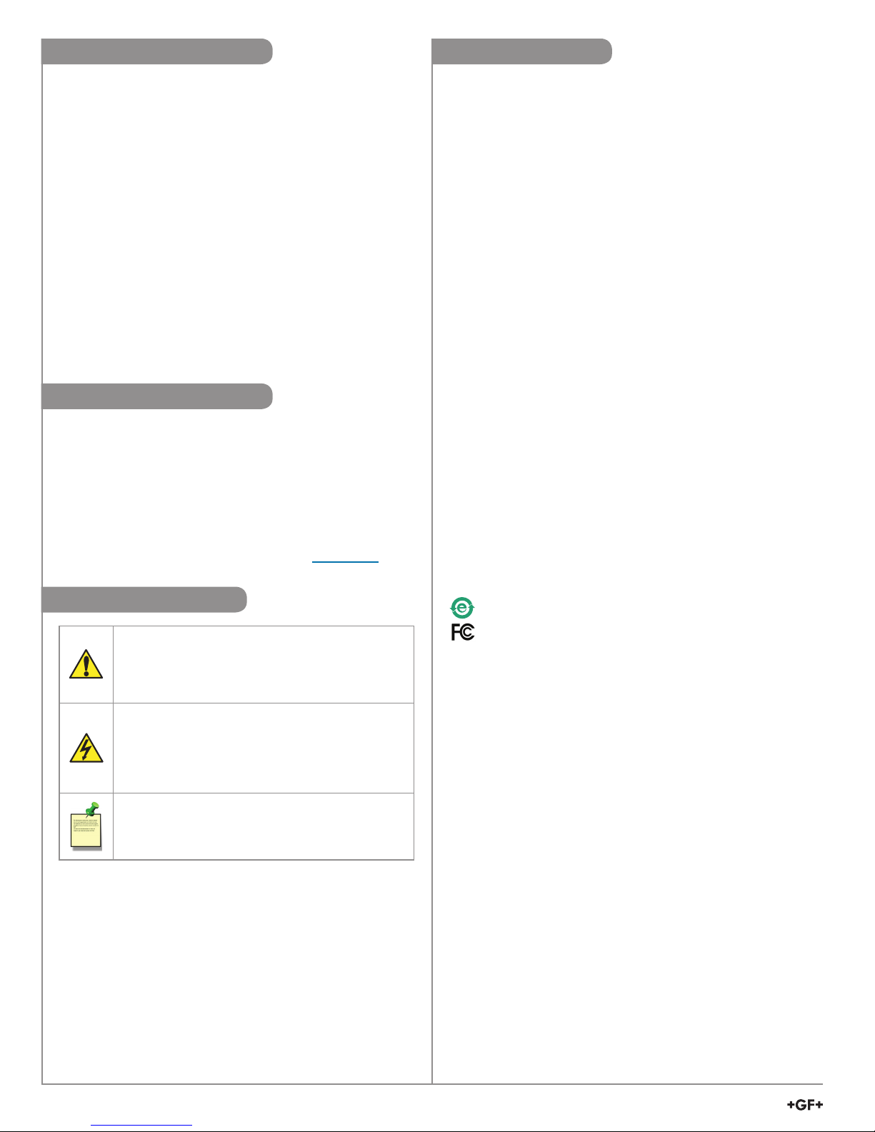
Caution / Warning / Danger
Indicates a potential hazard.
Failure to follow all warnings may lead to
equipment damage, injury, or death
Electrostatic Discharge (ESD) /
Electrocution Danger
Alerts user to risk of potential damage to product
by ESD,
and/or risk of potential of injury or
death via electrocution.
Note / Technical Notes
Highlights additional information or detailed
procedure.
Refer to your local Georg Fischer Sales ofce for the
most current warranty statement.
All warranty and non-warranty repairs being returned
must include a fully completed Service Form and
goods must be returned to your local GF Sales ofce
or distributor.
Product returned without a Service Form may not be
warranty replaced or repaired.
Signet products with limited shelf-life (e.g. pH, ORP,
chlorine electrodes, calibration solutions; e.g. pH
buffers, turbidity standards or other solutions) are
warranted out of box but not warranted against any
damage, due to process or application failures (e.g.
high temperature,
chemical poisoning, dry-out) or
mishandling (e.g. broken glass,
damaged membrane,
freezing and/or extreme temperatures).
Thank you for purchasing the Signet line of
Georg Fischer measurement products.
If you would like to register your product(s), you can
now register online in one of the following ways:
• Visit our website www.gfsignet.com.
Under Service and Support click on
Product Registration Form
• If this is a pdf manual (digital copy), click here
Warranty Information
Product Registration
Safety Information
Specications
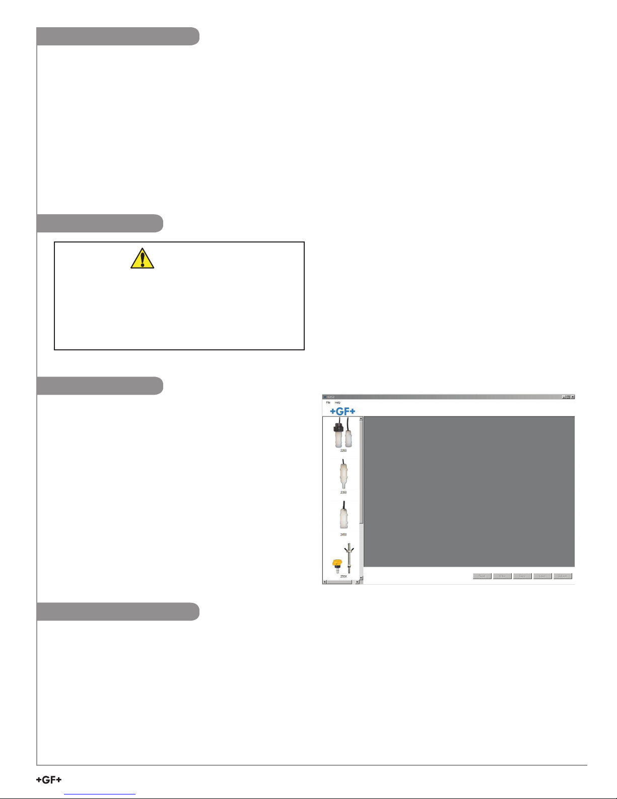
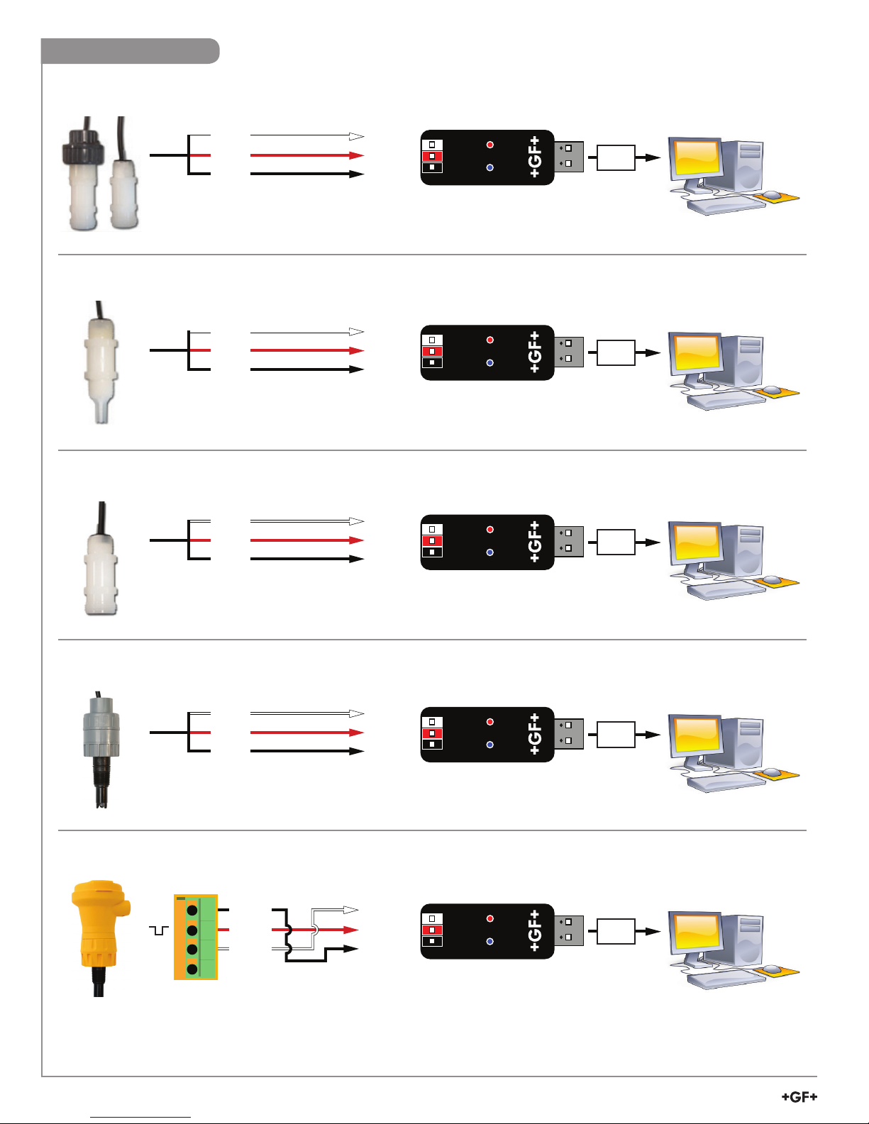
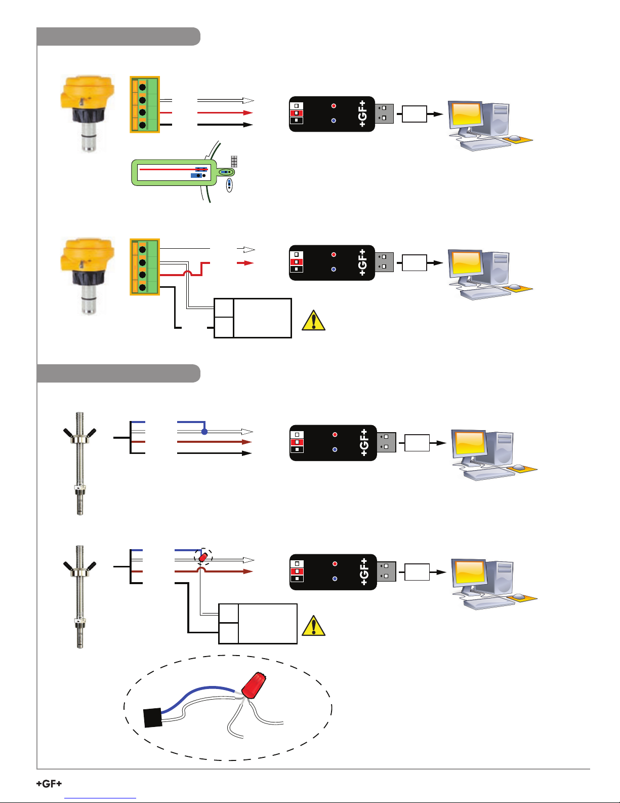
Compatibility
Signet Products ................... 2250, 2350, 2450, 2750, 2551,
2552, and 9900 Transmitter
Operating System................ Windows XP, Windows Vista,
Windows 7 (32 and 64 bit),
Windows 8, 8.1 (32 and 64 bit)
Windows 10 (32 and 64 bit)
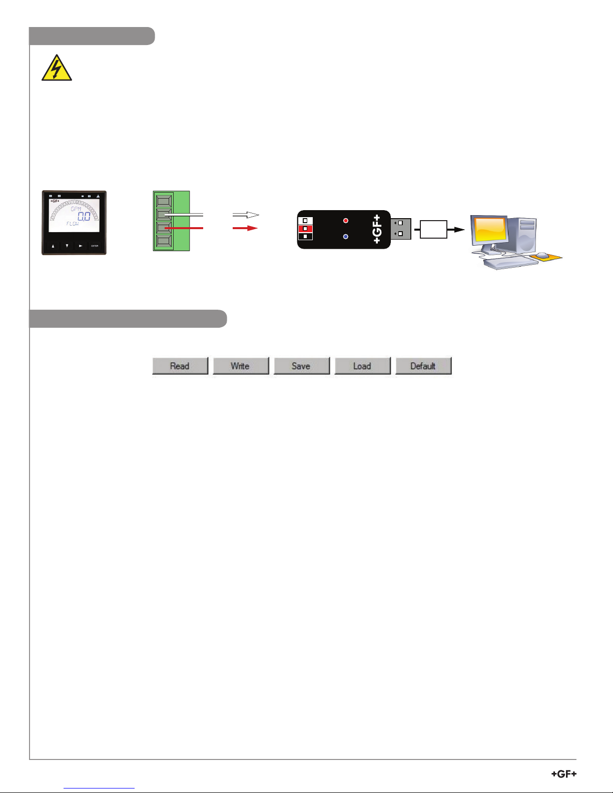
General
Enclosure............................. ABS
Red Indicator ....................... POWER ON
Blue Indicator....................... DATA COMMUNICATION
Input connections ................ 3-terminal connectors,
max. 14 AWG
Electrical
Communication rate ............ Maximum 19.2 kbs
Input power.......................... Supplied by USB interface
Output power....................... 5 VDC ± 5%
Power consumption............. 5 V @ 15 mA
Maximum current source..... 50 mA
Maximum cable ................... 300 m (1000 ft)
Environmental
Storage Temperature........... -20 °C to 100 °C
(-4 °F to 212 °F)
Relative Humidity................. 0 to 90% non-condensing
Operating Temperature........ -15 °C to 55 °C
(5 °F to 131 °F) (module only)
Shipping Weight ................ 0.22 kg (0.48 lb)
Standards and Approvals
CE, RoHS Compliant
China RoHS
This device complies with Part 15 of the FCC rules.
Operation is subject to the following two conditions:
(1) This device may not cause harmful interference, and,
(2) This device must accept any interference received,
including interference that may cause undesired
operation.
2Signet 0252 Conguration Tool