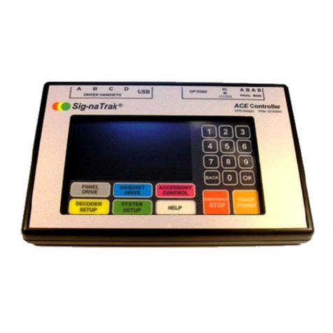
GFB Sig-naTrak ACE User manual

Sig-naTrak®Model railway electronics by GFB Designs
ACE (DCS2044)
DCC Controller
User Manual
(also includes use of the DRIVER handsets)

ACE DCC Controller User Manual DCS2044
V1.5 Last Updated: 28/09/2016
Page 2 of 48 Sig-naTrak®by GFB Designs
Introduction……
The ACE is the result of more than two years’ design and development work
and is a fully-featured model railway controller utilising the time-proven and
internationally-standardised Digital Command Control (DCC) system.
Despite its internal complexity, the ACE is simple to use as we have designed
it with you –the railway modeller –in mind. We want you to enjoy operating
your layout without having to worry about complicated technical issues or
computer jargon!
You naturally want to get “up and running” immediately, so we have included
the “Quick Start Guide”, starting on page 6 of this manual, to enable you to
drive your first train as soon as possible. However, we would encourage you
to read the whole of this manual carefully in order to fully understand all of the
features that the ACE offers.
Enjoy using the ACE, but please note that it is a “state of the art” piece of
equipment and needs to be treated as such! In particular……….
Take care not to knock or drop the ACE.
Use only your finger and/or the plastic stylus on the touch screen.
Do not operate the unit in damp, or excessively cold, environments.
THE ACE IS NOT A TOY and it should not be used by persons under
the age of 14 years unless supervised by an adult.
Do not make any electrical connections to the ACE other than as
described in this manual.
Do not power the ACE from any electrical source other than the
ZF120A-1504000 or ZF120A-1506000 power supply packaged with
the unit without first consulting GFB Designs.
Do not attempt to dismantle –or otherwise tamper with –the power
supply.

DCS2044 ACE DCC Controller User Manual
Last Updated: 28/09/2016 v1.5
GFB Designs. Page 3 of 48
CONTENTS
THE ACE FRONT PANEL 5
1 QUICK START GUIDE 6
1.1 DRIVING YOUR FIRST TRAIN! 8
1.2 ADDING AND OPERATING A SECOND TRAIN 9
1.3 WHAT NEXT? 9
2 OPERATION IN DETAIL 10
2.1 CONNECTING UP THE ACE 10
2.1.1 Power Input 10
2.1.2 Main Track Output 12
2.1.3 Programming Track Output 13
2.1.4 Connecting the DRIVER Handsets 14
2.2 GENERAL OPERATION 15
2.2.1 Startup 15
2.2.2 Track Power Control 15
2.2.3 Emergency Stop Features 16
2.2.4 Overload Protection 19
2.3 SYSTEM SETUP 20
2.3.1 Speed Steps 20
2.3.2 Consisting 20
2.3.3 Train List 23
2.3.4 Accessory List 24
2.3.5 Function Names 25
2.3.6 Audible Alarm 25
2.3.7 Display Brightness 26
2.4 HELP SCREENS 26
2.5 PANEL DRIVE MODE 27
2.5.1 Selecting the Train 27
2.5.2 Setting the Direction of Travel 28
2.5.3 Starting the Train and Controlling the Speed 28

ACE DCC Controller User Manual DCS2044
V1.5 Last Updated: 28/09/2016
Page 4 of 48 Sig-naTrak®by GFB Designs
2.5.4 Function Control –F0 (LIGHTS) to F4 29
2.5.5 Functions F5 to F28 29
2.6 HANDSET DRIVE MODE 30
2.6.1 Allocating Trains to Handsets 31
2.6.2 Controlling from the DRIVER Handset 31
2.7 TRANSFERRING TRAINS BETWEEN OPERATORS 33
2.7.1 Taking over a train 33
2.7.2 Taking a train back (“retrieving”) 33
2.8 ACCESSORY CONTROL MODE 34
2.8.1 Selecting an Accessory 34
2.8.2 Controlling the Accessory 34
3 DECODER SETUP 35
3.1 USING A PROGRAMMING TRACK 37
3.1.1 Initial Setup of Train/Locomotive Decoders 37
3.1.2 Initial Setup of Accessory Decoders 42
3.1.3 Initial Setup of Signal Decoders 43
3.2 PROGRAMMING ON THE MAIN TRACK 44
3.2.1 Configuring Train/Locomotive Decoders “on the main” 45
3.2.2 Configuring Accessories whilst on the Layout 46
3.2.3 Configuring Signals whilst on the Layout 46
4 IMPORTANT INFORMATION 48
4.1 DISPOSAL OF WASTE ELECTRICAL & ELECTRONIC EQUIPMENT 48
4.2 WARRANTY 48
4.3 DECLARATION OF CONFORMITY 48
4.4 CONTACT DETAILS 48

DCS2044 ACE DCC Controller User Manual
Last Updated: 28/09/2016 v1.5
GFB Designs. Page 5 of 48
THE ACE FRONT PANEL
NOTES
The MODE KEYS do not change their function and are always active.
This means that the mode of the ACE can be changed at will, even if
the controller has only partially completed an operation.
The numeric keypad keys, again, do not change their function.
However, the numeric keypad is only active when the controller is
expecting the entry of a number.
ALL ELECTRICAL CONNECTIONS ON
REAR PANEL
NUMERIC
KEYPAD
GRAPHIC DISPLAY
SCREEN AREA
TRACK POWER
ON/OFF KEY
EMERGENCY
STOP KEY
MODE
KEYS

ACE DCC Controller User Manual DCS2044
V1.5 Last Updated: 28/09/2016
Page 6 of 48 Sig-naTrak®by GFB Designs
1 QUICK START GUIDE
Follow these simple steps to start running……………
i) Carefully unpack the ACE, its power supply and accessories bag
containing the output connector and touch stylus.
ii) Locate the output connector and orientate it as shown here:-
iii) Insert a wire into each of the MAIN TRACK terminals, A and B, and
tighten the terminal screws. We recommend PCV-covered, stranded
wire with approximately 6 to 10mm of insulation stripped from the end.
See section (2.1.2) if you need advice on suitable wire sizes.
iv) Connect the free ends of each wire to either a section of track or your
layout, as shown below, and fully insert the connector into the matching
socket on the ACE –note that the connector’s screws face down.
v) Place your chosen locomotive (or train) on the test track (or layout).
(The exact method of connecting the wires to the track section, or your
layout, will vary in accordance with your setup and preferences. However,
we recommend that all wiring to track rails is soldered for reliability.)
Keep wires close together.
This helps prevent radio
interference radiation.
MAIN TRACK TERMINALS
A B

DCS2044 ACE DCC Controller User Manual
Last Updated: 28/09/2016 v1.5
GFB Designs. Page 7 of 48
vi) Plug the mains lead into the two-pin “figure of eight” socket on the
power supply and then insert the mains plug into a wall outlet. Switch on
the mains supply and check that the green indicator on the power
supply is illuminated.
vii)Insert the power supply’s DC plug into the “DC IN” socket on the ACE.
After a short delay (5 seconds) you will be presented with the SELF-TEST
SCREEN:-
The ACE will perform various internal tasks, turn on the MAIN TRACK power
and then display then PANEL DRIVE screen:-
Firmware version
Progress bar
Current speed
step
Reduces speed
by one step
Speed control
slider
Turn functions 0 to 4
On and off
(Shown all off)
Increases speed
by one step
Track current
Press to enter
train number
Previous train in
list
Next train in list
Access all
functions
(F0 to F28)
Direction control
Train name (if set) Train number (address)

ACE DCC Controller User Manual DCS2044
V1.5 Last Updated: 28/09/2016
Page 8 of 48 Sig-naTrak®by GFB Designs
1.1 DRIVING YOUR FIRST TRAIN!
As shown above, the panel drive screen is set up to drive a train with
locomotive address number 3 when first powered up (out of the box). This is
because DCC decoders for locomotives are set to address 3 at the factory.
If the decoder in the train you want to drive has already been set to another
address, proceed as follows:-
viii) Touch the key then type in your required number (address).
ix) Notice that the LOCO key has changed to . Now touch this key
to activate your entered address.
x) If your train has lights, try turning them on/off by touching the
key. Notice that the key turns to a lighter shade of blue, and changes
from a “3D” effect to “flat”, when the function (lights, in this case) is ON.
xi) Set the direction of your train by touching the DIR toggle. Notice that
the selected direction alternates, between FWD and REV, each time
you touch the toggle.
xii) Now press on the blue circular speed slider knob. Keeping pressure on
the circular knob, you can slide it right and left to start your train and
control its speed.
xiii) Fine adjustment of speed can be achieved more easily by using the….
and buttons. Each of these buttons changes the train’s
speed by one step, when it is momentarily touched. If you keep
pressure on either of these buttons, the train’s speed will “ramp” down
or up at the rate of about one speed step per second.
NOTE: The ACE operates with 128 speed steps by default (as supplied). This
gives a smooth, precise control over the train’s speed and is supported by all
modern DCC locomotive decoders. You can select 14, or 28, speed step
operation from the SYSTEM SETUP screen (see page 20) if you have an
older decoder which requires this.
LOCO
ENTER
LIGHTS
INC
DEC

DCS2044 ACE DCC Controller User Manual
Last Updated: 28/09/2016 v1.5
GFB Designs. Page 9 of 48
1.2 ADDING AND OPERATING A SECOND TRAIN
To operate another train, proceed as follows:-
i) Place the second train on the track –it must obviously have a decoder-
equipped locomotive or power car! Ensure that it cannot collide with your
first train!
ii) Select the address (number) of the second train/locomotive by touching the
key and then typing the address using the numeric keypad. Again,
the LOCO key will change to . Touch this key to activate your
second train’s address.
iii) You are now in control of the second train! It can be driven from the panel
as described in section (1.1) above whilst the first train continues as
previously commanded (i.e. it will continue to run if it was already moving
when the second train was selected).
iv) To return control to the first train, touch the key. Notice that the
second train continues as previously commanded.
v) To regain control of the second train, touch the key. Notice that
the first train continues as previously commanded.
vi) You can now use the PREV/NEXT keys, as you wish, to swap control
between the two trains.
THIS COMPLETES THE BRIEF INTRODUCTION TO DRIVING TRAINS
WITH THE ACE –WELL DONE SO FAR !
1.3 WHAT NEXT?
The following sections of this guide describe the operation of the ACE in more
detail, allowing you to explore all of its features. You do not necessarily need
to read them in order but we would encourage you to cover all sections at your
leisure.
Most modellers will probably want to use our DRIVER handsets for train
control –this is covered in sections (2.1.4) and (2.6) on pages 14 and 30.
LOCO
ENTER
PREV
NEXT

ACE DCC Controller User Manual DCS2044
V1.5 Last Updated: 28/09/2016
Page 10 of 48 Sig-naTrak®by GFB Designs
2 OPERATION IN DETAIL
In addition to explaining the operation of the ACE controller, this manual is
also intended to give related general advice with regard to the use of Digital
Command Control. We hope that this will be useful if you are a newcomer to
the world of DCC.
However, it is impossible to cover all necessary information “from the ground
up” and so you may find it necessary to consult one of the several excellent
DCC textbooks available. Also, it will be necessary to refer to the instruction
manuals for your DCC decoders and/or locomotives.
Experienced DCC users will inevitably find some of the advice and information
in this manual repetitive and may wish to skip the relevant sections.
2.1 CONNECTING UP THE ACE
To control a layout, you will need a minimum of the “Power Input” and the
“Main Track Output” – additional connections will depend upon your
requirements.
2.1.1 Power Input
The ACE is packaged with a suitable power supply for use with model
railways, from N to O gauge, with a layout area of up to around 20m2(square
metres –or around 60 square feet)
1
. There are two standard power supplies:-
i) The ZF120A-1504000.
Used with the standard ACE –DCS2044 –supporting a maximum track
output current of 3.5amp. This will normally supply sufficient current for the
running of up to 6 to 8 OO gauge trains (depending upon loading, gradients
etc.).
i) The ZF120A-1506000.
Used with the high-power ACE –DCS2044H –supporting a maximum
track output current of 5.0amp. This is recommended for O gauge (or
larger) layouts.
The ZF120A-1504000 power supply is shown below:-
1
It is expected that such layouts would have a maximum of around six to eight trains
running at any one time.

DCS2044 ACE DCC Controller User Manual
Last Updated: 28/09/2016 v1.5
GFB Designs. Page 11 of 48
(The ZF120A-1506000 is similar, but slightly larger)
NOTE: Both of the above power supplies provide a nominal 15volt (V)
smooth, regulated direct current (DC) output. This ensures a
controlled track voltage from the ACE of around 14V, as stated in the
National Model Railroad Association (NMRA) standards.
To provide (turn on) the power input:-
i) Firmly and fully insert the AC CONNECTOR on the mains lead into the AC
RECEPTACLE on the power supply. Plug the MAINS PLUG into a
domestic (240V) mains outlet and switch on the mains supply at the outlet.
ii) Ensure that the LED INDICATOR, on the power supply, is glowing.
iii) Fully insert the DC PLUG into the “DC IN” socket on the rear panel of the
ACE. This turns on the internal circuitry and starts the operation of the unit.
To turn off the power input:-
i) Remove the “DC PLUG” from the “DC IN” socket on the ACE.
NOTE: Allow at least three seconds from power removal before re-applying
power. Failure to observe this recommendation may disturb the
operation of the internal microcomputer and may affect data storage.
Use of other power supplies
Generally, DON’T ! The ZF120A units have been carefully chosen, and tested
by us, for compatibility with the ACE and for compliance with European safety
standards.
However, there are circumstances where a different operating voltage is
desirable (e.g. lower for smaller scales, higher for larger scales than O gauge)
and the ACE can accept an input of between 12 to 22V.
AC CONNECTOR
AC
RECEPTACLE
LED
INDICATOR
DC PLUG

ACE DCC Controller User Manual DCS2044
V1.5 Last Updated: 28/09/2016
Page 12 of 48 Sig-naTrak®by GFB Designs
PLEASE ENSURE THAT……
A SMOOTHED DC supply is used.
Absolute maximum voltage is 24V –a REGULATED supply is
preferable.
The supply must have built-in protection against short-circuits.
TRADITIONAL TRANSFORMERS, OR OTHER MODEL RAILWAY
CONTROLLERS, MUST NOT BE USED UNDER ANY
CIRCUMSTANCES!
We suggest that you contact GFB Designs (details on page 48) for advice
regarding non-standard operating voltages.
2.1.2 Main Track Output
The DCC power to operate your layout is supplied from an internal booster
circuit and appears on the terminals. Terminal A is connected to
one rail of your track, and terminal B is connected to the other rail, as
illustrated in section (1), page 6.
As the DCC signal is alternating current in nature, it is not usually critical as to
which rail/terminal is which. HOWEVER, it is possible to drive a single non-
decoder-equipped (i.e. DC) locomotive on the layout, using an address of 0
(zero). Under this circumstance, terminal A will assume a positive potential
when the forward direction is selected (and negative with reverse selected).
Selection of wire type and size
We recommend PVC-covered stranded “equipment wire” which is available
from www.signatrak.co.uk, most model railway retailers, and all electronic
component suppliers. In the UK, the gauge of the wire is specified by the
number and diameter of the internal conducting wire strands –commonly used
sizes, and typical current ratings, are:-
7/0.2mm (7 strands of 0.2mm dia) 1.4A
16/0.2mm (16 strands ……) 3.0A
24/0.2mm (24 …….) 4.5A
32/0.2mm (32 …….) 6.0A
The “rule of thumb” is generally “the thicker, the better” but – for practical
purposes –we recommend 16/0.2 for small layouts, with no more than about
three 00 trains running. 24/0.2 or 32/0.2 will be beneficial for larger setups.
A B
MAIN

DCS2044 ACE DCC Controller User Manual
Last Updated: 28/09/2016 v1.5
GFB Designs. Page 13 of 48
Note that the wire’s current rating per se is not the governing factor here – the
main desire is to minimise the overall cable resistance in order to keep voltage
drops as low as possible.
Whilst discussing voltage drops, it is worth pointing out that the majority of
these arise from bad connections –either due to poor soldering, or loose
screw terminals. NEVER RELY UPON TWISTING BARE WIRES TOGETHER
TO MAKE ELECTRICAL CONNECTIONS!
2.1.3 Programming Track Output
Most decoder setup –or programming –is performed using DCC signals with
a specially-limited current output, in accordance with NMRA standards. The
ACE provides the “PROG. A B” output for this purpose. Usually, a section of
track on your layout will be dedicated as a PROGRAMMING TRACK and used
for the setting up of locomotive decoders.
Both rails on the programming track should be electrically-isolated from the
rest of your layout and should then be connected to the ACE’s “PROG. A B”
terminals. This ensures that the current limiting circuitry in the ACE will give a
degree of protection to your decoder in the event of wiring faults. A typical
scheme is shown below:-
Ensure that any two wires, in a pair carrying DCC signals, are kept close
together and NOT arranged in a loop. This is because the wire could
otherwise act as an antenna and unintentionally radiate components of the
DCC signal, causing possible interference to other equipment. The ACE has
been designed in accordance with the relevant European standards in order to
minimise such effects.
Insulating
joiners
PROGRAMMING TRACK
MAIN TRACK

ACE DCC Controller User Manual DCS2044
V1.5 Last Updated: 28/09/2016
Page 14 of 48 Sig-naTrak®by GFB Designs
2.1.4 Connecting the DRIVER Handsets
The DRIVER handset (part no: BHS1204) provides a low-cost means of
adding up to four additional operators and/or giving a more traditional “knob
and switches” method of control. A DRIVER can be plugged into any of the
A, B, C or D sockets on the rear panel of the ACE, using the supplied cable.
NOTE: DO NOT PLUG ANY OTHER TYPE OF DEVICE INTO THESE
SOCKETS! They are protected by an internal fuse but this is NOT user-
replaceable.
Basic DRIVER features –see sections (2.6) and (2.7) for more details
Control of speed, direction, DCC functions F0 to F4 and emergency stop is
provided. Functions F5 to F28 can be controlled via the ACE’s panel.
Train allocation to the DRIVER is carried out from the HANDSET DRIVE
screen on the ACE, corresponding to dispatching on full-size railways.
Once the train is running, the handset can be locked out, unplugged and
moved around your layout without interrupting the train’s movement.
The handset can then be plugged in again –perhaps on an extended lead
–and unlocked, to resume driving.
Trains can be swapped between handsets –or between a handset and the
ACE’s panel control – using the HANDSET DRIVE mode/screen.
DIRECTION
SWITCH
SPEED CONTROL
KNOB
EMERGENCY STOP
BUTTON
FUNCTION
BUTTONS
CABLE SOCKET

DCS2044 ACE DCC Controller User Manual
Last Updated: 28/09/2016 v1.5
GFB Designs. Page 15 of 48
2.2 GENERAL OPERATION
All users should have a working knowledge of this section (2.2) as it deals with
fundamental features of the ACE which may be required at any time.
Use of the touch keys –If you are not familiar with touch panels, you may
find that it takes a little practice to establish consistency with the operation of
the keys. “Touching” a key, requires positive pressure –using either your
finger or the supplied stylus –for about half a second. A lighter, or faster,
touch may not be detected. Sometimes, it is necessary to maintain the
pressure on a key, for certain functions, and this is stated where required.
2.2.1 Startup
As the ACE is a microcomputer-controlled device, it needs to perform a
precise sequence of operations –from power application - in order to start
running correctly. The start-up sequence takes approximately four seconds
and consists of:-
Microcomputer initialisation.
Display initialisation (the screen will flash –this is normal).
Self-test (checking of internal data and some hardware functions).
Retrieval of the train list, accessory list, function key names and data
relating to your last operating session.
Entry to PANEL DRIVE mode.
Note that, during the start-up sequence, the track power is held OFF.
Immediately prior to PANEL DRIVE entry, the MAIN A B track power is turned
on and a stream of approximately 30 DCC reset packets –followed by a
similar number of idle packets - is transmitted to ensure that all decoders on
the layout start in a defined state.
2.2.2 Track Power Control
The button is used to turn the “MAIN A B” output on and off.
It can, therefore, “kill” the power to your entire layout and should obviously be
used with care in a multi-operator situation! Bear in mind that –upon
restoration of the power –devices on the layout may not be in their previous
states. For example:-
TRACK
POWER

ACE DCC Controller User Manual DCS2044
V1.5 Last Updated: 28/09/2016
Page 16 of 48 Sig-naTrak®by GFB Designs
All trains will be reset to STOP.
Some train functions (e.g. lights, sound etc) may be reset to OFF.
(Note –this is a feature of the decoder, not the ACE)
Accessories (e.g. points, signals etc) may not reset to the expected
position (depending upon the device, its manufacturer and its
settings).
Hence, we recommend that the TRACK POWER OFF feature is used only
when power removal is essential - e.g. if work on the track is required. For
emergency situations –i.e. the rapid stopping of one, or all, train(s) –we
suggest the EMERGENCY STOP features, described below.
To turn track power off:-
Touch the button when the power is on. In PANEL DRIVE, HANDSET DRIVE
or ACCESSORY CONTROL modes you will see the following display………
POWER OFF
……which will replace the track current value in the top right-hand corner of
the graphics screen.
To turn track power on:-
Touch the button when the power is off. In PANEL DRIVE, HANDSET DRIVE
or ACCESSORY CONTROL modes you will see that the track current value is
restored, e.g.………
0.32A
……..in the top right-hand corner of the graphics screen.
2.2.3 Emergency Stop Features
The key can be used to bring one –or all –trains to an immediate
halt. In cases where a potential collision is observed, or a point is about to be
traversed when set incorrectly, it may not be satisfactory to simply set “stop”
(i.e. speed step 0) on the controller or handset. This is because the
locomotive’s decoder may have a deceleration value set and it would take too
long for the train to stop!
EMERGENCY
STOP

DCS2044 ACE DCC Controller User Manual
Last Updated: 28/09/2016 v1.5
GFB Designs. Page 17 of 48
Stopping a train quickly (PANEL DRIVE):-
Touching the EMERGENCY STOP button will send a special DCC instruction
over the track which will immediately stop the locomotive currently being
driven from the panel –i.e. it is train-specific.
You will see: EMGY –STOP which replaces the track current display.
Note that the speed slider, and “SPEED” (steps) display are reset to zero.
Recovering from emergency stop (PANEL DRIVE):-
Simply touch the EMERGENY STOP button again. The track current display
will be restored.
Stopping ALL TRAINS quickly (PANEL DRIVE):-
If you maintain pressure on the EMERGENCY STOP key for about 1.5
seconds, the ACE will immediately stop all trains on the layout.
You will see: ALL E–STOP which replaces the track current display.
The speed slider, and “SPEED” (steps) display are, again, reset to zero.
NOTE - In this condition, the ACE sends broadcast emergency stop
instructions to the track (the NMRA standards specify that ALL locomotive
decoders must respond). The track power is NOT turned off.
Recovering from ALL E-STOP
Simply touch the EMERGENY STOP button again. The track current display
will be restored.
NOTE, also, that this action is used to recover from an ALL E-STOP condition
commanded from a DRIVER handset –see below.

ACE DCC Controller User Manual DCS2044
V1.5 Last Updated: 28/09/2016
Page 18 of 48 Sig-naTrak®by GFB Designs
Stopping a train quickly (HANDSET DRIVE):-
Pressing the button on a DRIVER handset momentarily –i.e. for
about 0.5 seconds –will bring the train currently controlled from that
handset to an immediate stop. All other activity on the layout will continue.
In order to alert other operators, the track current display on the ACE is
replaced with:-
H/S E-STOP
This condition applies to the specific train being driven from the handset in
question. Track power is NOT turned off.
Recovering from emergency stop (HANDSET DRIVE):-
Recovery from emergency stop initiated from a DRIVER handset is rather
different from panel drive mode. H/S E-STOP is reset by turning the relevant
DRIVER’s speed control knob fully anti-clockwise (i.e. to “MIN” or normal
stop position).
Once the knob is returned to MIN, the track current display on the ACE is
restored.
Stopping ALL TRAINS quickly (HANDSET DRIVE):-
Holding the STOP button on a DRIVER handset pressed for longer than
around 2 seconds will force the ACE to immediately stop all trains on the
layout. You will see the
ALL E-STOP display on the ACE’s panel.
To restore driving, you must:-
i) Touch the key on the ACE.
ii) Turn the DRIVER’s speed control knob fully anti-clockwise.
NOTE that the DRIVER’s speed control knob only affects the train controlled
by the handset in question.
EMERGENCY
STOP

DCS2044 ACE DCC Controller User Manual
Last Updated: 28/09/2016 v1.5
GFB Designs. Page 19 of 48
The following sections give a “guided tour” of the ACE’s screen
displays and describe the associated operating modes and features.
2.2.4 Overload Protection
Like all DCC controllers, the ACE has electronic protection circuitry built in to
the outputs of its boosters.
MAIN A B (track) output
In the event of an overload or short-circuit between the A and B terminals, the
following will occur:-
i) The DCC output will be immediately turned off.
ii) The ACE will wait about one second.
iii) The output will be turned back on (“retry”).
This cycle repeats until the overload is removed and the audible alarm (high-
pitched buzzer) will sound. You will also be presented with the following
display –overlaid on the current screen:-
An “overload” is defined as a current draw – however brief - between the A
and B outputs, of more than around 3.6A. If you have the high-power version
of the ACE (DCS2044H), this limit is increased to about 5.5A.
PLEASE NOTE –Whilst the controller has been designed to withstand
constant overloads, and will continue in its “output cycling” state indefinitely,
this is NOT a desirable situation as it could lead to issues such as cable over-
heating or, ultimately, damage to decoders and other layout devices.
ALWAYS CORRECT OVERLOADS AND SHORT-CIRCUITS IMMEDIATELY!
PROG A B (programming) output
The (decoder) programming track output has special protection characteristics
as defined by the NMRA. It is designed to protect both the ACE and decoders,
and further details are given in section (3.1).
OVERLOAD !!
Check for short-circuits or de-railments

ACE DCC Controller User Manual DCS2044
V1.5 Last Updated: 28/09/2016
Page 20 of 48 Sig-naTrak®by GFB Designs
2.3 SYSTEM SETUP
SYSTEM SETUP mode is entered by touching the key.
The mode can be selected at any time BUT please note that the track power is
turned OFF during SYSTEM SETUP. This is because most of the system
setup features have a fundamental effect on train and layout operation so their
behaviour could be unpredictable if left running!
Upon touching the system setup mode key, the MAIN A B track outputs are
immediately turned off and the following screen appears:-
2.3.1 Speed Steps
Any ONE of “14”, “28” or “128” can be selected. We recommend the use of
128 speed steps as this gives the most precise and smoothest control of the
trains’ speed (i.e. best resolution). All modern locomotive decoders support
128 speed steps.
The lower resolution –14 and 28 –speed step modes have been included to
support early decoders. If you need to use either of these, your newer
decoders will still work but you will lose their 128 speed step capability.
NOTE: In 14 speed step mode, the locomotive’s lights control information is
combined with speed instructions. Your decoder must be correctly configured
for this –see section (3.1.1).
2.3.2 Consisting
Consisting is the grouping of two or more locomotives (or multiple-unit power
cars) on a single train (e.g. “double-heading”). The ACE will allow up to six
locomotives in a single consist which works as follows:-
SYSTEM
SETUP
Other manuals for Sig-naTrak ACE
1
This manual suits for next models
1
Table of contents
Other GFB Controllers manuals
Popular Controllers manuals by other brands
Show Tec
Show Tec Fademaster 16 manual
Ebmpapst
Ebmpapst CN1116 Operating and maintenance instructions
Black Box
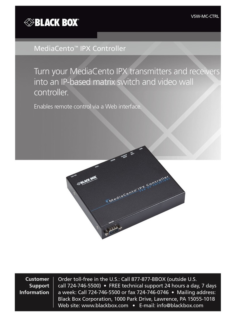
Black Box VSW-MC-CTRL MediaCento IPX Controller user guide
WindowMaster
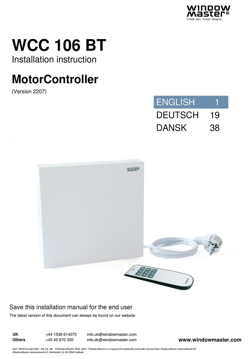
WindowMaster MotorController installation instructions
Delta
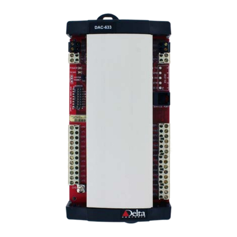
Delta DAC-633 installation guide

NovaStar
NovaStar MBOX600 user manual
