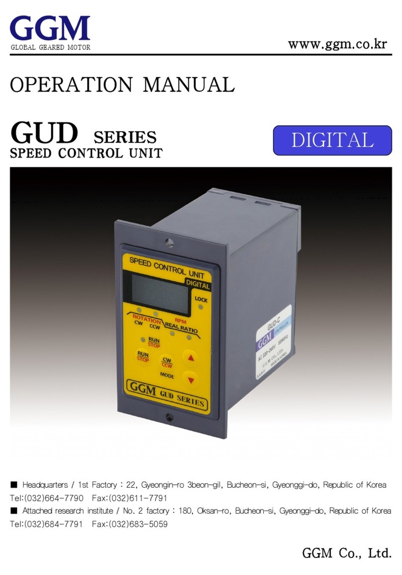
GGM GUS Series User manual

www.ggm.co.kr
OPERATION MANUAL
GUSSERIES
SPEED CONTROL UNIT
■Headquarters / 1st Factory : 22, Gyeongin-ro 3beon-gil, Bucheon-si, Gyeonggi-do, Republic of Korea
Tel:+82-32-664-7790 Fax:+82-32-611-7791
■Attached research institute / No. 2 factory : 180, Oksan-ro, Bucheon-si, Gyeonggi-do, Republic of Korea
Tel:+82-32-684-7791 Fax:+82-32-683-5059
GLOBAL GEARED MOTOR
SEMI DIGITAL

Thank you for purchasing a GGM product.
To ensure that you areusing this product correctly, make sure to first read this operation
manual thoroughly and familiarize yourself with allknowledge, safety information and
precautions related tothe product. After you have read this operation manual, keep it
at hand for reference whenneeded.
1. Safety precautions
In usingand operating the product, be sure to observe the following precautions. Failure to
observe the precautions may result in electric shock, injury or fire. The following precautions
are very important and should be observed at all times.
•Do not use the product near explosive materials, combustible materials,flammable
gas, corrosive materials, or anyplace where it may be splashed by water.
Doing so may cause fire, electric shock or injury.
•Do not forcibly bend, pull or insert the motor lead wire.
Doing so may cause fire or electric shock.
•Do not move, install, connect or inspectthe product while an electric current
is being applied. Be sure to only perform repair or installationwork after
cutting off the power supply.
Failure to do so may cause an electric shock.
•Have a qualified person with relevant knowledge install, connect,
operate, control and check the product for failure.
Doing so may cause fire, electric shock or injury.
•After cutting off the power supply, allow a full minute to elapse before touchingthe
output terminal. Failure to do so may cause an electric shock.
•Be sure to cut off the power supply when the power failure protection
device or overheating protection device (thermal protector) is triggered.
Failure to do so may cause injury when the product re-starts without warning.
•Install the speed controller in the housing. Ground the protective ground
terminal when it is installed.
Failure to do so may cause an electric shock or injury.
•Make sure thatthe AC power supply to the speed controlleris at the rated
voltage. Failure to do so may cause a fire or product damage.
•Do not disassemble or modify the motor orthe speed controller. Failure to do so
may cause an electric shock or injury.
Ignoring thesewarnings may cause
death or serious injury.
Warning
2

• Do not forcethe motor or speed controller to operate outside oftheirspecifications.
Doing so may cause an electric shock, injury or product damage.
•Do not operate the product with wet hands. Doing so may cause an electric shock.
• Do not carry the productby holding the motor lead wire.
This may result indisconnection, as well asinjury.
•Do not use the product for vertical operation.
Doing so may cause injury or product damage.
• Only use the motor ifthe surface temperature of the motor is 90℃ or below.
•If you do not intend to use the product for an extended period, please disconnect
the power supply.
•Movethe switch to the 'STAND-BY' position before connecting the power supply.
•Do not touch the product with your hand or any part of your body while
operating the product or immediatelyafter stopping operation.
Asthe surface of the motor is very hot, skin contact should be avoided due to
the risk of a burn.
•If any abnormality occurs, cut off the power supply immediately to stop the
operation.
•The controller has no protection device. It is recommended to install an
over-current protection device, earth leakage circuit breaker or overheating
protection device for safety.
•If the product is operated in parallel with a device controlled by a thyristor for a
welding machine with high capacity electric power, the product may malfunction.
Use a separate power supply circuit.
•Use the product in an environment with an ambient operating temperature range
of-10℃ to40℃ and ahumidity ofless than 85%.
Avoid exposing the product to direct sunlight, moisture or grease.
If necessary, use the cover to protect the product against these elements.
•Do not use the product in a place where it will be frequently exposed to static electricity.
•For disposal purposes, this product should be handled as industrial waste.
•If you need to repair the product, contact the manufactureror the vendor.
•Do not modify the product arbitrarily.
Arbitrary product modification by the customer will void the warranty.
Ignoring this warning and handling the
product incorrectly may cause injury or
property damage.
3
Warning

2. Confirmation when the product is handed over
- Confirm that the delivered product is the product you ordered.
- If a different product is installed, it will create the risk of injury or fire.
- Contact a nearby retail store if you were delivered an insufficient number of products or
if a damaged product wasdelivered.
1) CONTROLLER
2) extension cable( 0.5m )
3) external operation cable ( 0.5m )
4) user's manual (this manual)
5) optional (extension cable)
------------------- One
If the controller is far away from the motor,
refer to the optional specification specified
in the table above.
You can use this product with anextension
cable up to 2 m in length. Do not use an
extension cable that islongerthan
2.5m,as degradation of the motor
functionmay occur.
KE-05
KE-10
KE-15
KE-20
0.5m
1m
1.5m
2m
Item name length of extension cable
3. Specifications
Property
Model name
Rated voltage and
power frequency
Single-phase AC110V 50/60Hz
Single-phase AC115V 50/60Hz
Single-phase AC220V 50/60Hz
Single-phase AC230V 50/60Hz
Single-phase AC240V 50/60Hz
Operating voltage range
Applied motor output
Speed control range
Speed regulation
Speed setting
Operating temperature range
Storage temperature range
Operating humidity range
±10%(in comparison to the rated voltage)
INDUCTION : 6 ~ 180W
REVERSIBLE : 6 ~ 180W
60Hz : 200~1730rpm
50Hz : 200~1430rpm
±5%(Standard value)
Set according tothe volume
-10~40℃
-20~60℃
less than 85% (in an environmentwith no dew condensation)
※ A number indicating the output of the motor is displayed in □ of the model name.
GUS-U-□ GUS-C-□
4

4. CONTROLLER CODING SYSTEM
5. Dimensions of the product
G U S C 60
06 : 6W
15 : 15W
25 : 25W
40 : 40W
60 : 60W
90 : 90W
120 : 120W
180 : 180W
C: Single Phase
AC220V 50/60Hz
AC230V 50/60Hz
AC240V 50/60Hz
U: Single Phase
AC110V 50/60Hz
AC115V 50/60Hz
Semi
Digital
Type
Unit
Type
GGM
Co.,LTD.
5

6. Characteristics of the product
① Indicates the current rotation speed (r/min).
② The motor speed can be controlled simply by connecting the motor and the control unit
with the exclusive connector and connecting the AC terminal to the power source.
③ You can increase the space between the motor and the control unit by up to 2M and
control the speed by using the optional extension cable for the connector.
④ You can control the speed simply by using the front dial.
- Variable speed range - 50Hz : 200 ~ 1430 r/min, 60Hz : 200~1730 r/min
⑤ Various operation modes can be set through the parameter setting.
- The motor and the speed controller are packaged separately, so check whether the
speed controller can be used for the applied motor.
K
7. Applied motor
9 I G 40 N C SU
GGM
Co.,
LTD.
6:□60
7:□70
8:□80
9:□90
I:Induction
R:Reversible
S:Straight
G:Pinion
General
P: Pinion
Powerful
6 : 6W
15 : 15W
25 : 25W
40 : 40W
60 : 60W
90 : 90W
120 : 120W
180 : 180W
F:Cooling Fan
N:Non Fan
J:1Ø100V
50/60Hz
U:1Ø110V
60Hz
L:1Ø200V
50/60Hz
C:1Ø220V
50/60Hz
1Ø230V
50/60Hz
D:1Ø240V
50Hz
SU :
SPEED
CONTROL
UNIT TYPE
SP :
SPEED
CONTROL
PLUG IN
TYPE
6

8. Names and functions of each part
9. How to use and wire
9-1 Connection method
▶ Forward operation wiring ▶ Reverseoperation wiring
1) Connect the motor connector
2) Connect the ②COM and ③CW terminals.
3) Connect the AC power to the ⑥ and
⑦ terminals
1) Connect the motor connector
2) Connect the ②COM and ③CCW terminals.
3) Connect the AC power to the ⑥ and
⑦ terminals
7
Display unit
External operation switch
Dial
Operation switch
[ Displays the rotation speed
and parameters ]
[ When you movethe operation
switch to RUN, the motor rotates.
when you movethe operation
switch to STAND-BY, the motor stops. ]
[ Changes the rotation speed or
parameters ]
[ Thisis used for starting or stopping
external operation. / When it is set
to ON, the motor operates.
when it is set to OFF, the motor
stops. ]
Motor terminal block
[ Thisis used toconnect the lead
wire to the motor]
Protective ground terminal
Power terminal bock
[ Connects the AC power supply]
Motor connector block
[ Connects the motor connector ]
Motor connector Motor connector

▶ Two-way operation wiring ▶ External operation wiring
1) Connect the motor connector.
2) Install the power supply switch (SW1)
and the forward and reserve rotation
exchange switch (SW2) and change the
rotation direction.
Instantaneous forward and reverse
rotation are unavailable.
Turn off the power supply switch (SW1)
and when the motor has stopped
completely, replace the switch (SW2) to
change the direction.
Caution) If you replace the switch (SW2)
to change the direction when the power
supply switch (SW1) is ON, it may damage
the controller.
1) Connect the motor connector.
2) Connect the ②COM and
③CW terminals. (CW operation)
Refer to the CCW operation and two-way
operation wiring.
3) Connect the AC power to terminals
⑥ and ⑦.
4) Install the external operation
switch (SW1).
When you move the front operation
switch to STAND-BY and turn on the
external operation switch (SW1),
the motor operates.
When you turn off the external operation
switch (SW1), the motor stops.
SWITCH
SW1
SW2
Switch contact capacity
AC 125V or 250V 5A or higher
8
Motor connector Motor connector

9-2 Operation sequence
After wiring, operate the product as follows.
① AC power supplied
The indication turns on. (Rotation speed)
9-3 Parameters
Set the reduction gear ratio
(can be adjusted in increments of 0.1)
REAL RPM = Motor rotation speed reduction
gear ratio
Note
Display unit Function Range
1.0
0.0
0.0
1~999
0~15
0~15
Reduction
gear ratio
YES
NO NO
RATE
S-ON
SOFF
LOCK
9
When you movethe operation switch to RUN, the motor
will rotate.
When you turn the dial, the rotation speed will change.
The rotation speed changed by the speed to rotate the dial.
Display of rotation speed
When the power is supplied again, the motor will rotate
at the newrotation speed.
When you movethe operation switch to STAND-BY,
the motor will stop.
② Control of operation switch (operation)
③ Setting the rotation speed
④ Control of operation switch (stop)
decreasing increasing
Default
value
Acceleration
time
Deceleration
time
Mode set to accelerate the rotation of the motor
slowly
(set in increments of 0.1 seconds)
Mode set to decelerate the rotation of the motor
slowly
(set in increments of0.1 seconds)
Lock
function
Mode set to prevent any change in the set
operation condition by locking setting keysother
than RUN and STAND-BY keys.
YES: Enable locking mode
NO: Disable locking mode

9-4 Parameter setting sequence
① Supply AC power
② Entering the parameter mode
③ Selection of a parameter
④ Entering the parameter data
⑤ Changing the parameter data
⑥ Finishing the parameter data
change and entering the operation mode
Press and hold
(2 seconds)
When you press and hold the dial (PUSH-SET) for 2
seconds, the changed value will be set and you will
enter the operation mode.
To enter operation mode after entering the parameter mode, press and hold the dial
(PUSH-SET) for 2 seconds.
When you rotate the dial, the data value will change.
Set the desired data value.
Press the dial (PUSH-SET) to enter the selected
parameter data
When you press the dial (PUSH-SET) after entering the
data, the parameter selection mode will be displayed.
Turn the dial and select the desired parameter(4 parameters)
Modes can be selectedin the order of
RATE(reduction gear ratio) → S-ON(acceleration time)
→SOFF(deceleration time)→ LOCK(locking)
Press and hold the dial (PUSH-SET) for 3 seconds to
enter the parameter mode.
The indication turns on. (Rotation speed)
10

10. Attachment method
■ Panel process drawing
1. Drill a hole in the attachment panel as shown in the figure below.
Assemble the controller body and the front cover and fix them using an M4 screw and nut.
2. Use an attachment panel with a thickness of 2mm or less.
11. Troubleshooting
•Confirm that the motor is connected correctly.
•Ensure that the operation switch is in the 「RUN」position.
•Check the connection of the AC power supply.
Part tocheck
Problems
The value is not displayed on
the display unit when the
power is supplied.
The motor does not rotate.
There is abnormality or excessive
vibration in the motor operation.
The motor rotates,but the speed
cannot be changed.
The motor does not run
immediately.
The speed cannot be changed.
•Determine if the product is overloaded.
•If the rotation speed is not displayed on the display unit, check
for an abnormality in the TG signal of the motor or for incorrect wiring.
•Check to determine if the acceleration time is excessively long.
•Cancel the lock setting. (Unlock the product.)
•Check to determine whether the motor is affected by external noise.
•The combination of the motor and speed controller may be incorrect .
11
2-M4 or 2-Φ4.5
Attachment Panel
2-M4 screw

※ Contact your vendor or our second factory if you haveany questions about
product or requirepost-sales service.
Leader of geared motor GGM CO.,LTD. http://www.ggm.co.kr
Headquarters / 1st Factory
22, Gyeongin-ro 3beon-gil, Bucheon-si,
Gyeonggi-do, Republic of Korea
TEL : 032-664-7790 FAX : 032-611-7791
Attached research institute / No. 2 factory
180, Oksan-ro, Bucheon-si, Gyeonggi-do,
Republic of Korea
TEL : 032-684-7791 FAX : 032-683-5059
12
This manual suits for next models
3
Table of contents
Other GGM Control Unit manuals
Popular Control Unit manuals by other brands

Mitsubishi
Mitsubishi MELSEC Q Series user manual

Warren rupp
Warren rupp Sandpiper HDF1 Service & operating manual

PDi
PDi PD295-001 Installation and operating instructions

DoorKing
DoorKing 2348 owner's manual

HUBER+SUHNER
HUBER+SUHNER IANOS Standard Module installation manual

Econ
Econ 7755 Installation & operation manual