manuals.online logo
Brands
  1. Home
  2. •
  3. Brands
  4. •
  5. GGM
  6. •
  7. Control Unit
  8. •
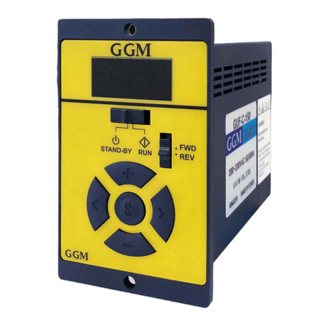
  9. GGM GUD Series User manual

GGM GUD Series User manual

www.ggm.co.kr
OPERATION MANUAL
GUD SERIES
SPEED CONTROL UNI T
■ Headquarters / 1st Factory : 22, Gyeongin-ro 3beon-gil, Bucheon-si, Gyeonggi-do, Republic of Korea
Tel:(032)664-7790 Fax:(032)611-7791
■ Attached research institute / No. 2 factory : 180, Oksan-ro, Bucheon-si, Gyeonggi-do, Republic of Korea
Tel:(032)684-7791 Fax:(032)683-5059
GGM Co., Ltd.
DIGITAL
GLOBAL GEARED MOTOR
- 2 -
Thank you for purchasing this GGM product.
Please do not use this product until you have read this user's guide
thoroughly and familiarized yourself with the knowledge, safety
information and precautions related to the product that it contains.
After reading this user's guide, keep it at hand to use as a reference
whenever it is needed.
1. Safety precautions
Please observe the following safety precautions in your use and
operation of the product. Failure to observe the precautions may
result in electric shock, injury or fire. The following precautions are
very important and need to be observed at all times.
Warning
Ignoring the following warnings and
instructions on the handling of the product
may result in death or serious injury.
• Do not use the product near explosive materials, flammable gases,
 corrosive materials, combustible materials, or in places where it may be
 splashed by water. This may cause fire, electric shock or injury.
• Do not forcibly bend, pull or insert the motor lead wire.
 This may cause fire or electric shock.
• Do not move, install, connect or check the product while it is
 connected to an electric current. Carry out the work only after cutting   
 off the power supply. Failure to do so may cause an electric shock.
• Have a qualified person with relevant knowledge install, connect,
 operate, control and check the product for failure. Failure to do so may  
 cause fire, electric shock or injury.
• Within 1 minute after cutting off the power supply, do not touch the  
 output terminal. This may cause an electric shock.
• Cut off the power supply when the power failure protection device or  
 overheating protection device (THERMAL PROTECTOR) operates. Failure to 
 do so may cause injury due to sudden re-operation of the product.
• Install the speed controller in the housing. Ground the protection       
 ground terminal when it is installed. Failure to do so may cause electric  
 shock or injury.
• Observe the rated voltage for the AC power supply to the speed
 controller. Failure to do so may cause a fire or damage to the product.
• Do not disassemble or modify the motor or the speed controller.
 This may cause an electric shock or injury.
- 3 -
Caution
Ignoring the following warnings and
instructions on the handling of the product
may result in injury or property damage.
• Do not use the motor or the speed controller beyond its specifications. 
 Doing so may cause injury or damage to the product.
• Do not operate the product with wet hands. Doing so may cause
 an electric shock.
• Do not hold or carry the motor’s lead wire.
 Doing so may cause disconnection and injury.
• Do not use the product for up and down operation. Doing so may
 cause injury or damage to the product.
• Use the motor only when the surface temperature of the motor is
 90℃ or below.
• Disconnect the power supply if you do not intend to use the product  
 for an extended period of time.
• Do not touch the product with your hand or any other body part while 
 operating the product or immediately after stopping its operation.
 As the surface of the motor is very hot, there is a risk of burn.
• If an abnormality occurs, cut off the power supply immediately to
 stop the operation.
• The controller has no protection device. Install an over-current
 protection device, earth leakage circuit breaker or overheating protection
 device for safety.
• If the product is operated in parallel with a device controlled in
 a thyristor for a high-capacity electric furnace or welding machine,
 the  product may malfunction. Wire separately using a separate power
 supply circuit.
• The product can be used at ambient temperatures between -10℃ and
 40℃ and humidity less than 85%. Avoid exposure to direct sunlight,
 moisture or grease, and when using the product in such places,
 use the cover.
• Do not use the product in a place where static electricity occurs
 frequently.
• Dispose of this product as industrial waste.
• If you need to repair the product, contact us or the place where you
 purchased the product.
• Do not modify the product arbitrarily. Arbitrary product modification by 
 the customer will void the warranty.
- 4 -
2. Confirmation when the product is handed over
- Confirm that the delivered product is the product you ordered.
- If a different product is installed, there is a risk of injury or fire.
- Contact a nearby retail store if there is a shortage compared to the
 number of the products you ordered or if a damaged product is
 delivered.
 1) CONTROLLER          
 2) Extension cable (0.5m)
 3) User’s Guide (this book)
 4) Option (extension cable)
---------------- 1EA
Item
name
Extension
cable
Length
KE-05
0.5m
KE-10
1m
KE-15
1.5m
KE-20
2m
If the controller is far away from the
motor, refer to the optional
specifications detailed in the table
above. Extension up to 2 m is possible
using one extension cable.
Do not extend more than 2.5m,
as degradation of the motor’s
properties may occur.
3. Specifications
Model name
Characteristics
GUD-U-□
GUD-C-□
Rated voltage and power
frequency
 Single-phase
100V~115V
50/60Hz
Single-phase
220V~240V
50/60Hz
Range of service voltage
±10% (in comparison to the
rated voltage)
Applied motor output
6 ~ 180W
Speed control range
50Hz : 90~1430rpm
60Hz : 90~1730rpm
Speed setting
Increase or decrease by 10
due to input setting
Service temperature range
-10~40℃
Preservation temperature range
-20~60℃
Service humidity range
Less than 85% (place with no
dew condensation)
Protection level
IP20
A number indicating the output of the motor is displayed where the □ is placed in the
model name.
- 5 -
4. CONTROLLER CODING SYSTEM
G
U
D
-
C
-
60
C : Single Phase
220V 50/60Hz
230V 50/60Hz
240V 50/60Hz
U : Single Phase
110V 50/60Hz
115V 50/60Hz
6 : 6W
15 : 15W
25 : 25W
40 : 40W
60 : 60W
90 : 90W
120:120W
180:180W
GGM
Co.,LTD.
Unit
Type
Digital
Type
5. Outside view of the product
- 6 -
6. Characteristics of the product
① Indicates the current rotation speed (r/min).
② The motor speed can be controlled simply by connecting
 the motor and the control unit using the dedicated connector, and 
 connecting the AC terminal to the power source.
③ You can use the CW/CCW key at the front side and the external 
 input port at the rear side to change the direction between forward 
 and backward.
④ Multi-level speed control can be achieved using the input port.
 (4 levels)
⑤ You can control the speed simply by using the front switch.
 - Range of variable speed -
 50Hz : 90 ~ 1430 r/min, 60Hz : 90~1730 r/min
⑥ Various operation modes are available through the parameter setting.
 - Reduction gear ratio, acceleration/deceleration time, Lock, brake
 function, speed change unit
 ⑦ The external volume can be used.
7. Applied motor
K
9
I
G
40
N
C
--
SU
6: 6W
15: 15W
25: 25W
40: 40W
60: 60W
90: 90W
120:120W
180:180W
F :
Cooling
Fan
N :
Non
Fan
J : 1Ø100V
50/60Hz
U : 1Ø110V
60Hz
L : 1Ø200V
50/60Hz
C : 1Ø220V
50/60Hz
1Ø230V
50/60Hz
D : 1Ø240V
50Hz
SU :
SPEED
CONTROL
UNIT
TYPE
SP :
SPEED
CONTROL
PLUG IN
TYPE
I: Induction
R: Reversible
GGM
Co.,
LTD.
6: □60
7: □70
8: □80
9: □90
S: Straight
G: Pinion
General
P: Pinion
Powerful
- The motor and the speed controller are packaged separately,
so confirm that the speed controller can be used for the applicable
motor.
- 7 -
8. Names and functions of each part
- 8 -
9. Wiring method
 9-1 Power and motor wiring
▶ Connect the motor
connector to the motor
connector terminal at the back
of the controller.
▶ Connect the AC power to
power supply terminals
No. ① and No. ②.
SW1 contact capacity
AC 125V or 250V 5A or higher
▶ Connects grounding to No. ③.
9-2 Forward and backward signal wiring
▶You can operate forward
 and backward motor rotation
 by connecting to I/O input
 terminals No. ①, No. ② and
 No. ③.
SW2
SW3
Motor shaft rotation
ON
OFF
Rotate in the CW direction
OFF
ON
Rotate in the CCW direction
OFF
OFF
Stop
※ I/O input takes precedence
over the RUN/STOP key at
the front.
※ LEAD WIRE connection method
※ Lead wire specifications
  - AWG 26~20 (0.14~0.5 ㎟)
  - Length of the stripped sheath : 8mm
▶ Insert the lead wire while depressing
   the orange-colored button using
   a screwdriver.
- 9 -
9-3 Multi-level speed wiring method
▶You can set the speed in 4 levels
by connecting to I/O input terminals
No. ③, No. ④ and No. ⑤.
SW4
SW5
MOTOR rotation
speed
OFF
OFF
Set speed at the front
ON
OFF
SPD 1 set speed
OFF
ON
SPD 2 set speed
ON
ON
SPD 3 set speed
9-4 External variable resistance (speed change) wiring method
▶ You can change the speed
 by connecting variable
 resistance to  I/O input
 terminals No. ⑥, No. ⑦
 and No. ⑧.
 (20KΩ 1/4W characteristics )
9-5 Brake wiring method (Speed control brake motor)
▶ Connect the electromagnetic
brake line to I/O input terminal
No. ⑨ and power supply terminal
No. ①.
▶ Enable the use of the brake in
the parameters.
[OFF => ON] (Refer to Page 14)
▶ In the event of a Motor RUN
signal, the power will be supplied
to the brake, and in the event of
a Motor STOP signal, the power   
 supplied to the brake will be cut
off.
- 10 -
① Supplying the AC power (Connect the AC power to the
 power supply terminals No. ① and No. ②)
The indicator lamp illuminates.
(Rotation speed)
② Controlling the operation key (operation)
When you press the RUN/STOP key, the
motor will start rotating at the set
speed.
[RUN/STOP indicator lamp illuminates green]
③ Rotation speed setting
Press the ▲ key to increase the speed
Press the ▼ key to decrease the speed
Display of rotation speed / When the
 power is supplied again, the motor will
rotate at the new rotation speed.
④ Changing the direction of rotation
When you press the CW/CCW key while the
motor is rotating in a CW direction, the
rotational direction of the motor will change
to CCW.
When you press the CW/CCW key while the
motor is rotating in a CCW direction, the
rotational direction of the motor will change
to CW.
[If you change the direction while the motor
is operating, the direction will not change
immediately. The direction changes after the
motor decelerates and stops.]
⑤ Controlling the operation key (stop)
When you press the RUN/STOP key
while the motor is operating, the motor
will stop.
[RUN/STOP indicator lamp illuminates red]
10. Operation and parameter setting sequence
10-1 Operation sequence
- 11 -
 10-2 Parameters
Display
unit
Function
Range
Default
value
Note
RATE
Reduction
gear
ratio
1~
999
1.0
Reduction gear ratio setting
REAL RPM =
Motor rotation speed / Reduction gear
ratio
S-ON
Accele
ration
time
0~15
0.0
Mode set to accelerate the
rotation of the motor slowly
(increments of 0.1 second)
SOFF
Decele
ration
time
0~15
0.0
Mode set to decelerate the
rotation of the motor slowly
(increments of 0.1 second)
LOCK
Lock
Function
YES
NO
NO
Mode set to prevent the change
of the set operation condition by
locking setting keys other than    
RUN/STOP key
 YES: Lock, NO: Unlock
DGT
Speed
change
unit
1,5,
10
10
When setting the
acceleration/deceleration speed, set
a speed change unit.
(If set to 10, the speed increases
 by 10)
SPD1
Set
speed
1
90~
1730
500
Multi-level operation speed SPD1
setting
(Operates when the I/O inputs
 ③-④ are connected)
SPD2
Set
speed
2
90~
1730
1000
Multi-level operation speed SPD2
setting
(Operates when the I/O inputs
 ③-⑤ are connected)
SPD3
Set
speed
3
90~
1730
1500
Multi-level operation speed SPD3
setting
(Operates when the I/O inputs
 ③-④-⑤ are connected)
BRK
Brake
functio
n
YES
NO
NO
Set whether or not to use the
electromagnetic brake
 YES: Use the brake
 NO: Do not use the brake
- 12 -
① Supplying AC power
The indicator lamp illuminates.
(Rotation speed)
② Entering Parameter mode (Press and hold)
Press and hold the CW/CCW key
(for 3 seconds or longer) to enter
 Parameter mode.
③ Selecting a parameter (9 parameters)
Press the Arrow keys to select the
desired parameter.
The mode changes in the order of
RATE -> S-ON -> SOFF -> LOCK -> DGT
-> SPD1 -> SPD2 -> SPD3 -> BRK
④ Entering parameter data (press briefly)
Press CW/CCW briefly to enter the
selected parameter data. When you
press CW/CCW briefly after entering
data,the parameter selection mode will
be displayed.
⑤ Changing parameter data
Press the arrow keys to change the data
 value.
Set the desired data value.
⑥ Finishing parameter data change and entering Operation mode
(Press and hold)
When you press and hold the CW/CCW
key (for 3 seconds or longer), the
 changed value will be set and saved,
and the motor will enter Operation
mode.
Caution) If you press the CW/CCW key
briefly, the changed value will not be
saved.
※ To enter Operation mode after entering Parameter mode,
press and hold the [CW/CCW] key.
 10-3 Parameter setting sequence
- 13 -
① Supplying AC power
The indicator lamp illuminates.
(Rotation speed)
② Entering Parameter mode (Press and hold)
Press and hold the CW/CCW key
(for 3 seconds or longer) to enter
 Parameter mode.
③ Selecting a parameter
Press the arrow keys to select the RATE
parameter.
④ Entering RATE DATA (Press briefly)
Press the [CW/CCW] key briefly to enter 
 RATE parameter data
(When you press CW/CCW briefly after
 entering RATE parameter data, the
parameter selection mode will be
displayed.)
⑤ Changing parameter data
Press the arrow keys to set the
reduction gear ratio
- Default value: 1 (Setting range: 1-999)
- Change the set reduction gear ratio
from 1 to 10.
⑥ Finishing parameter data change and entering Operation mode
(Press and hold)
When you press and hold the CW/CCW
 key (for 3 seconds or longer), the
changed value will be set and saved,
 and the motor will enter Operation
mode.
The displayed speed will change to the reducer output speed due
to the setting of 1/10 of the reduction gear ratio.
(90~1730 rpm => 9~173 rpm)
 10-4 Setting method if using the reduction gear ratio
 (ex. 1/10 of the reduction gear ratio)
- 14 -
① Supplying AC power
The indicator lamp illuminates.
(Rotation speed)
② Entering Parameter mode (Press and hold))
Press and hold the CW/CCW key
(for 3 seconds or longer) to enter
 Parameter mode.
③ Selecting a parameter
Press the arrow keys to select the
BRK parameter.
④ Entering BRK DATA (Press briefly)
Press the [CW/CCW] key briefly to enter
BRK parameter data.
(When you press CW/CCW briefly after
 entering BRK parameter data,
the parameter selection mode will be
 displayed.)
⑤ Changing parameter data
Press the arrow keys to set whether or
not to use the brake.
- Default value : NO ( Do not use brake )
- To use the brake, change NO => YES
⑥ Finishing parameter data change and entering Operation mode
(Press and hold)
When you press and hold the CW/CCW
 key (for 3 seconds or longer),
the changed value will be set and saved,
 and the motor will enter Operation
mode.
10-5 Setting method if using the electromagnetic brake
- 15 -
11. Installation method (Panel process drawing)
 - Drill a hole in the installation panel as shown in the figure below.
Assemble the controller body and the front cover, and fix them using
M4 screws and nuts.
(Use an installation panel with a thickness of 2mm or less)
12. Potential causes of failure, and countermeasures
Problem
Checkpoints
 The value is not displayed
 on the display unit when
 power is supplied.
• Check the connection of
 AC power supply.
 The motor does not rotate.
• Check whether the motor is
 connected correctly.
• Check whether the RUN key
 illuminates green and I/O connection
 is established properly.
• Check whether the motor is
 overloaded.
 The motor rotates, but
 the speed cannot be
 changed.
• Check for abnormalities in the
TG signal of the motor, or for
incorrect wiring.
 The motor does not run
 immediately.
• Check whether an excessively long
 acceleration time has been set.
 The speed cannot be changed.
• Cancel the lock setting.
 There is abnormality or
 excessive vibration during
 motor operation.
• Check whether the motor is affected
 by an external noise.
• Confirm that the combination of the
 motor and the speed controller is the same.
- 16 -
※ Contact the retail store where you purchased the product or our Factory 2
if you have any product inquiries or customer service requests.
Leader of geared motor GGM CO.,LTD.
http://www.ggm.co.kr
Headquarters / 1st Factory
22, Gyeongin-ro 3beon-gil, Bucheon-si,
Gyeonggi-do, Republic of Korea
TEL : 82-32-664-7790 FAX : 82-32-611-7791
Attached research institute / No. 2Factory
180, Oksan-ro, Bucheon-si,
Gyeonggi-do, Republic of Korea
TEL : 82-32-684-7791 FAX : 82-32-683-5059

This manual suits for next models

2

Other GGM Control Unit manuals

GGM GUF Series User manual

GGM

GGM GUF Series User manual

GGM GUS-U Series User manual

GGM

GGM GUS-U Series User manual

GGM GUS Series User manual

GGM

GGM GUS Series User manual

GGM GSA Series User manual

GGM

GGM GSA Series User manual

Popular Control Unit manuals by other brands

ProSoft Technology inRax MVI69-101M user manual

ProSoft Technology

ProSoft Technology inRax MVI69-101M user manual

oventrop AQH operating instructions

oventrop

oventrop AQH operating instructions

RIB NOVA ACG8046 manual

RIB

RIB NOVA ACG8046 manual

Homematic IP 153413A0 Mounting instruction and operating manual

Homematic IP

Homematic IP 153413A0 Mounting instruction and operating manual

Ponar WEH22 Series Operation manual

Ponar

Ponar WEH22 Series Operation manual

Panasonic AG-GPS15P installation guide

Panasonic

Panasonic AG-GPS15P installation guide

Siemens XC1003-A Operation

Siemens

Siemens XC1003-A Operation

SCHUCK U Installation & operation manual

SCHUCK

SCHUCK U Installation & operation manual

Elsner IMSG 230 installation instructions

Elsner

Elsner IMSG 230 installation instructions

Nice Mindy A100F Instructions and warnings for the fitter

Nice

Nice Mindy A100F Instructions and warnings for the fitter

Samsung SPC-6000 Specifications

Samsung

Samsung SPC-6000 Specifications

Exhausto OJ GreenZone instructions

Exhausto

Exhausto OJ GreenZone instructions

Digitrax UT1 manual

Digitrax

Digitrax UT1 manual

Abocom WM5208 user manual

Abocom

Abocom WM5208 user manual

System Sensor M502M Installation and maintenance instructions

System Sensor

System Sensor M502M Installation and maintenance instructions

Vaillant sensoNET VR 921 installation instructions

Vaillant

Vaillant sensoNET VR 921 installation instructions

Megmeet MC5000 Series User quick reference manual

Megmeet

Megmeet MC5000 Series User quick reference manual

actionair neo Installation and commissioning

actionair

actionair neo Installation and commissioning

manuals.online logo
manuals.online logoBrands
  • About & Mission
  • Contact us
  • Privacy Policy
  • Terms and Conditions

Copyright 2025 Manuals.Online. All Rights Reserved.