SPEED CONTROL UNIT
External operation switch
[This is used for starting or stopping
external operation. / When it is set to
ON, the motor operates. when it is set
to OFF, the motor stops]
Motor connector block
[Connects the motor connector]
Motor terminal block
[This is used to connect the lead wire
to the motor]
Power terminal block
[Connects the AC power supply]
Protective ground terminal
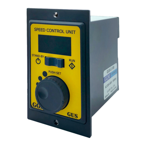
Display unit
[Displays the rotation speed and parameters]
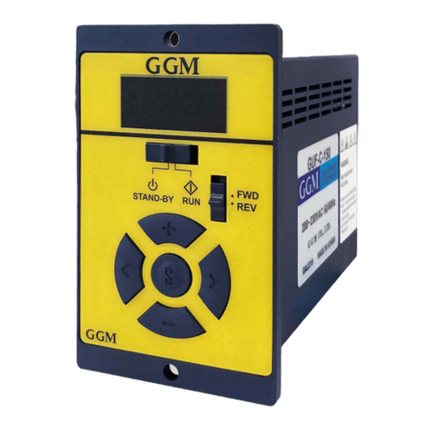
Operation switch
[When you movethe operation switch to
RUN, the motor rotates. when you move the
operation switch to STAND-BY, the motor
stops.]
Dial
[Changes the rotation speed or parameters]
▶ Forward operation wiring ▶ Reverse operation wiring
1) Connect the motor connector
2) Connect the ②COM and
③CW terminals.
3) Connect the AC power to the
⑥ and ⑦ terminals.
▶ Two-way operation wiring ▶ External operation wiring
1) Connect the motor connector.
2) Install the power supply switch
(SW1) and the forward and
reserve rotation exchange switch
(SW2) and change the rotation
direction.
Instantaneous forward and
reverse rotation are unavailable.
Turn off the power supply switch
(SW1), and when the motor has
stopped completely, replace the
switch (SW2) to change the
direction.
Caution) If you replace the switch
(SW2) to change the direction
when the power supply switch
(SW1) is ON, it may damage the
controller.
1) Connect the motor connector.
2) Connect the ②COM and
③CW terminals. (CW operation)
Refer to the CCW operation and
two-way operation wiring.
3) Connect the AC power to
terminals⑥ and ⑦.
4) Install the external operation
switch (SW1).
When you move the front
operation switch to STAND-BY
and turn on the external operation
switch (SW1), the motor operates.
When you turn off the external
operation switch (SW1), the
motor stops.
AC 125V or 250V 5A or higher
AC 125V or 250V 5A or higher
After wiring, operate the product as follows.
① AC power supplied
The indication turns on. (Rotation speed)
② Control of operation switch (operation)
When you movethe operation switch to RUN, the
motor will rotate.
③ Setting the rotation speed
When you turn the dial, the rotation speed will change.
The rotation speed changed by the speed to rotate
the dial.
Display of rotation speed
When the power is supplied again, the motor will rotate
at the new rotation speed.
④ Control of operation switch (stop)
When you movethe operation switch to STAND-BY, the
motor will stop.
H-5
S-ON
SOFF
LOCK
Set the reduction gear ratio
(can be adjusted in increments of 0.1)
REAL RPM = Motor rotation speed / reduction gear ratio
Mode set to accelerate the rotation of the motor slowly
(set in increments of0.1 seconds)
Mode set to decelerate the rotation of the motor slowly
(set in increments of0.1 seconds)
Mode set to prevent anychange inthe set operation condition
by locking setting keysother than RUN and STAND-BY keys.
YES: Enable locking mode NO: Disable locking mode
RATE
Deceleration
time
Lock
function
Parameter setting sequence
① Supply AC power
The indication turns on. (Rotation speed)
② Entering the parameter mode
Press and hold the dial (PUSH-SET) for 3 seconds to enter
the parameter mode.
③ Selection of a parameter
Press the dial (PUSH-SET) to enter the selected parameter
data.
When you press the dial (PUSH-SET) after entering the
data, the parameter selection mode will be displayed.
④ Entering the parameter data
When you press and hold the dial (PUSH-SET) for 2
seconds, the changed value will be set and you will enter
the operation mode.
Short press
When you rotate the dial, the data value will change.
Set the desired data value.
⑤ Changing the parameter data
⑥ Finishing the parameter data change and entering the operation mode
Press and hold (2 seconds)
Turn the dial and select the desired parameter (4 parameters)
Modes can be selectedin the order of
RATE -> S-ON -> SOFF -> LOCK
(reduction gear ratio) -> (acceleration time) -> (deceleration time) -> (locking)
To enter operation mode after entering the parameter mode, press and hold the
dial (PUSH-SET) for 2 seconds.
Names and functions
of each part
1) Connect the motor connector
2) Connect the ②COM and
①CCW terminals.
3) Connect the AC power to the
⑥ and ⑦ terminals.
Operation sequence
Parameters
Default
value
Reduction
gear ratio
Acceleration
time
Press and hold (3 seconds)
MOTOR CONNECTOR MOTOR CONNECTOR
MOTOR CONNECTOR MOTOR CONNECTOR
decreas in g increas ing


