Giant Leap Rocketry Talon 4 User manual

INSTRUCTION MANUAL
Talon 4
GIANT LEAP ROCKETRY, LLC
Copyright 2006 - 2017 Giant Leap Rocketry, LLC
2831 SW Cornelius Pass Road
Hillsboro, Oregon 97123
!

1
THE TALON 4 IS A FANTASTIC - LARGE ROCKET BUILD!!!
PLEASE BE AWARE THAT THE FIRESTORM CAN (DEPENDING ON THE MOTER CHOSEN) GO OVER 8,000
FEET; THEREFORE A TRACKING SYSTEM IS RECOMMENDED FOR A SUCCESSFUL RECOVERY.
At Giant Leap Rocketry, LLC hope you enjoy this rocket. The TALON 4 is carefully engineered to make this rocket
high performance on the one hand, yet efficient to build on the other. We recommend that you take your time, learn
and enjoy. The TALON 4 series is another in a long line of high quality kits from Giant Leap Rocketry, LLC.
The TALON 4 is the first of our nearly complete kits. At this level of rocket building and design most
rocketeers like some choice in the recovery components of the rocket. The TALON 4 comes with every-
thing you need to build the rocket. All you need to provide is the parachute. In the parts list you will
find recommended parachutes Should you need assistance do not hesitate to reach out to our fantastic
GLR team.
!
TALON 4
We provide more details to help with your rocketry education

The TALON 4 comes with a 54mm motor
mount so that it can be flown on powerful J and
K motors. These will propel the TALON 4 to
extremely high altitudes. With the optional
SLIMLINE 54/38mm adapter, you can fly this
rocket to more moderate altitudes on lower im-
pulse H and I motors. Be certain your center of
gravity (CG) is at least 8” or more forward of
the center of pressure (CP), with 9” or more be-
ing ideal. All measurements need to be done
with a “full-up” rocket (with a loaded motor, re-
covery components and any electronics). Re-
member, during launch, the recovery hardware
may shift aft, thus shifting the CG to an unsta-
ble condition. Be sure to check your rocket care-
fully before flying.
This is critically important or the
rocket will not be stable in flight.
For example, if your rocket is 1.5” in diameter,
then the CG should be at least 3” forward of the
center of pressure. We provide you with the CP
distance from the tip of the nosecone. As long
the design remains the same as provided by
GLR, the CP won’t change; but, if you modify
the length of the rocket you will need to deter-
mine the CP again for yourself. The CG de-
pends on the weight distribution, which can
change depending on your motor choice or
other items that change the weight of the
rocket. You can find the distance of the CG by
balancing the rocket on your finger. If the CG
is too far back, add nose weight. All measure-
ments must be done with a “launch ready”
rocket. This means your rocket is loaded with a
motor, recovery components and any electron-
ics or other accessories you plan to use during
flight. Remember, during launch, the recovery
hardware may shift aft, thus shifting the CG to
an unstable condition. Be sure to allow for this
before flying by loading your recovery compo-
nents aft in order to properly check CG.
Note: Heavier motors shift the CG aft, requir-
ing you to add nose weight. Be sure to check
the CG location prior to launch!!
2
TALON 4 is a no compromise duel deploy
rocket. This rocket is for the more experienced
flyer. You have chosen the best and most beau-
tiful 98mm rocket on the flight line!!!

Specifications:
Dry Wt. Mass (no motor load) 198 oz. (Please
allow for slight variation in weight due to differ-
ence in epoxies and paint thickness).
Length: 92”
Outside Diameter O.D. 4.02”
Inside Diameter I.D. 3.9 ”
CP= 65” aft from nosecone tip
CG should be less than 57” aft of nosecone tip
Motor Mount: 54mm (29&38 mm with optional
54/38 mm adapter)
Recommended 38mm motors: Requires the
optional SLIMLINE 54/38mm adapter
Aerotech: H123, H148, H242, I161, I357,
I300, I211, I285, I284, 1366, I435, J420, J350,
J570
Pro38: H153 I205, I285, J285, J330
Recommended 54mm motors:
J90, J180, J275, J315, J415, J135, J800, J540,
J800, K1100, K695, K550, K695, K700
Pro54: J295, K445, K570, K660
WARNING!!
Flying rockets is potentially dangerous, and
you or others can be injured and/or killed by
the usage of this product. Property damage can
also occur by the usage of this product. In us-
ing this product, you agree to comply strictly
with all safety codes of the Tripoli Rocketry As-
sociation and the National Association of Rock-
etry, as well as all local, State and Federal laws.
By using the product, you agree that Giant
Leap Rocketry, LLC, (also in this document
noted as GLR) it’s owners or employees will
not be held legally or financially responsible
for the correct or incorrect usage of this prod-
uct. If you do not agree with these statements,
return the kit in resalable condition to Giant
Leap Rocketry for a refund. By using this kit,
you agree that you have read, understand and
accept these conditions.
PLEASE READ THE SAFETY CODE AND
LIABILITY STATEMENTS AT THE END
OF THESE INSTRUCTIONS.
NOTE: THIS ROCKET IS NOT A TOY
BECAUSE OF THE ROCKETS SIZE AND
WEIGHT IT IS A SERIOUS VIOLATION
OF FEDERAL LAW TO FLY THIS
ROCKET ANYWHERE EXCEPT AT
LAUNCHES SANCTIONED BY THE TRIP-
OLI ROCKETRY ASSOCIATION OR THE
NATIONAL ASSOCIATION OF ROCK-
ETRY WHOSE ORGANIZERS HAVE SE-
CURED AN APPROPRIATE WAIVER
FROM THE FEDERAL AVIATION ADMIN-
ISTRATION. FAILURE TO DO SO CAN
RESULT IN SUBSTANTIAL FINES AND/
OR IMPRISONMENT. DO NOT EVEN
THINK OF FLYING THIS ROCKET ANY-
W H E R E E X C E P T AT C E RT I F I E D
LAUNCHES.
3

IF YOU HAVE ANY QUESTIONS OR ARE
UNCLEAR REGARDING THE ASSEM-
BLY OR USE OF THIS PRODUCT,
PLEASE CALL GIANT LEAP ROCK-
ETRY, LLC. YOU ARE TOTALLY RE-
SPONSIBLE FOR THE SAFE USAGE OF
THIS ROCKET. FOLLOW ALL PERTI-
NENT SAFETY CODES AND DIREC-
TIONS AT THE LAUNCH SITE. ALWAYS
WEAR EYE PROTECTION WHENEVER
LOADING EJECTION CHARGES OF
ANY TYPE AND KEEP SPECTATORS
AWAY. MAKE A CHECK LIST TO HELP
YOU PREPARE YOUR ROCKET PROP-
ERLY SO AS NOT TO OVERLOOK AN IM-
PORTANT STEP DURING THE EXCITE-
MENT AND STRESS OF PRE-FLIGHT
PREPARATION. IF YOU DO NOT FEEL
READY TO FLY THIS OR ANY OTHER
ROCKET DON’T. Take your time and do it
safely and correctly. REMEMBER, THE
FUTURE OF THIS HOBBY ALONG WITH
THE SAFETY OF THOSE AROUND YOU
IS IN YOUR HANDS.
PARTS LIST:
TALON 4 BODY PARTS
1- 98mm Nose Cone
1- 98mm Tailcone -Slotted
1- 98mm 36” Fiberglass Airframe Slotted
-Tagged to Match the Talecone
1- 98mm 24” Fiberglass Airframe
1- 54mm 36” Phenolic Motor Mount Tube
1- 98mm/54mm Centering Rings
3- Small 0.093” Fiberglass Pre-cut Fins
3- Large 0.093” Fiberglass Pre-cut Fins
1- 54mm GLR Slimline Retainer Set
1- 98mm R Rail Guide Pair
6 - 4” Frackets
6 - 8” Frackets
AV-Bay Parts:
1- 98mm 8” Fiberglass Coupler
2- 98mm Bulkhead (Pre-Drilled)
2-98mm Coupler Bulkhead (Pre-Drilled)
1- 6.75” X 3.25” Fiberglass Sled
2- 4” X ¼” Plastic Tubes
2- 1 X ¼” Eye Bolt
4

2- 10” All-Thread
2- ¼” Lock Nut
6- ¼” Nut
2- ¼” Wing Nut
10- Washers
Recovery Mount:
2- 98mm/54mm Centering Ring
(Pre-Drilled)
1- ¼” Eye Bolt
2- Washers
1- Lock Nut
Recover Components:
4- ⅛” Quick Link
2- 1,000 lb Swivels
2- 15’ ¼” GLR Kevlar Double Loop Shockcord
2- 2” x ½” GLR Kevlar Tube Cord
2- Medium Sized GLR Kevlar Parachute Protec-
tor
1- 24” Wooden Dowel
Online Assembly Instruction Booklet
Optional Parts to Consider:
72” GLR TAC1 Parachute
24” GLR TAC1 Parachute
4-way Reduced Momentum Parachute Slider as
seen in photograph. Free with the Purchase of a
72” GLR TAC1 Parachute
98mm GLR Slimline Threaded Retainer
Retainer Adapter 54mm/38mm
1- 12” Motor Mount Tube
1- 1” Spacer
Retainer Adapter 38mm/29mm
1- 12” Motor Mount Tube
5

1- 1” Spacer
Disposable Supplies
Needed by the Builder
to Assemble This Kit:
30 Minute Epoxy or GLR Aeropoxy!
!(Can Be Ordered Separately From GLR)
Mixing Cups and Mixing Sticks!
!(Can Be Ordered Separately From GLR)
J.B. Weld
!(Can Be Ordered Separately From GLR)
Glass-Mirco-Spheres
Masking Tape
Tape Measure
Sharp Pencil
#250 Sandpaper
Paper Towels
Gloves ! ! !
!(Can Be Ordered Separately From GLR)
Rubbing Alcohol
Drill with a 1/8” and 1/32” drill bit
NOTE: you MUST use high-quality epoxy and
JB Weld with this kit. Other types of adhesives
are not suitable and will make the rocket unsafe
for flight.
ASSEMBLY
A. Building the Motor tube Assembly
Note: “forward” means the front of the rocket,
towardthe nosecone, and “aft” is the rear of the
rocket.
1. Test fit the GLR Slimline Motor Retainer
on the Aft end of the 54mm motor tube. Be
sure that the GLR Slimline Motor Retainer
goes onto the motor tube and seats completely.
If the GLR Slimline Motor Retainer is seated
completely, you will not have any of the epoxy
bonding rings of the GLR Slimline Motor Re-
tainer exposed and the motor tube will rest on
the the built-in shoulder stop of the GLR Slim-
line Motor Retainer. Sand the motor tube
slightly, if necessary, but just enough for a
snug-tight fit. If you have a 54mm casing (Ae-
rotech or Pro54), test fit it by placing the casing
in the motor tube and inserting the retaining
ring. Be sure the spacing of all components is
correct before proceeding to the next step that
involves epoxy.
2 Place the GLR Slimline Motor Retainer
on the motor tube and draw with a pencil, a line
6

at the forward end of the GLR Slimline Motor
Retainer and then remove the retainer from the
motor tube.
3. Mix some J.B.Weld (and only J.B Weld -
do not use ep-
oxy!) and apply
it to the aft end
of the motor
tube, to the pen-
cil mark of the
m o t o r t u b e .
Then, install the
GLR Slimline Motor Retainer onto the motor
tube. Turn the GLR Slimline Motor Retainer
while you are installing it in order to spread the
J.B. Weld. Be sure that you only apply the
J.B. Weld to the motor tube and NOT to the
inside of the GLR Slimline Motor Retainer.
This is important because if you apply J.B.
Weld to the GLR Slimline Motor Retainer and
then try and slip it onto the motor tube, excess
J.B. Weld will seep into the snap ring area of
the GLR Slimline Motor Retainer, making it im-
possible to insert a motor correctly. It is also a
g o o d i d e a t o
place the snap
ring into the slot
and tape off the
exposed slot of
the GLR Slim-
line Motor Re-
tainer while seat-
ing the GLR Slimline Motor Retainer onto the
motor tube as this will prevent excess J.B. Weld
from seeping into the snap ring area. MAKE
SURE THE GLR SLIMLINE MOTOR RE-
TAINER IS SEATED ALL THE WAY ONTO
THE MOTOR TUBE. Remove the snap ring,
clean up any excess epoxy and let it set up com-
pletely.
4. There are two centering rings that make
up the Forward Centering Ring assembly. Both
will have a
hole drilled in
them for the
eye-bolt assem-
bly, which will
secure part of
your recovery
system. Mix a
p o r t i o n o f
GLR Aeropoxy and place on the the surface of
both of the
Forward Cen-
tering rings.
Place the eye-
bolt assembly
and tighten
the nut com-
pletely. There
is a washer on both sides of the centering ring.
(It is advisable to use gloves when using epox-
ies). Place a clamp opposite of the ring to in-
sure that the rings are perfectly together and
7

symmetrical. This is critical or the rings will
not enter the airframe correctly, nor will they go
onto the motor tube correctly. Let the GLR
Aeropoxy set up completely.
Now you will place the Forward Centering
Ring onto the motor tube. Measure from the
forward end of the motor tube 2” and place a
mark. Using a piece of paper wrapped around
the motor tube, centered on the mark that you
made at 2”, draw a line around the motor tube.
Place multiple layers of masking tape on the
line that was drawn. This will act as a stop
when you seat your Forward Centering Ring.
Place a generous amount of JB Weld around the
motor tube the thickness of the Forward Center-
ing Ring . Do not use epoxy for this union.
This centering ring will take a tremendous
amount of force
when the recovery
system deploys and
JB Weld is signifi-
cantly stronger.
Slide the Forward
Ce nt er in g Ri ng
ont o the mot or
tube, twisting as
you seat it. You
will notice that the
eye-bolt is close to
the forward end of
the tube and that is correct. Make sure that the
Forward Centering Ring is level and parallel to
the forward opening of the motor tube. Allow
the JB weld to cure completely.
5. Now that the Forward Centering Ring is
fully cured it is time to place the Middle Center-
ing Ring. This Centering Ring is placed ex-
actly like the Forward Centering Ring except
you will place the Middle Centering Ring 15”
8

from the Aft opening of the Airframe or the
GLR Slimline Retainer previously welded to
the motor tube. Make sure that the Middle
Centering Ring is level and parallel to the open-
ing of the motor tube. Allow the JB weld to
cure completely.
6. It is now very important to place a thick fil-
let on the Forward and Aft ends of both of the
Centering Rings to secure the Centering Rings
to the Airframe. Fillets can be created using a
variety of materials, Giant Leap Rocketry, LLC
recommends using GLR Aeropoxy and GLR
Glass-Micro-Spheres. Mix a generous amount
of Aeropoxy. Add to this mixture GLR Glass-
Micro-Spheres until you obtain a thick peanut
buttery consistency. The ratio is typically 2
parts GLR Glass-Micro-Spheres to 1 part GLR
Aeropoxy. More important that the ratio how-
ever, is the thick peanut buttery consistency.
Create a large fillet between the motor tube and
the Centering Rings by placing a liberal amount
of material on both the Forward and Aft sur-
faces of the Centering Rings and allow them to
completely set up.
B. Securing the Motor Tube to the Airframe
and Talecone
Warning: Once everything is set up and cured
your motor tube is ready to be inserted and
glued to the airframe and tailcone. This is the
most difficult step in the entire build and it is
important that you take great care in following
the directions exactly.
1. Line up the airframe and the tailcone. Each
airframe and tailcone are paired and cut to-
gether. You will notice as you put the tailcone
and airframe together there is a number or letter
9

on each piece. The number or letter should be
the same. You will also see a large X at the in-
terface of the two pieces. This is the position in
which each set of fin slots were prepared and
you must maintain this position if your fins are
to line up true to one another.
You will first place the motor tube into the fiber-
glass airframe. Dry fit the motor tube several
times into the airframe. It should slide
smoothly but snugly in and out and line up with
the end of the tailcone. You may need to care-
fully remove a small amount of the internal di-
ameter of the end of the tailcone if need.
Please be careful, the motor tube is meant to be
snug-fit. Once you feel that it is correct, place
the tailcone onto the motor tube and connect
the tailcone to the airframe with the motor tube
in place. Once you can line the X up on the air-
frame and tailcone you are ready to insert the
motor tube for real.
Since the air-
frame is a
high quality
fiberglass
you will be
able to see
through the
fiberglass
and see the
C e n t e r i n g
Rings. On
the outside
of the airframe make a mark with a pencil
where the Centering Rings are. Disassemble
the motor tube from the tailcone and airframe.
Warning: If you have large hands and you can-
not comfortably fit your hand into the 4” air-
frame you will want to attach your quick link
and GLR Kevlar Shock Cord to the eye-bolt at
this point. This is not however recommended
because it is very difficult to keep the GLR
Aeropoxy from contaminating your GLR Kev-
lar Shock Cord. So if you can wait until later to
attach the quick link, that is best.
Using the included wooden dowel, you will
now fabricate a custom glue stick. You can use
just the dowel if you would like; however you
may find it easier to keep
your dowel clean if you take
this additional step. Tape a
wooden frozen treat stick to
your wooden dowel. This
gives a nice edge to smear
the GLR Aeropoxy and
keeps your dowel clean.
Place a piece of tape on the
dowel so that the tip of your
stick corresponds to the line
drawn on the airframe indi-
cating where the centering
rings are located. You will
have two measurements on
this one dowel because you
w i l l b e p l a c i n g G L R
10

Aeropoxy inside the air-
frame in two locations: the
luting position of the For-
ward and Middle Center-
ing Rings. Mix a very gen-
erous portion of GLR
Aeropoxy. Place the
GLR Aeropoxy on the in-
side of the airframe at the
level that you marked for
the Forward Centering
Ring. Once you have a good thick coating of
GLR Aeropoxy circumferentially at this loca-
tion, insert the motor tube about half way into
the airframe. When it is inserted thus, place
GLR Aeropoxy on the inside of the airframe at
the level where you marked the Middle Center-
ing Ring. Once you have a good thick coating
of GLR Aeropoxy circumferentially at this loca-
tion insert the motor tube the rest of the way un-
til the motor tube is inserted completely and the
Centering Rings line up with the lines that you
drew on the outside of the airframe. Place the
tailcone onto the motor tube to make sure that
the GLR Slimline Motor Retainer lines up per-
fectly with the Aft opening of the tailcone. Ad-
just the motor tube in or out as needed to insure
that the GLR Slimline Motor Retainer lines up
perfectly with the Aft opening of the tailcone.
DO NOT EPOXY THE TAILCONE TO THE
AIRFRAME AT THIS TIME. Let the GLR
Aeropoxy cure completely.
2. Sand the inside of the slotted airframe and
the corresponding area of the tailcone. Place
some masking tape on the inside of the GLR
Slimline Motor Retainer or stuff it with paper
towel - this will prevent epoxy from entering
this critical area. Apply a generous amount of
GLR Aeropoxy to the tailcone. DO NOT IN-
SERT THE TAILCONE INTO THE AIR-
FRAME JUST YET. Also mix a generous por-
tion of JB Weld and place it on the outside of
the GLR Slimline Motor Retainer. Carefully
guide the tailcone over the motor tube and into
the airframe. MAKE SURE THAT THE X
LINES UP ON THE TAILCONE AND THE
AIRFRAME. Take care to remove the paper
towel or masking tape from the GLR Slimline
Motor Retainer and clean the GLR Slimline Mo-
tor Retainer with a solvent to insure that no JB
Weld has contaminated the internal surface of
the GLR Slimline Motor Retainer.
3. Set the rocket upright resting on the tail-
cone. Mix some GLR Aeropoxy and add some
GLR Glass Micro-spheres. In this mix we are
not going for the typical peanut butter consis-
tency, but rather we want a thick but flowable
mixture. When you are happy with the consis-
tency, you will pour the GLR Aeropoxy / GLR
Glass Micro-spheres mixture into the forward
opening of the slotted airframe. The idea is to
pour in enough epoxy to cover the entire For-
ward Centering Ring. Be careful not to put in
11

so much that you can not connect the D-ring to
the eye-bolt later on.
C. Attaching the Fins
We at Giant Leap Rocketry believe you are go-
ing to love this next step. We have innovated a
device that adds strength to the fin / airframe
connection and incredible ease to the fin mount-
ing process. No longer will you need to use
“fin mounting templates” to place your fins.
GLR has provide in this kit our exclusive 4”
GLR Frackets.
1. Place the forward (large) fin into the for-
ward slot in the airframe. All fins are inserted
with the rounded or curved portion of the fin
forward. Insure that the fin is all the way for-
ward in the slot. Once you have successfully
preformed your dry fit, remove the fin. Mix
some GLR Aeropoxy and place it on the edge
of the fin. Insert the fin into the slot until the
fin makes contact with the motor tube and trans-
fers the GLR Aeropoxy to the motor tube. You
will want to repeat the process 3-5 times to in-
sure that you have good amount of GLR
Aeropoxy contacting the fin / motor tube inter-
face. In addition you can drip some GLR
Aeropoxy through the slot.
2. Now you are ready to attach the GLR Frack-
ets to the airframe and fin. The Frackets are op-
tional but allow increased rigidity and strength
to the large fins. Take two 8” GLR Fracket and
place on the airframe “sandwiching” the fin.
On the forward fins, the GLR Fracket should be
placed between 2” and 3” from the forward
edge of the fin; on the aft fins the forward por-
tion of both GLR Frackets should line up
evenly with the forward tip of the fin. In both
cases insure that the curved portion of the GLR
12

Fracket is on the airframe and the flat portion is
against the fin. As you press the GLR Fracket
firmly against the airframe and fin, you will no-
tice the fin will straighten up and true itself to
it’s 90 degree, correct position. With a pencil,
outline the GLR Fracket on both the airframe
and fin. Sand these areas to insure a strong
bond of the JB Weld. You should also sand the
bonding surface of each of the GLR Frackets.
Mix some JB Weld and place on both planes of
the bonding surface of the GLR Frackets and in
the area of the airframe that you marked for the
GLR Fracket. Once satisfied, place the fin in
the slot and place both GLR Frackets in place
on either side of the fin. Remove any excess
JB Weld with a solvent and a paper towel and
secure the GLR Fracket in place with clamps
until fully cured.
3. On the aft fins you will repeat the above
steps with this one modification: the forward
portion of both GLR Frackets should line up
evenly with the forward tip of the fin. The
bond to the fiberglass is much greater than the
bond to the plastic tailcone, so take advantage
of all of the airframe that you have.
4. Repeat this step with all remaining fins. For
added strength and security, once the JB Weld
is set you can drill two holes in each GLR
Fracket about ¾” from the end and drive a bolt
through and secure the bolt, using a lock
washer and nut. Should you choose to drill
through the GLR Fracket on the wing that is at-
tached to the airframe or tailcone you will have
to use a small wood screw to attach it. Make
sure the hole is small enough so that the wood
screw is slightly difficult to insert and make
sure the wood screw is not so long as to enter
and damage the motor tube.
5. You now will need to create a fillet to transi-
tion your fin to the airframe. As you can see
there is a gap around and behind the fin. As de-
scribed earlier, fillets can be created using a va-
riety of materials, Giant Leap Rocketry, LLC
recommends using Aeropoxy and GLR Glass-
Micro-Spheres. Mix a generous amount of
13

Aeropoxy. Add to this mixture GLR Glass-
MicroMicro-Spheres until you obtain a thick
peanut buttery consistency. The ratio is typi-
cally 2 parts GLR Glass-Micro-Spheres to 1
part Aeropoxy. More important that the ratio
however, is the thick peanut buttery consis-
tency. Create a fillet between the airframe and
the fin, completely, forward to aft. Using a
gloved finger smooth the fillet to a clean transi-
tion from airframe to the fin. We also advise
you to create a fillet circumferentially around
the GLR Frackets. This will streamline area
and create less drag. Later you can sand any ir-
regularities you may have. The GLR Glass-
Micro-Spheres add strength to the epoxy and
can be sanded to a smooth surface. It is not un-
common for the fillet to sag or droop over time
as it sets up; so you may have to repeat this
step. Take great care with your fillets, the bet-
ter and smoother you place the fillets, the less
work is required later when you sand them in
preparation for painting.
D. Building the Upper Section and Avionic
Bay (GLR E-Bay)
1. Test fit 8” fiberglass coupler (avionics bay
body) into the two airframes and sand if neces-
sary for a moderate slip fit.
2. Sand the two internal portions of the bulk-
head sets so that they go into the airframes eas-
ily, with absolutely no resistance. They should
practically fall through the airframe. Make a
pencil mark about 4” from one end of the cou-
pler. That should leave about 4” on the other
end. Wrap a piece of paper around the coupler
with the edges lining up at the
mark you just made, this will cre-
ate a straight edge that you can
then draw a line circumferentially
around the coupler.
3. Prepare both eye-bolts by
screwing one ¼” nut onto the eye-
14

bolt and follow it on with a washer. On one
bulkhead, insert an eyebolt through the middle
hole, and secure it with a washer and nut on the
backside. Make sure the ¼” holes line up with
each other. Also, make sure the nut is tight on
the eye bolt and secure it with a small drop of
Aeropoxy. Do the
same with the other
bulkhead.
4. Secure the two
pieces of all-thread
in the two ¼” holes
using a locknut and
washer on the eye-
bolt side, and a nut
and washer on the
backside, as is seen
in the photo. The
all-thread, with the
lock nut on it will stick out about ¾” from the
bulkhead. Add a ⅛” quick-lock ring to the eye
bolt and attach one section of the GLR Kevlar®
Shock Cord to the quick lock. Set these pieces
aside and we will get back to adhering the GLR
E-Bay to the Forward airframe.
5. Apply Aeropoxy to the outer surface of the
coupler. Spread the Aeropoxy up to the 4”
mark on the coupler. ( It is advisable not to
spread the Aeropoxy all the way to the edge of
the coupler but leave the ½” to ¼” of the cou-
pler free of Aeropoxy. This will be valuable
when you attempt to
place the forward
bulkhead onto the
coupler. If you allow
the GLR Aeropoxy
to get on the edge of
the coupler when
you attempt to place
the bulkhead the
bulkhead will not fit
flat on the coupler.
Insert the coupler
into the Aft end of
the forward section
o f t h e a i r f r a m e .
Again, Do NOT ap-
ply Aeropoxy to the
inside of the air-
frame and make
sure that any Aeropoxy that is on the edge of
the GLR E-Bay coupler is cleaned off so that
the bulkheads will fit flush against the cou-
pler. Hold upright or vertical until GLR
Aeropoxy sets completely. Do not turn upside
down or some Aeropoxy will seep into the up-
per airframe. Tape the coupler in place if neces-
sary to prevent it from dropping out while the
15

GLR Aeropoxy is setting. Let it set (upright)
before handling it further. Using alcohol and a
paper towel, clean up any excess GLR
Aeropoxy. Do not leave any extra GLR
Aeropoxy on the GLR E-Bay or on the Aft
edge of the airframe, or it will not seat prop-
erly between the two body tubes. Let set un-
til completely cured.
6. At this point it is time to build the electron-
ics sled. There are a couple of ways to accom-
plish this step. I will share my preferred
method. Place the tubing on the all-thread and
center the sled under the tubing. Mark the sled
on either side of the tub-
ings with a Sharpie Mark-
er®. With a power drill,
drill four holes through
the fiberglass sled table.
Make sure that the holes
are just the size of the
zip-ties you will be us-
ing. Fasten each end of
the tube to the sled table
with zip-ties. An alterna-
tive method is to GLR
Aeropoxy the tube to the
sled or even combine the
two techniques for dou-
ble redundancy. If you use GLR Aeropoxy, you
must sand the tubing slightly to insure a proper
adhesion. The sled is ready to accept your
electronics (sold separately).
7. Now we will insert
the bulkhead attached to the
all-thread through the for-
ward opening in the forward
airframe. The bulkhead
must slide easily, and with-
out any resistance. Sand the
bulkhead as needed to
achieve this smooth-sliding
fit. Allow it to drop down
until it flush with the top of
the GLR E-Bay coupler.
8. We will now
pretend that you
have attached your
electronics to the
sled. Take the sled
and slide it onto the
all-thread that is
sticking out of the for-
ward airframe. Line up
the unused bulkhead
with the all-thread and
secure it with the wing
nut and washer. Make
sure that the bulkhead
lines up smoothly with
the end of the GLR E-
Bay.
16

9. Attach a ⅛” quick-link to the remaining
exposed eyebolt on the GLR E-Bay.
C. Recovery System
1. We will begin with the Drogue recovery
system that will be located in the Aft Airframe.
You have been provided two small GLR Kev-
lar® Socks. Normally these GLR Kevlar®
Socks are used instead of masking tape to cover
and protect nylon shock cords from the burn of
the ejection charge; however, we have provided
you with GLR Kevlar® Shock Cords in keep-
ing with our commitment to provide the best
quality products and to insure the continued
and long use of your rocket. The purpose of
these small pieces of GLR Kevlar® Sock is to
prevent potential damage to the GLR Kevlar®
shock cords during deployment of the recovery
systems. When the Drogue and Main recovery
systems deploy the GLR Kevlar® Shock Cords
will rub against the sharp edge of the fiberglass
airframe. Though the risk is small, we do not
want the GLR Kevlar® Shock Cords to sepa-
rate and fail due to the rubbing of the GLR Kev-
lar® Shock Cord against the airframe, this GLR
Kevlar® Sock will reduce the risk of that hap-
pening.
2. To install the GLR Kevlar® Sock first
pinch open the GLR Kevlar® Sock and push
the forward loop of the GLR Kevlar® Shock
Cord through the opening and slide it all the
way down to the Forward
opening of the Aft section .
Attach the GLR Shock Cord
to the d-ring that you placed
on the eyebolt that is at-
tached to the Forward Cen-
tering Ring of the motor
tube. With one hand pull
tight on the GLR Kevlar®
Shock Cord and with the
other hand slid the GLR
Kevlar® Sock until is at its
half way-point lying on the
edge of the airframe, secure
it with making tape and/or
Aeropoxy.
3. GLR pro-
vides a high
quality GLR
Kevlar® Para-
chute Heat
Shield to pro-
tect your para-
chute from the
heat generated
that occurs as a
17

result of the ejection charge deploying your re-
covery system when your rocket reaches apo-
gee. We also provide a second GLR Kevlar®
Parachute Heat Shield to protect the Main re-
covery system during the second deployment.
Slide the first GLR Kevlar® Parachute Heat
Shield onto the free end of the GLR Kevlar®
Shock Cord that is attached to the eye-bolt that
is attached to the Forward Centering Ring in-
side the Aft airframe. Let the GLR Kevlar®
Parachute Heat Shield slide freely around. The
GLR Kevlar® Parachute Heat Shield never gets
anchored permanently to the line. Do not se-
cure the GLR Kevlar® Parachute Heat Shield
to the GLR Kevlar® Shock Cord; just let the
GLR Kevlar® Parachute Heat Shield slide
freely. Attach the free end of the GLR Kevlar®
Shock Cord to the exposed eyebolt that is at-
tached to the GLR E-Bay
3. Attach the eye bolt to the Aft end of the
GLR Olgive Nosecone as shown in the photo
and attach a quick link bolt to the eye bolt.
4. Now we will connect the eyebolt of the
forward end of the GLR E-Bay / forward body
tube and the GLR Olgive Nosecone. You will
connect the pieces of the forward section in the
same order as you did with the Aft section.
Again, begin by sliding the GLR Kevlar® Sock
Cord onto the GLR Kevlar® Shock Cord and
secure it at the edge of the forward airframe
with masking tape or GLR Aeropoxy. Slide the
second GLR Kevlar® Parachute Heat Shield
onto the GLR Kevlar® Shock Cord. Again, the
GLR Kevlar® Parachute Heat Shield will slide
freely on the GLR Kevlar® Shock Cord. At-
tach the forward loop of the GLR Kevlar®
Shock Cord to the quick connect bolt that is at-
tached to the GLR Olgive Nosecone and
tighten. Your rocket should now look like the
photo minus the parachutes. We will address
the parachutes now.
5. The parachutes recommended by GLR,
come pre-sewn to the swivels. Giant Leap
Rocketry, LLC Recommends a high quality,
large and strong parachute like the 72” GLR
TAC1 Parachute for your main deployment and
18

the 24” GLR TAC 1 Parachute for your drogue
deployment. These parachutes are made to the
most stringent standards. They are a high qual-
ity parachute for high-end applications. We
think it's the strongest and most stable chute in
the industry.
The TAC 1 is Tear-resistant - All seams are rein-
forced with nylon webbing.
The TAC 1 is Strong - 1/2" mil spec nylon
(1400 lbs test) all around the canopy.
The TAC 1 is Lightweight - 1.1 oz silicone-
coated low-porosity ripstop nylon.
The TAC 1 has a No Tangle Design - only four
suspension lines! The TAC1 comes with 1500#
test swivel for tangle-free descents.
It doesn't get any stronger.
3. At this point we will assume that you have
acquired your parachutes and we will now de-
scribe how to install
them. Attach the 24”
GLR TAC 1 Parachute
to the GLR Kevlar®
Shock Cord as follows.
At about 10 feet from
the forward end of the
Aft body tube, pinch
t h e G L R K e v l a r ®
Shock Cord and slide
t h e G L R K e v l a r ®
Shock Cord through the open end of the swivel
that is attached to the
GLR TAC 1 parachute,
form a loop and wrap
that loop around the
GLR TAC 1 parachute
and then tighten the
knot that is formed
around the swivel. Re-
move the Main (72”)
TAC 1 parachute from
its poly bags and hold it by the swivel. Attach
the 4-way Reduced Momentum Parachute
Slider (Optional or Free with the Purchase of
the GLR 72” TAC1) to the shroud lines of the
GLR 72” TAC 1 parachute. The GLR Reduced
Momentum Parachute Slider comes with 4
“keyring” style connectors. Each of these ring
connectors are attached to the shroud lines of
the parachute. The purpose of the GLR Re-
duced Momentum Parachute Slider is to slow
the deployment of the Main parachute by not
allowing the shroud lines to completely expand
19
Table of contents
Other Giant Leap Rocketry Toy manuals

Giant Leap Rocketry
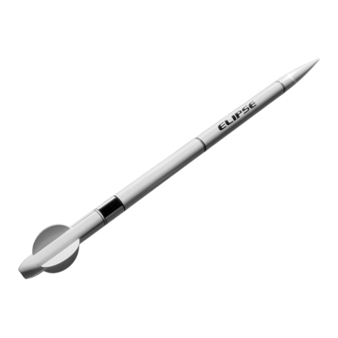
Giant Leap Rocketry Elipse User manual

Giant Leap Rocketry
Giant Leap Rocketry T-BOLT User manual

Giant Leap Rocketry
Giant Leap Rocketry TALON 6 User manual

Giant Leap Rocketry
Giant Leap Rocketry Liberty 2 User manual

Giant Leap Rocketry
Giant Leap Rocketry Talon 2 User manual

Giant Leap Rocketry
Giant Leap Rocketry Firestorm User manual

Giant Leap Rocketry
Giant Leap Rocketry T-BOLT User manual