Giant Leap Rocketry T-BOLT User manual

INSTRUCTION MANUAL
T-BOLT
GIANT LEAP ROCKETRY, LLC
Copyright 2006 - 2017 Giant Leap Rocketry, LLC
2831 SW Cornelius Pass Road
Hillsboro, Oregon 97123

T-BOLT 38mm
1
Thank-you and congratulations on pur-
chasing this beautiful high powered
rocket from Giant Leap Rocketry.
-The GLR Team-
THE T-BOLT IS THE PERFECT LEVEL 1 or LEVEL 2 ROCKET!!!
PLEASE BE AWARE THAT THE T-BOLT CAN (DEPENDING ON THE MOTER CHOSEN) GO OVER 6000
FEET; THEREFORE A TRACKING SYSTEM IS RECOMMENDED FOR A SUCCESSFUL RECOVERY.
We at Giant Leap Rocketry, LLC hope you enjoy this rocket. The T-BOLT is carefully engineered to make this
rocket high performance on the one hand, yet efficient to build on the other. We recommend that you take your time,
learn and enjoy. The T-BOLT series is another in a long line of high quality kits from Giant Leap Rocketry, LLC.

T-BOLT...The Perfect Level 1 or Level 2
We provide more details to help with your rocketry education
The T-BOLT is a perfect rocket for a level 1
launch. The T-BOLT is a 38mm minimum di-
ameter rocket. This means that the airframe is
the motor mount tube as well. It is adaptable
down to 29mm motor using the optional 29-
38mm Slimline adapter (ordered separately
From GLR). The T-BOLT can be flown on a
variety of motors to extremely high altitudes.
Be certain your center of gravity (CG) is at
least 1.5 body diameters or more forward of the
center of pressure (CP) when the rocket is fully
loaded and ready for flight!
This is critically important or the
rocket will not be stable in flight.
For example, if your rocket is 1.5” in diameter,
then the CG should be at least 3” forward of the
center of pressure. We provide you with the CP
distance from the tip of the nosecone. As long
2
T-BOLT shown with the optional high performance FinCan and
optional Nozzle-Shaped Motor Retainer

the design remains the same as provided by
GLR, the CP won’t change; but, if you modify
the length of the rocket you will need to deter-
mine the CP again for yourself. The CG de-
pends on the weight distribution, which can
change depending on your motor choice or
other items that change the weight of the
rocket. You can find the distance of the CG by
balancing the rocket on your finger. If the CG
is too far back, add nose weight. All measure-
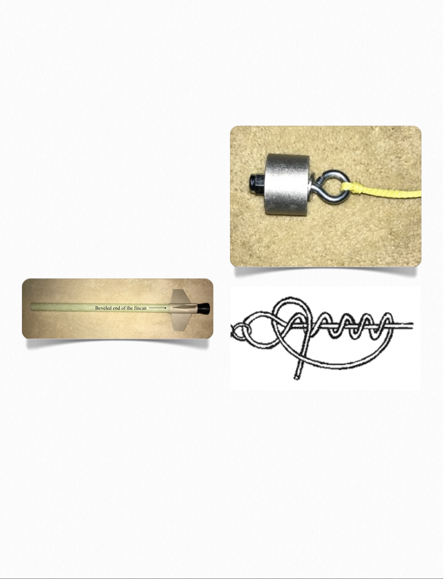
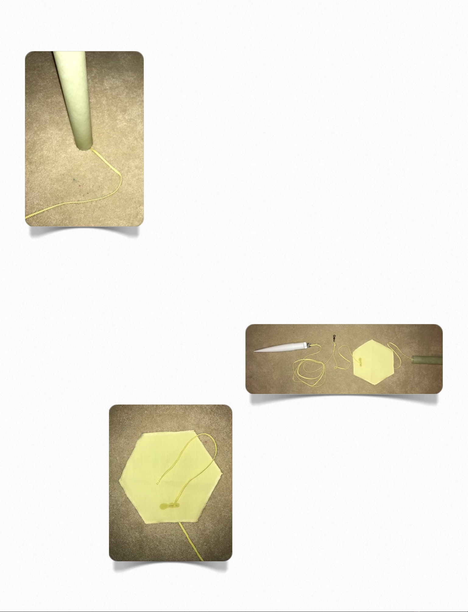
ments must be done with a “launch ready”
rocket. This means your rocket is loaded with a
motor, recovery components and any electron-
ics or other accessories you plan to use during
flight. Remember, during launch, the recovery
hardware may shift aft, thus shifting the CG to
an unstable condition. Be sure to allow for this
before flying by loading your recovery compo-
nents aft in order to properly check CG.
Note: Heavier motors shift the CG aft, requir-
ing you to add nose weight. Be sure to check
the CG location prior to launch!!
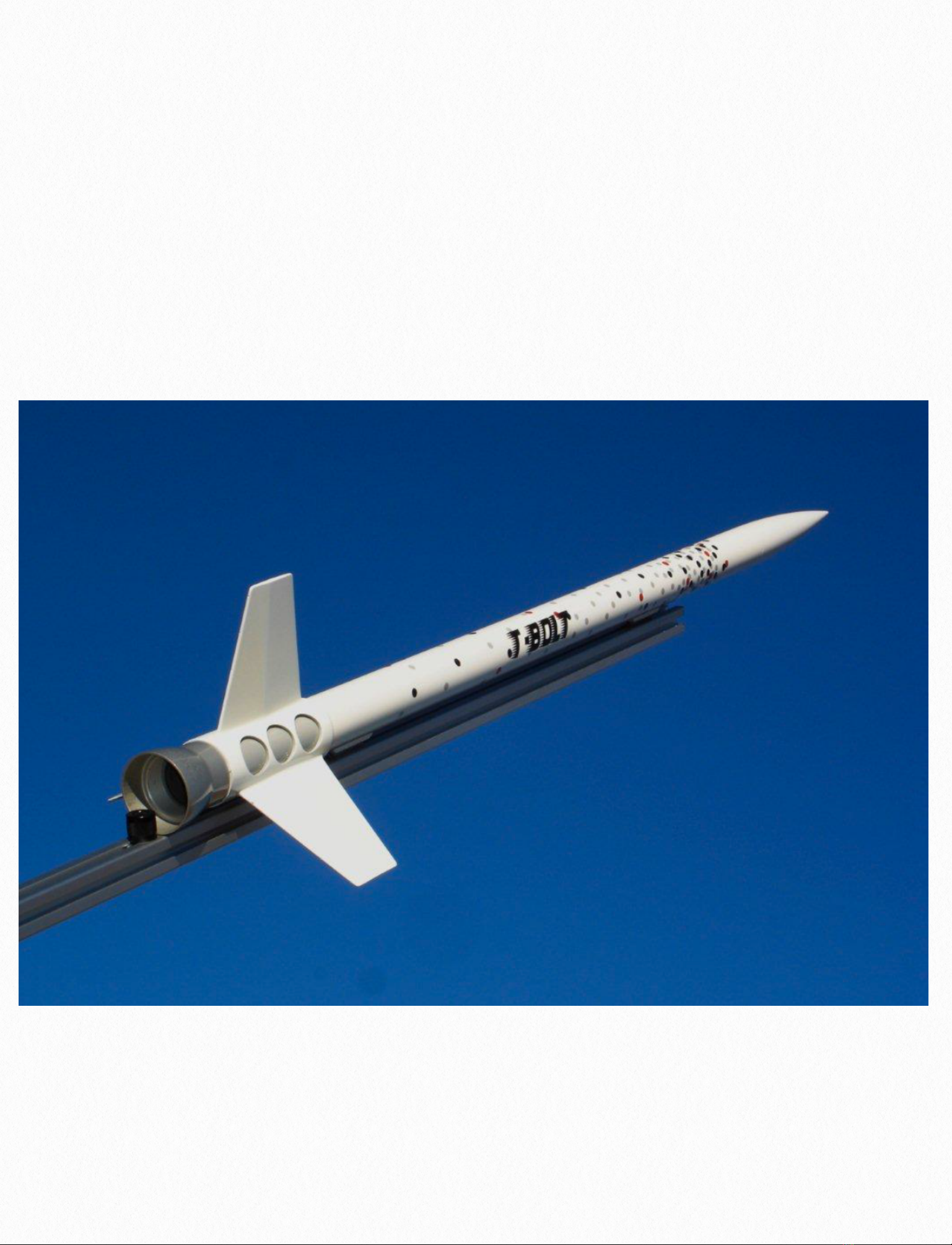
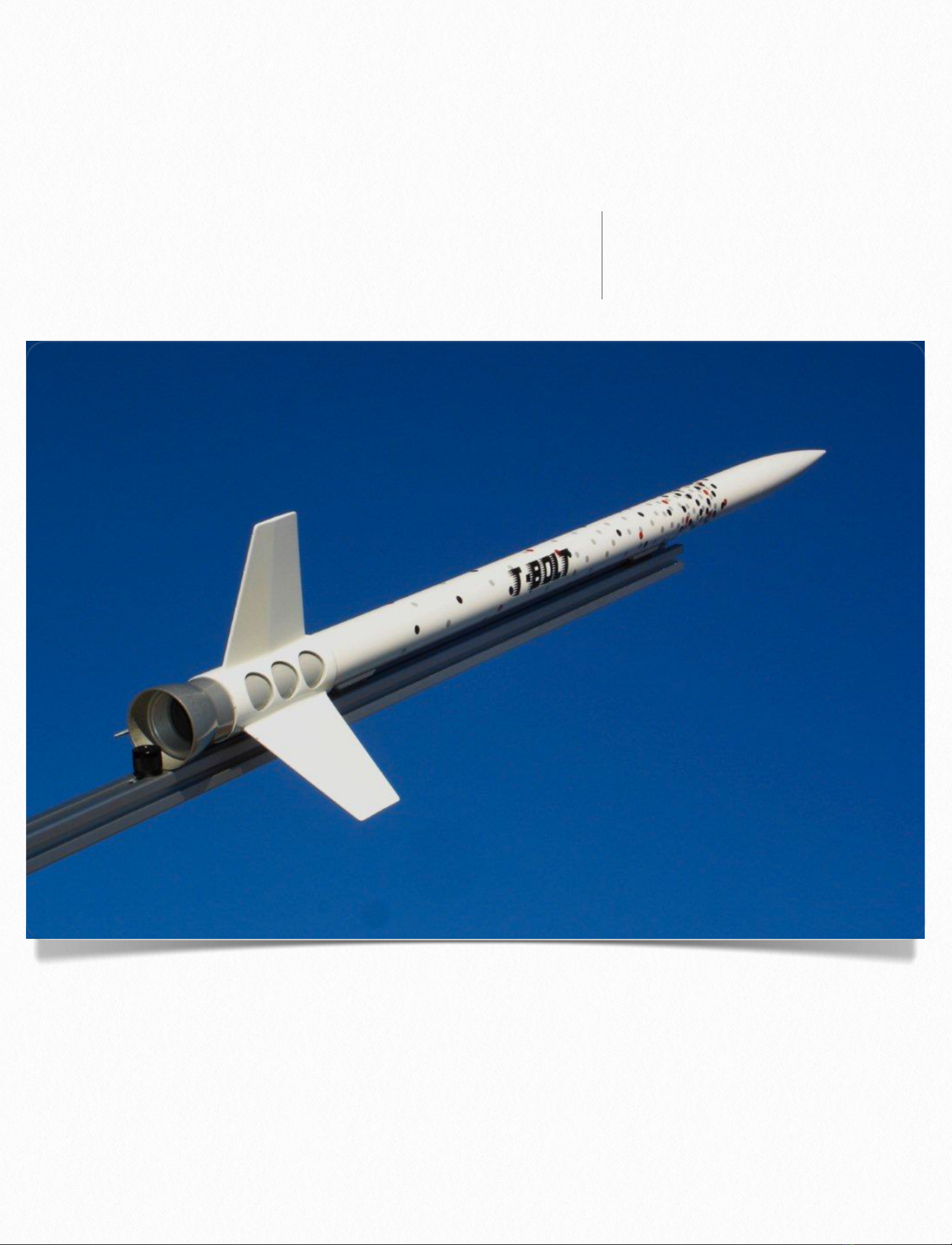
Specifications:
Dry Wt. Mass (no motor load) 38.15 oz.
Length: 42 ½” (with Nozzle retainer the length
is 43 ⅛")
Outside Diameter O.D. 1.65”
Inside Diameter I.D. 1.36”
CP=36.7” aft from nosecone tip
CG should be less than 33” aft of nosecone tip
Motor Mount: 38mm (29mm with adapter)
Parachute: 30”
Recommended motors (motors in italics require
38 to 29mm adapter):
Aerotech 29mm motors: H128, H165, H180,
H210
Aerotech 38mm Motors: I161, I357, I300, I211,
I284, I366, I435, J420, J350
WARNING!!
Flying rockets is potentially dangerous, and
you or others can be injured and/or killed by
the usage of this product. Property damage can
also occur by the usage of this product. In us-
ing this product, you agree to comply strictly
with all safety codes of the Tripoli Rocketry As-
sociation and the National Association of Rock-
etry, as well as all local, State and Federal laws.
By using the product, you agree that Giant
Leap Rocketry, LLC, (also in this document
noted as GLR) it’s owners or employees will
not be held legally or financially responsible
for the correct or incorrect usage of this prod-
uct. If you do not agree with these statements,
return the kit in resalable condition to Giant
Leap Rocketry for a refund. By using this kit,
you agree that you have read, understand and
accept these conditions.
3

PLEASE READ THE SAFETY CODE AND
LIABILITY STATEMENTS AT THE END
OF THESE INSTRUCTIONS.
NOTE: THIS ROCKET IS NOT A TOY
BECAUSE OF THE ROCKETS SIZE AND
WEIGHT IT IS A SERIOUS VIOLATION
OF FEDERAL LAW TO FLY THIS
ROCKET ANYWHERE EXCEPT AT
LAUNCHES SANCTIONED BY THE TRIP-
OLI ROCKETRY ASSOCIATION OR THE
NATIONAL ASSOCIATION OF ROCK-
ETRY WHOSE ORGANIZERS HAVE SE-
CURED AN APPROPRIATE WAIVER
FROM THE FEDERAL AVIATION ADMIN-
ISTRATION. FAILURE TO DO SO CAN
RESULT IN SUBSTANTIAL FINES AND/
OR IMPRISONMENT. DO NOT EVEN
THINK OF FLYING THIS ROCKET ANY-
W H E R E E X C E P T AT C E RT I F I E D
LAUNCHES.
IF YOU HAVE ANY QUESTIONS OR ARE
UNCLEAR REGARDING THE ASSEM-
BLY OR USE OF THIS PRODUCT,
PLEASE CALL GIANT LEAP ROCK-
ETRY, LLC. YOU ARE TOTALLY RE-
SPONSIBLE FOR THE SAFE USAGE OF
THEIS ROCKET. FOLLOW ALL PERTI-
NENT SAFETY CODES AND DIREC-
TIONS AT THE LAUNCH SITE. ALWAYS
WEAR EYE PROTECTION WHENEVER
LOADING EJECTION CHARGES OF
ANY TYPE AND KEEP SPECTATORS
AWAY. MAKE A CHECK LIST TO HELP
YOU PREPARE YOUR ROCKET PROP-
ERLY SO AS NO TO OVERLOOK AN IM-
PORTANT STEP DURING THE EXCITE-
MENT AND STRESS OF PRE-FLIGHT
PREPARATION. IF YOU DO NOT FEEL
READY TO FLY THIS OR ANY OTHER
ROCKET DON’T. Take your time and do it
safely and correctly. REMEMBER, THE
FUTURE OF THIS HOBBY ALONG WITH
THE SAFETY OF THOSE AROUND YOU
IS IN YOUR HANDS.
PARTS LIST:
One-1.5" x 33” Filament-Wound Fiberglass
One-1.5" Pinnacle Nosecone
One- Eye Bolt For the Nosecone
One- 38mm Slimline Retainer Set
One- 38mm Acme FinCan
One- Pack of 2 38mm Acme Rail Guides
One- Twelve foot ¼” Kevlar® Shock Cord
One- KEVLAR® Parachute Heat Protector Pad
One- 30” Parachute
One- Hard Point shock cord attachment
4

One- Glue stick dowel rod 18" long
One- Assembly Instruction
STYLE OPTIONS:
A Slimline Nozzle retainer (Pictured on Cover)
and GLR Rail Guide Stand offs are available as
an option.
Disposable Supplies
Needed by the Builder
to Assemble This Kit:
5, 15 or 30 Minute Epoxy or Aeropoxy!
!(Can Be Ordered Separately From GLR)
Mixing Cups and Mixing Sticks!
!(Can Be Ordered Separately From GLR)
J.B. Weld! ! !
!(Can Be Ordered Separately From GLR)
Masking Tape
Tape Measure
Sharp Pencil
#250 Sandpaper
Paper Towels
Latex Gloves !! !
!(Can Be Ordered Separately From GLR)
Rubbing Alcohol
NOTE: you MUST use high-quality epoxy and
JB Weld with this kit. Other types of adhesives
are not suitable and will make the rocket unsafe
for flight. You may prefer a slower setting ep-
oxy (30 min.) if you are a novice builder, as this
will allow more time to assemble the rocket.
ASSEMBLY
1. On the 33" long 38mm airframe, with a pen-
cil mark one end "Forward” and the other end
"Aft” and sand the outside of the airframe up
six inches from the Aft end.
2. Using JB Weld, attach the GLR Slimline
motor retainer to the AFT end of the motor
tube. You MUST use JB Weld because it is
rated for high temperature use, whereas regu-
lar epoxy is not. You could lose the motor if
you do not use JB-Weld. Allow to fully cure
before moving to the next step. If during
your trial fitting of the motor retainer, the mo
tor retainer seems a bit too loose, simply place
a SMALL amount of tape on the aft end of the
airframe at distances of about 120 degrees from
5

each other overlapping the end of the tube.
This will snug up the fit and allow a proper ad-
hesion. Once the motor retainer is in place re-
move any tape that is exposed.
3. With a pencil, mark the tapered end of the
GLR FinCan "FORWARD" and the other end
"AFT". FinCan is short for "fin canister".
Slide the FinCan onto the FORWARD end of
the airframe, making sure that the AFT end of
the FinCan goes on first. The words "FOR-
WARD" and "AFT" on the airframe and Fin-
Can should match direction when the FinCan is
in place.
4. Do not slide it all the way on. Instead, tem-
porarily tape the FinCan to the airframe so that
the AFT end of the FinCan is about 6” above
the GLR Slimline Motor retainer.
5. Apply Aeropoxy to the area that will be cov-
ered by the FinCan.
6. Before the epoxy cures, remove the tape
from the GLR FinCan and slide it the rest of the
way onto the airframe until the AFT end of the
FinCan butts up against the GLR Slimline mo-
tor retainer. Once in position, clean up any ep-
oxy that oozed out the AFT end with alcohol
and paper towels. Set upright on your work sur-
face (resting on the retainer) and allow to fully
cure.
7. Next, identify the GLR Hard-point Recov-
ery System Anchor. Place the eyebolt through
the center of the device, and tighten the nut.
There should be a washer on both sides of the
Hard-point. Secure one end of the Kevlar®
shock cord to the eye bolt by tying the above
fisherman’s clinch knot. A secure attachment is
necessary at this stage because this mount will
no longer be accessible once it is inserted into
6

the airframe. Dap a small drop of epoxy on the
knot to prevent it from unraveling. Because Gi-
ant Leap Rocketry provides heat-resistant Kev-
lar® shock cord in this kit, rather than nylon,
there is no need to wrap the shock cord with
masking tape.
INSERTING THE HARD-POINT INTO
THE AIRFRAME IS TRICKY. READ
THESE NEXT STEPS THOROUGHLY TO
UNDERSTAND THE PROCEDURE BE-
FORE ATTEMPTING TO COMPLETE IT.
8. Once the GLR FinCan and GLR Hard-point
are prepared and the epoxy is fully cured, you
must insert the Hard-point into the airframe as
follows: You are provided a glue stick dowel.
Do not snap it or otherwise alter the length be-
cause it serves as a guide. Mix a small amount
of JB Weld (do not use epoxy). Measure the
dowel and make a mark on the dowel at 16”.
With one hand, hold the airframe horizontally
(i.e., flat, not upright). With the other hand, dip
the glue stick into the mixed epoxy and insert
the glue stick UNTIL THE LINE ON THE
END YOU ARE HOLDING IS FLUSH WITH
THE FORWARD END OF THE AIR-
FRAME (the end opposite to the fin can). Ap-
ply epoxy in a ring to the interior of the air-
frame. The ring of epoxy should coat the inter-
nal circumference of the airframe from the 16”
to the 14” mark from the forward end of the air-
frame.
It is important to avoid getting the JB Weld on
other areas inside the airframe, so do the best
you can. You will be able to clean up some
later. Repeat the procedure as necessary until
you have a full-solid ring of JB Weld inside the
airframe. Remove glue stick and clean off the
JB Weld from your glue stick.
Before the JB Weld cures within the airframe,
insert the GLR Hard-point through the FOR-
WARD end of the airframe, Hold the Kevlar®
shock cord and insert the Hard-point NUT
SIDE IN FIRST, making sure that the free end
of the shock cord points FORWARD, or away
from the fin can. Using the CLEAN glue stick,
push the Hard-point all the way down until the
mark you made on the glue stick is 1” from
the FORWARD end of the airframe. Once in
place, immediately take a moistened paper
towel with alcohol on the end of the glue stick
and swab out the inside of the airframe remov-
ing JB Weld where it should not be. AVO I D
MOVING THE JUST PLACED HARD-
POINT.
7

IMPORTANT:
Once the Hard-
point is in place,
hold the airframe
u p s i d e d o w n
with the FOR-
WARD end point-
ing to the ground
and the FinCan
(AFT end) up.
This prevents JB
Weld from drip-
ping down the
motor tube section of the airframe (which
would prevent the insertion of a motor casing).
It is also a good idea to check that JB Weld is
not running down the FORWARD end of the air-
frame as well. This could interfere with your re-
covery components. If JB Weld does drip for-
ward you can clean it as explained above. If
the Hard-point slides forward and is not sta-
ble in the airframe, place the airframe in a
more horizontal
position. Allow
the JB Weld to
fully cure.
9. GLR provides
a high quality
Kevlar® para-
chute heat shield
to protect your
parachute from
the heat generated that occurs as a result of the
ejection charge deploying your recovery system
when your rocket reaches apogee. Slide the
chute protector onto the free end of the shock
cord. Do not secure it to the cord; just let the
protector slide freely.
10. Slide the swivel on to the free end of the
shock cord - it will be used in step 14.
11. Screw the eyebolt into the base of the Pinna-
cle nose cone.
12. Tie the other end of the shock cord to that
eyebolt.
13. A dap of epoxy will prevent the knot from
unraveling.
14. Grab the swivel and tie a small loop into the
shock cord about 36” from the nosecone. A dap
of epoxy on the knot will help. This loop with
the swivel will be the parachute attachment
point. BE SURE THAT THE CHUTE PRO-
TECTOR IS BELOW OR AFT OF THE LOOP
(ON THE OTHER SIDE OF THE NO-
SECONE). The sequence is a follows: No-
secone, eyebolt, shock cord, loop with swivel,
8

shock cord, chute protector, shock cord and air-
frame. See photo above.
15. Carefully remove the parachute from that
poly bag and hold the parachute by the
shroud lines. Center or "even" the lines at
the apex held with your finger. Side the
shroud lines together through the free end
of the swivel and open the shroud lines
enough to allow the parachute to slide
through and knot down onto the swivel.
Vent Holes in Airframe - - IMPORTANT!
Because the air pressure is reduced at high alti-
tudes, you will need to relieve the internal pres-
sure in the recovery compartment; otherwise
the nosecone will pop off the airframe during
ascent. To avoid this, drill, opposite the rail
guides, one 3/32” hole about 13” back from the
tip of the nosecone, another at 21” from the tip
of the nosecone. These holes are absolutely nec-
essary for a safe flight. Do not make the holes
any larger or you will risk reducing the effec-
tiveness of the ejection charge.
RECOVERY SYSTEM PREPARATION
1. To prepare
the rocket for
flight, insert
most of the
s h o c k c o r d
into the air-
fr am e fir st .
Do this by cre-
ating accordion lengths of cord about 3-4" long,
then insert into the tube. Leave about 3-4 feet
of cord out.
2. Roll up the
p a r a c h u t e .
Then slide up
the protector
towards the
c h u t e . D o
NOT slide the
protector all the way to the chute, but instead
stop about 1 foot away. Then lay some shock
cord into the protector, then lay the chute in the
pad too.
3. Fold the
p r o t e c t o r
around the
9

chute like a burrito and insert into airframe.
You must position the heat pad so that it pro-
tects the chute from scorching. Should you find
the “burrito” to tight for the airframe, shake
some corn starch on the “burrito” and it should
slide much easier.
4. Slide the nosecone onto airframe. The no-
secone should be snug but not tight onto the air-
frame. If the nosecone is too loose, use a piece
of masking tape on the shoulder of the no-
secone to snug the fit. If too tight sand gently
with 240 grit sandpaper. Remember, the chute
is deployed when HOT gases from motor ejec-
tion expand in the airframe, popping the no-
secone off, so you want a snug fit - not to tight
,not to loose.
Attaching the Rail Guides & Spacers
1. Begin by marking a line along the length of
the airframe section. Angle aluminum (1" by
1”) is particularly helpful because when laid on
a tube, it allows one to mark a straight line on a
curved surface. You may want to make it a per-
manent part of your rocket toolbox. Make sure
that the line is between two of the fins, other-
wise the fins will interfere with the rail.
2. Measuring from base of the rocket to base of
rail guide, place one rail guide about 8” up
from the aft end of the rocket and the other
about 24". Then trace each rail guide on the air-
frame. Remove rail guides.
10

3. Mark, with the angle aluminum, the center
of the rail guide spacers.
4. Below is a photo and the instructions to at-
tach the rail guides and spacers if you bought
the optional Slimline Nozzle Retainer and the
required rail guide spacers. The instruction are
exactly the same for both set ups except you
will not use the spacers if you did not upgrade
your rocket. Lightly sand the attachment points
on the airframe as well as the rail guides and
the rail guide spacer for good adhesion. Mix JB
Weld and attach first the rail guides to the rail
guide spacer and then attach the spacer and rail
guide to the points on the airframe (above
right). While curing, sight down the tube to
check for good alignment. It is also a good
idea to place some masking tape on the rail
guides lightly securing them to the spacers and
securing the spacers to the airframe. The mask-
ing tape will prevent a “drooping” of the guide
system as the JB Weld sets.
Recommendations
With fiberglass, lightly sand the rocket with
240-400 grit paper, prime and sand.
Paint with a good quality paint like Krylon or
an auto engine paint that will withstand the heat
created by the friction during flight.
Safety Code and Waiver
Giant Leap Rocketry, LLC (herein referred to
as GLR) has exercised reasonable care in the
design and construction of our products and
carefully inspects every product prior to ship-
ment. However, since GLR cannot control the
use of our products or information provided
once sold, we cannot and do not warrant the
products or information included herewith or
the performance or results obtained by using
our products or information. Our products and
information are provided "AS IS". GLR.
makes no warranties of any kind, either ex-
pressed or implied, including but not limited to,
non-infringement of third party rights, mer-
chantability, or fitness for a particular purpose
with respect to the product and any related pub-
lished materials. To the extent you use or imple-
ment our products or information in your own
setting, you do so at your own risk. In no event
will GLR be liable to you for any damages aris-
ing from your use or, your inability to use our
products or information, including any lost or
damaged property, or other incidental or conse-
quential damages, even if GLR has been ad-
vised of the possibility of such damages, or for
any claim by another party. Lack of care can be
dangerous. By purchasing our materials you
11

agree to the above conditions and to use our
products at your own risk. You must abide by
the following safety guidelines: (for more info,
see www.tripoli.org The following is a con-
densed version of the NAR/TRA HIGH
POWER SAFETY CODE. The complete code
can be found in the handbooks of the organiza-
tions. 1. Only a person who is a certified flyer
shall operate or fly a high power rocket. 2.
Must comply with United States Code 1348,
"Airspace Control and Facilities", Federal Avia-
tion Act of 1958 and other applicable federal,
state, and local laws, rules, regulations, statutes,
and ordinances. 3. A person shall fly a high
power rocket only if it has been inspected and
approved for flight by a Safety Monitor for com-
pliance with the applicable provisions of this
code. 4. Motors. 4.1 Use only certified com-
mercially made rocket motors. 4.2 Do not dis-
mantle, reload, or alter a disposable or expend-
able high power rocket motor, not alter the com-
ponents of a reloadable high power rocket mo-
tor or use the contents of a reloadable rocket
motor reloading kit for a purpose other than
that specified by the manufacture in the rocket
motor or reloading kit instructions. 5. A high
power rocket shall be constructed to withstand
the operating stresses and retain structural integ-
rity under conditions expected or known to be
encountered in flight. 6. A high power rocket
vehicle intended to be propelled by one or more
high power solid propellant rocket motor(s)
shall be constructed using lightweight materials
such as paper, wood, plastic, fiberglass, or,
when necessary, ductile metal so that the rocket
conforms to the other requirements of this code.
7. A person intending to operate a high power
rocket shall determine its stability before flight,
providing documentation of the location of the
center of pressure and center of gravity of the
high power rocket to the Safety Monitor, if re-
quested. 8. Weight and Power Limits. 8.1 En-
sure that the rocket weighs less than the rocket
motor manufacturer's recommended maximum
liftoff weight for the rocket motor(s) used for
the flight. During pre-flight inspection, The
Safety Monitor may request documentary proof
of compliance. 8.2 Do not install a rocket mo-
tor or combination of rocket motors that will
produce more than 40,960 newton-seconds of
total impulse (4.448 newtons equals 1.0
pound). 9. Recovery. 9.1 Fly a high power
rocket only if it contains a recovery system that
will return all parts of it safely to the ground so
that it may be flown again. 9.2 Install only
flame resistant recovery wadding if wadding is
required by the design of the rocket. 9.3 Do not
attempt to catch a high power rocket as it ap-
proaches the ground. 9.4 Do not attempt to re-
trieve a high power rocket from a place that is
hazardous to people. 10. Payloads. 10.1 Do
not install or incorporate in a high power rocket
a payload that is intended to be flammable, ex-
plosive, or cause harm. 10.2 Do not fly a verte-
brate animal in a high power rocker. 11.
Launching Devices 11.1 Launch from a stable
12

device that provides rigid guidance until the
rocket has reached a speed adequate to ensure a
safe flight path. 11.2 Incorporate a jet deflector
device if necessary to prevent the rocket motor
exhaust from impinging directly on flammable
materials. 11.3 A launching device shall not be
capable of launching a rocket at an angle more
than 20 degrees front vertical. 11.4 Place the
end of the launch rod or rail above eye level or
cap it to prevent accidental eye injury. Store
the launch rod or rail so it is capped, cased, or
left in a condition where it cannot cause injury.
12. Ignition Systems. 12.1 Use an ignition sys-
tem that is remotely controlled, electrically op-
erated, and contains a launching switch that
will return to "off when released.
12.2 The ignition system shall contain a remov-
able safety interlock device in series with the
launch switch. 12.3 The launch system and ig-
niter combination shall be designed, installed,
and operated so the liftoff of the rocket shall oc-
cur within three (3) seconds of actuation of the
launch system. If the rocket is propelled by a
cluster of rocket motors designed to be ignited
simultaneously, install an ignition scheme that
has either been previously tested or has a dem-
onstrated capability of igniting all rocket mo-
tors intended for launch ignition within one sec-
ond following ignition system activation. 12.4
Install an ignition device in a high power rocket
motor only at the launch site and at the last prac-
tical moment before the rocket is placed on the
launcher. 13. Launch Site. 13.1 Launch a high
power rocket only in an outdoor area where tall
trees, power lines, and buildings will not pre-
sent a hazard to the safe flight operation of a
high power rocket in the opinion of the Safety
Monitor. 13.2 Do not locate a launcher closer
to the edge of the flying field (launch site) than
one-half the radius of the minimum launch site
dimension stated in Table 1. 13.3 The flying
field (launch site) shall be at least as large for a
given impulse as stated Table 1 of the Tripoli
safety code. See www.tripoli.org<http:
//www.tripoli.org/> . 14. Launcher Location
14.1 Locate the launcher more than 1,500 feet
front any occupied building. 14.2 Ensure that
the ground for a radius of 10 feet around the
launcher is clear of brown grass, dry weeds, or
other easy-to-burn materials that could be ig-
nited during launch by the exhaust of the rocket
motor. 15. Safe Distances. 15.1 No person
shall be closer to the launch of a high power
rocket than the person actually launching the
rocket and those authorized by the Safety Moni-
tor. 15.2 All spectators shall remain within an
area determined by the Safety Monitor and be-
hind the Safety Monitor and the person launch-
ing the rocket. 15.3 A person shall not be
closer to the launch of a high power rocket than
the applicable minimum safe distance set forth
in Table 2 of the Tripoli Safety code. See
www.tripoli.org <http://www.tripoli.org/> . 16.
Launch Operations. 16.1 Do not ignite and
launch a high power rocket horizontally, at a tar-
13

get, or so the rocket's flight path goes into
clouds or beyond the boundaries of the flying
field (launch site). 16.2 Do not launch a high
power rocket if the surface wind at the launcher
is more than twenty (20) miles per hour. 16.3
Do not operate a high power rocket in a manner
that is hazardous to aircraft. 17. Launch Con-
trol. 17.1 Launch a high power rocket only
with the immediate knowledge, permission, and
attention of the Safety Monitor. 17.2 All per-
sons in the launching, spectator, and parking ar-
eas during a countdown and launch shall be
standing and facing the launcher if requested to
do so by the Safety Monitor. 17.3 Precede the
launch with a five (5) second countdown audi-
ble throughout the launching, spectator, and
parking areas. This countdown is given by the
person launching the rocket, the Safety Moni-
tor, or other flying site operating personnel.
17.4 Do not approach a high power rocket that
has misfired until the safety inter-lock has been
removed or the battery has been disconnected
front the ignition system, one minute has
passed, and the Safety Monitor has given per-
mission for only a single person to approach the
misfired rocket to inspect it. I understand and
will at all times conduct myself with the under-
standing that the above stated risks and safety
procedures; (a) are not necessarily all of the
risks, (b) that even by observing the above pro-
cedures there remain RISKS OF INJURY OR
DEATH from HIGH POWER ROCKETRY, (c)
that the utmost in attention and prudence must
be exercised at all times. By purchasing this pro-
duct(s) from GLR, you agree to: (1) Assume all
of the risks, damages, injury, or even death. (2)
Assume the obligation to exercise the utmost
care in pursuit of my activities at this event. (3)
that you must be over 18 years old (for motor
purchase and use). GLR cannot be held respon-
sible for the failure of participants to abide by
safety codes, rules, regulations, etc. By using
the products, you agree to abide by these condi-
tions.
14
Other manuals for T-BOLT
1
Table of contents
Other Giant Leap Rocketry Toy manuals

Giant Leap Rocketry
Giant Leap Rocketry TALON 6 User manual

Giant Leap Rocketry
Giant Leap Rocketry Talon 2 User manual

Giant Leap Rocketry
Giant Leap Rocketry Elipse User manual

Giant Leap Rocketry
Giant Leap Rocketry T-BOLT User manual

Giant Leap Rocketry
Giant Leap Rocketry Liberty 2 User manual

Giant Leap Rocketry
Giant Leap Rocketry Firestorm User manual

Giant Leap Rocketry
Giant Leap Rocketry Talon 4 User manual