manuals.online logo
Brands
  1. Home
  2. •
  3. Brands
  4. •
  5. Topmodel
  6. •
  7. Toy
  8. •
  9. Topmodel Baia User manual

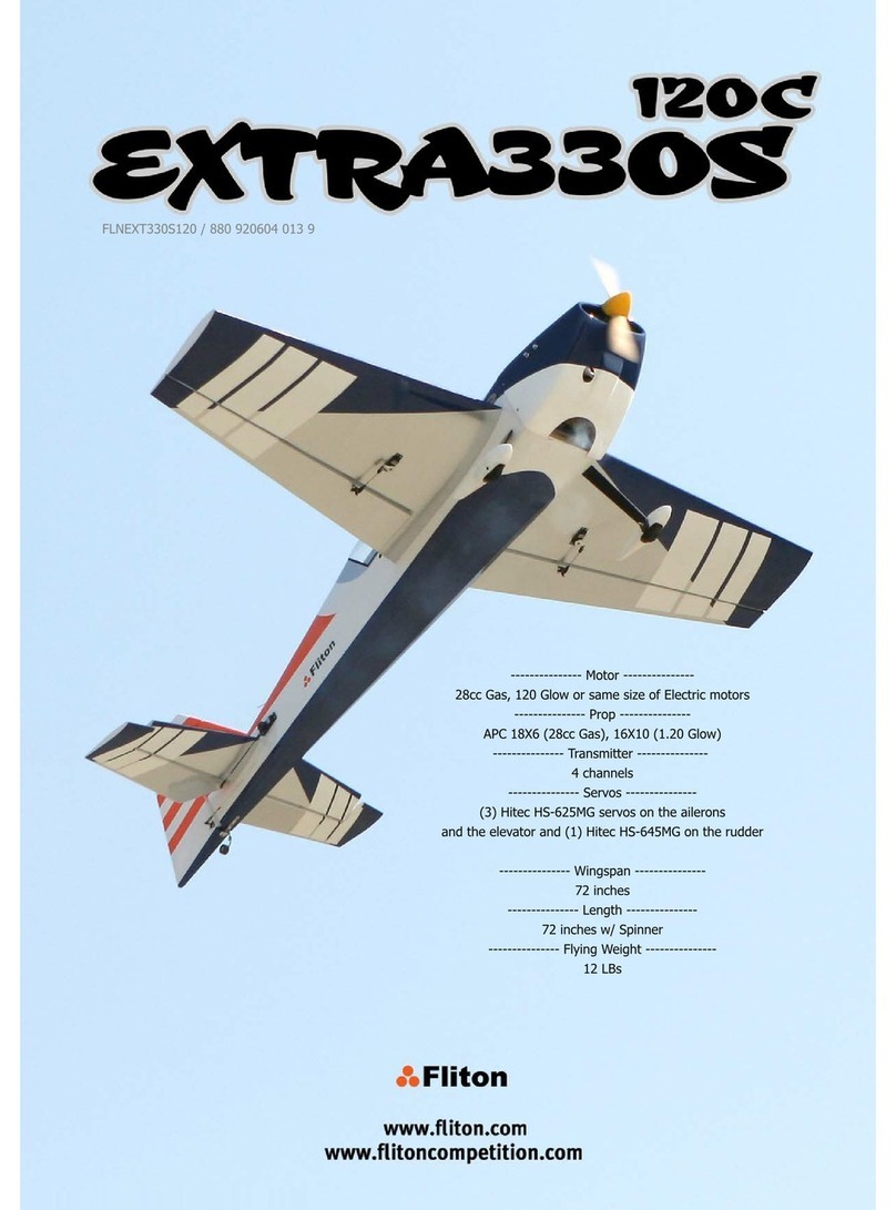
Topmodel Baia User manual

1
I
EASY
1
u
FLY
GB
-
USA
üésignaiion
~~u,~imensioipr
Vrac
noticede montage
O
1
-
iuselageavec bâti moteur mure
b&a
O1
-
-
alle avec aileron structure
balsa
02
24
cléd'aile
CIP
O1
24s
loint [onchonaile
25
mm
O1
2-2
vis
futabonaile
nylan
M6x45
mm
02
24
fixation servo ailerons
CIP+blac
balsa
Oi-i-02
2-5
-
tnngleneaileron quidc
nnk
M2
+
éirw
Ma
O2
2.
-
chape aileron chape
+
Snep
keeper
02+02
2.
-
guignol aileron qion
M3
3
-
empennage
horizontal
structure
bdsa
O1
3.5
-
tnngleneprofondeur
boa
dur
+
qui&
Ms
avec
éaw
%6
chape profondeur chape métal
+
Snap
keeper
34
guignol de profondeur nybnawc~s
4
empennage vertical structue balsa O
1
4.5
tnnglene de direction
hs
dur
+
qukk links
avec
Ccmu
44
chape direction
chape
m.l+ Snap
keeper
4.8
.
guignolde direction
don
avec
vis
84
roue
060
mm
8")
bague arrêt de roue
aœr
9.22
domino commande
gaz
mttd
98
protecicon
RIC
mousse
9SM
vis fixation moteur vis auto-taraudante
04x25
fl
98
cône d'hklice nybn
058
mn
927
reservoir hvre compkt, pr6-assmrrblk
10M
train d'atr
principal
W04m
1MI
train avant
CAP
04
mm
10s
brasde dirigibilité m/lon+a&r
tW
domino cde roue avant
rnklal
cavalierde train nylon
vis fixation train
VK
à
bon
03x6
m
24
wngloiner
Plyw60d
hl
24s
wngloint cover
25
mm
tnm adhW
tape
01
2-2
wng king
xrew
nybn
M6x45
mm
02
2-4
aileron servo mountlng
pClwood
+
balsa
Mod<
OtuoZ-
2-5
aileron pushrod
M2
m
dethreadedAre
+
nul
62
2-6
aileron clevis
mctal
devis
+
snap
keeper
02-W
2-8
aileron horn
MonM3
,
OZ
3
horizontal
stabilazer
~~asswibly
O1
3-5
elevator controllink doml+treaded rods
assemüy
Ot
3-6
elevator clevis
clew
+
snap
keeper
01+01
3-8
elevator horn donwlxrews
61.
4
verticaltail
&sa
assembk O1
-
4-5
ruddercontrolIink dwtreaded
mds
asseriMy
m
4-6
rudder clevis
dRns
+
snap keepct
01+01
4-8
rudderhorn Mnw/ screm
01
8-1
wheel
060
JWI
03
8-3
wheel collar
rtcd
06
9-22
throttle Iinkstopper
adjustabk
md
stopper
01
92F
RlC
shock protector
kun
bl
92M
engine fixing
seii
tapphg
rrew
$34~25
mm
W
925
spinner mm
M
92T
fuel tank
al
hardware, pre-assembled
P.
b*
1
OM
main undercarnage
(LG)
rusic
win
04
mm
-
k'.
nose qear mincAre
04
mm
Df
-
1
05
steenngarm
*n+*d
Op
IOST steering Iinkstopper amstable rod
stcpper
:'
81'
10-2
landingclamp
01
10-3
LG
fixing screw
seil
tappng
screw
ê3x6
mm
08
Ce modèle
à
construire n'est pas unjouet,
il
ne convient pas aux enfants de moins de
14ans.
Une mauvaise utilisation de ce matériel peut
provoquer des dommages matériels ou
corporels. Vous êtes pleinement responsable
lorsque vous utilisez votre modèle. Volez à
une distance de sécurité des zones habitées.
Soyez sûr que personne n'émet sur la même
fréquence que vous.
This model construction kit is not a toy and is
not suitable for children under the age of 14.
incorrect use of this material could cause
material damage ou personal injury. You are
fully responsable for your actions when you
use this mode!.
Fly
at a safe distance from occupied zones.
Be sure that no one else is using the same
h.equency as you.
DiesesModellflugzeug ist kein Spielzeug, es
ist fur Kinder unter 14jahren nicht geeignet.
Eine unsachgemasseverwendung dieses
Modellflugzeuges kann materielle oder
gesundheitliche Schadigungennach sich
ziehen. Bei dern gebrauch des
Modellflugzeugs tragen sie die volle
verantwortung
!
Halten sie einen
Sicherheitsabstand zu bewohntern Gebiet,
entsprechend den gesetzlichen Vorschriften,
ein. Vergewissern sie sich dass die von ihnen
benutzte Frequenz frei ist
!
Este modelo a construir no es unjuquete,
no es recomendable para ninos de edad
inferior a los 14anos.
Una mala utilization de este material puede
provocar danos materiales
O
corporales.
Vd. es el unico responsable cuando utiliza
su modelo. Vuele a una distancia prudente
de seguridad en zonas habitadas.
Asegurese que nadie emita en la misma
frecuencia que vd.
Start the work with the ~ngs
#2
Commencer par les ailes
2
Cut the coveringFilm rvherethe aileron servo
will
be Drawa center l~neon the wing loiner
#24
Dkouper l'entoilage
a
i'endroit du servo d'aileron Tracer le centre de la clk d'aile
24
iiythe fit without glue. Adjust if necessary Coat a half of the hingjoiner and wing joins pocketwith Do not forget to apply glue at the sides Coat wing joiner pocket with
30
minuteepoxy
Essayer
a
blanc I'assemblage. Ajuster si nécessaire
30
minuteepoxy Ne pas oublier d'appliquer la colle sur les côtés Enduirel'intérieur du fourreau de colle kpoxy
30
Enduirela moitié de la clé d'aile et ïintérieur du minutes
fourreau de colle 6poxy
30
minutes
lnsert wing joiner in wing half
lnskrer la cl6 d'aile dans la demi aile.
Wipe
off epoxy excess with towel and alcohol Coat the second hallof wing joiner andwingjoiner
NettoyerI'excès d'époxy avec un chiffon imbibé d'alcool pocketwith
30
minuteepoxy
Enduire
la
deuxièmemoiti6 de lacl6 d'aile et I'intérieur
dufourreau de colle époxy
30
minutes
And also, coat the wing root
Enduireégalement la face de la nervure d'emplanture
m
Wing
half-i/t
aile
H
loin upthe wing halves
Rassembler lesdemi ailes Wipe
1
;
01 epoxy
Nettoyer les bavuresde colle
j
the wing halves together with tape while epoxy
cures
Maintenirles demi ailes ensembleavec du ruban adhésif
pendantque la colle seche
The iwo wing halves roois musr nr together periectly Swilch on the radio (trim in neutral position).
..
.
..
then mounr [ne aileronservo norn in neutral position The servo horn should be perpendicularto the servo
Les demi ailes doivent avoir exactement le méme calage Allumer la radio (trim au neutre).
.. ...
puis monter le palonnierdu servo d'aileron au neutre Le palonnier doit se trouver
à
90'
de
I'axe
du servo
And
not like Ihat!
Et pas comme ceci! Mount grornmets and eyelets to the servo as shoiwn
Monter les silent blocs et les oeuilletssur le servo
comme indiqué
Cul the slot for the aileron servo cable outlet
Découperle passage du câble du servo d'ailerons
Mount the aileron servo to the tray
#2-4
hlloivthe cable to corne
up
like shown Disassemblethe aileronsservo
Monter le servo d'aiierons sur la platine
2-4
Faire sortir le câble du servo comme montré Démonter le servo d'aiierons Glue with
5
minuteepoxy balsa spacer blocks
2-4
on to
the aileron servo tray
Coller lesentretoisesbaisa
2-4
sur la platineservo
alleron
Sand the blocks
Poncer les blocs
a
laforme
Trim the spacers as needdedto fit wing dihedral ring Locale aileron servo mountingtray
angle Tracer
6
l'intrados de l'aile I'empiacement de la platine
Ajuster lesentretoisespour qu'elles s'adaptent au servo ailerons
dièdre de I'aile
Trim covenngfrom top of wing
Découperpuis enlever le film d'entoilage
à
cet endroit
5
minuteepoxy the tray in place..
.
.
.
sentered over t'
"
Coller
à
l'époxy
5
minutes la platine servo sous l'aile..
...
centréesur la réservation du serio d'ierons
Cover wing joint with self-adhesive trim strip
#24S.
Begin from that position..
.
Recouvrirlajonction des demi-ailesavec le ruban
adhesif
245.
Commencer de cette position..
.
...
IO
that one
..
.jusqu'a ici Screw up the aileronsservo
Visser le servo d'ailerons
lnstall the threadedconnectorsonto the aileron torque Screw on the alerons horns
#2-8
Use tape to maintainthe ailerons in neutral position Badl
rods
2-5
Visser les guignols
2-8
des commandes"full span" lmmobillser les ailerons au neutre
A
l'aide de ruban Mawais!
Conlectionner lescommandesd'ailerons
2-5
d'ailerons adhésif
Bend the torsion bar
1
necessary
OK!
Tordre la barre de torsion commeindiquési nécessaire. Bon!
I
Screw on metal clevis
#2-6
at least 6 mm onto #2-5
aileron pushrod
Visser (d'au moins 6 mm) les chapes 2-6 sur les
tringleries d'ailerons
2-5
Drilla
02
mm hole at the ser._
-.
..i
Percer
à
02
mm le palonnierdu servo. Cc the metalclevis #2-6
Connecter la chape métal2-6
._.
.
,,
.:e
a mark on the aileron pushrodv~hereit Then makea
90"
bend down at the mark location
crossesthe hole at the servo arm Puis. couder
à
90"
la commanded'aileron avec une
Repérer la bonnelongueurde tringlerie pour avoir pince
l'aileron au neutre
Cut the push rod
Couper la tringlerie Connedthe linkto elevator servo arm
Passer le coude dans le bras comme indique lnstall
a
snap keeper to conned pushrod and servo arm
How
to installa snap-keeper
Connecter la commandeau servo
a
I'aide du 6nau Comment installerunsnawkee~er
. .
keeperu comme montresur les photos
General view of the aileronsservo linkageinstallation Cut and remove the covering film at wing fixing screw
...
and at the bonom
of
the wing
Vue du servo d'aileron installédans l'aile Ipcations.At the top..
.
.
.
.et au-dessousde l'aile
Débouche? au cuner les trous des vis de fixation de
I'aile.Au-dessus..
.
Trim and remove the coveringfilm at horizontalstabilizer
location
"Déboucher"au cuner l'emplacementde I'empennage
horizontal(stab)
......
"..-
.emove the coveringfilm at vertical stabilizer Draw a center point on the stab
#3
Then, trace the center !ine
location Repérer le centre de l'empennage horizontal
3
Puis, tracer l'axe
"Débouche? au cutter I'emplacement de I'empennage
vertical
Center ihe stab
Centrer le stab sur le hselage
Preparea lmlong string and a modellerpin Draw a center spot on the cabin, then drive inthe pin
Préparerune cordelleted'environ 1
m
de lonq
et
une Repkrerle centre de la cabine
d
I'avant de l'aile, puis Centerthe horizontalstab with the helpof the string
PositionnerI'empennage horizontal
à
l'aide de la
cordelette
épingle de modéliste
Length of the
sirmg
must be the same both side
A=B
Don't move and draw the outlineof the fuselage to the At the top too
La
longueurde cordelette doit être la même des
2
côtés horizontalstab Au-dessus également
A=B
Sans bouger, tracer sur I'empennage la positiondu
fuselage
Trim coveringwith
a
very sharp modelingknife.
Be careful! Don't cut the balsawoodl
Découpersuivant le tracé le film d'entoilage avec un
couteautrès tranchant. Attention
à
ne oas "attaouei'
le bois
Removethe coveringboth top and bottom of the stab
Enlever lefilm
a
I'endroit ducollage. Procéderde même
pour le dessous de I'empennage
Coat the stab with
3L
m,,,,,.le epoxy (top and bittom) Put the stab inthe fuselage slot with the help of the
Enduirede colle époxy 30minutesI'empennage(dessus outline drawing.
et ~~SSOIIF) Prksenter I'empennage dans le fuselage en s'aidant du
trace pour respecter la symétrie.
Wipe off the ncess of glue. Levelthe stab to match up Put the
fin
#4
in the fuselage slot. Draw the outline of the fuselage..
with the winq. Let's dry PrésenterI'empennaqevertical
4
dans le fuselaqe Tracer le contour du fuselaqe
...
Trim coveringwithout "touching" the fixed part of the fin1
Remove the covering
Découper le film d'entoilage sans "attaquer" la partie fixe
de la dérive! Enlever le film
A
I'endroit ducollage
Essuyerlesbavuresde colle. L'empennagedoit être
horizontalau dande l'aile. Une fois aue la svmétrie est
.
,
parfaite, laisser sécher sans toucher.
Coat with 30minute epoxy Epoxy the fin into the fuselage slot Line upriththe help of a ruler and a piece of tape as Tflm
and
removethecoveringfilm at main
L.G.
location
Enduirela partie basse de l'empennagede colle époxy Coller la dérive dans la lente du fuselage shown
C=D
"Okboucher"au cutter l'emplacementdu train principalsous
30
minutes ...puistrianguler
à
l'aide d'un réglet et d'un morceau l'aile
de ruban adhésif commesur la pholo C=D
"Clean" the slot
Dégager la fente File a llat sectionwhere the retaining screw of the wheel Tighten the collars
collar applied Serrer les bagues d'arrêt
8-3
Faire des méplatssur le train principal
à
I'endroit des vis
de pressiondes bagues d'arrêt de roue.
Let a 1 mm free space between the collar
#8-3
and the
wheel
Laisser un légerjeu (Imm) pour que la roue tourne
librement
LG
#lOM
assembled
Le train principalarsemblk Put the main landing gear legs in their slot Findthe holesfor the kingxrews
Enfiler lesjambes du train ainsiassemblées dans leur Repérer les trous pour la fixationdu train
emplacement respectif
Then, screwupthe nylon straps #IO-2
Puis visser les cavaliers 10-2 comme indique
The uing rea4
L'aileterminée Fit the steenngarm #10S on to the
Z
bendsteering Slide the steering arm intothe middleof nosegear
.
.
.slide on the front leg #ION into the nylon mount,
pushrod bearing..
.
passingthrough the steeringarm
Passer la commandede train dans le trou du guignol de Présenterla commande en place au centre du palier de
...p
uis enfiler la jambe de train ION. Guignol au
dirigibilitédu train avant 10s train avant..
.
neutre, paralléle
à
l'axe de roue
Screw up
when
neutralposition is
fwnd
Serrer la vis Mount the front wheel in the same manner. Fuselage
must be parallelwith the ground
Monter de la m@mefaçon la roueavant. L'avion doit
reposer sur son train, fuselage parallèleau sol
Assemble the fuel tank
5
mm
Couper la durit de manière
à
ce que le plongeurne
touche pas la paroiarrière du réservoir
Screw up the stopper Connect thefuel lines as shown Tank locationaccording Ioengine carburator
Visser ensuite (modhrement)le bouchon Brancherla durit sur les
2
sortiesdu reservoir en lui Position du reservoirpar rapportau moteur
faisantfaire une bouclecomme sur la photo
Wdh a musicvire. make a hook
and
pullthe fuel line
Conledionner un crochet en
CAP
..
.thenroute the fuel line throughthe engine wall Put the engine on his mount. Drive washer must be few Draiv on the fuselage side the main nozzle location
...p uis passer la durit dans le trou de la cloison pare- mm fonvardfuselage sidesend Tracer sur leflanc du fuselage l'endroitde passage du
feu Présenterle moteur sur son bâti.Le moyeu porte hélice pointeaudu moteur
quelquesmm devant l'extrémité des flancs du fuselage
Remove the erqine, then miIl
Enleverle moteur puis haiser
à
I'aide d'une mini
perceuse équipée d'une meule le passage pointeau
Mark the locationof the lixingscrew on theengine Drill
4
holes03mm
mount Percer ensuite
4
trous
0
3
mm dans le bâti moteur
Pointer les trous de fixation du moteur sur le bâti
lnsertthe
Z
bendof the throttle pushrodinto the Screwin the engineon his mount with self tapping Make a needleextension with
0
1,5 mm music vire
throttlearm of the engine screws
92M
Confectionnerune rallonge pointeaudans de la CAP
Passer la CAP de commande des gaz dans le levier de Visser le moteur sur le bâti
d
l'aide des visauto- 01,5 mm
commande du boisseau du carburateur taraudantes
92M
Mount the mufner
Monterle silencieux du moteur Pull up with the hook the fuel line
Tirer avec le crochet la boucledurit Cut the fuel line
Couper la durit
Connect clunk side fuel line to the carburetior Connect the proper side to the rnuffler Prop
10x6
and spinner
92s
Connecter la durit
cdté
plongeur sur le carburateur Ajuster
sa
longueur,
pas
tropcourte pour ne pas provoquer Hélice 10x6et cône 925
de pincement.ni lrop longue pour ne
pas
gener. Connecter le
trop plein
d
la prisede pressurisation
Propellermust
be
set up as shown
L'hélice doit "attaque? la compressiondu moteur 10
A
20' aprks l'horizontale
L
al!
Tighten up the spinner
Visser l'ogive du cône Mount rudder rlevator and throttle servos to the servo Harness radioswitchmounting
tray alreatij mounted.The servos must be located as Montage de I'interrupteur réception radio
sho!vr~.Monter les servos de direction, profondeuret
gaz r4rla platine radio installie dans ie iuselage. Les
5;rvos doivent êtredans cette position
Drill servo traywith switchdrillingjig plate.Screw in the Make
a
lever to switchONlOFF the radiofrom the Follow the sequences
switch outside of the fuselage with a
01
mm music hire Suivre les étapes
Percer la platineradio
A
l'endroit de I'inter en s'aidant Confectionnerdans une îAP 01 mm, la tirette pour
de la facade de l'inter. Visser I'inter en place actionner l'inter de I'extérieur du fuselage
Measurewhere the switch lever must go out tomthe Routethe lever from Vie outsideto the insideand make Radio must
be
ON when the lever is pulled
fuselage. Reportthe distanceat the outside, then drill a
90'
bend
La
radiodoit être sur
ON
tirette tirke
Mesurer par l'intérieur du fuselagel'endroit de "sortie" Passer la tirette puis la couder
à
90'
de la tirette. Reporter cette cote
d
l'extérieur,puis
percer
RadioON, sdail the trims at neutraiposition
Radiosur
ON,
amener tous les trims au neutre
lrlm and
mm
cwMng
d
elcvator llnk exit at the rear Prep; ingle s rm for the elevator Elevalortrim at neulral position, mount the servo arm Route through the iuselage the assembly Io the elevator Iink
of the fuse Préparer un bras de servo simple pour la profondeur Trim deprofondeur au neutre. Monter le bras duservo
exl.
Découper puis enleverle film d'entoilage au niveau de la de profondeur au neutre Passer lacommande de profondeurdans leiuso et lafaire
sortie de la commandede ~rofondeur
à
I'arriere du hiso sortir
à
I'arrière
Screv: in clevis
#3-6
and his nui
Visser la chape
3-6
et son écrou Elevator horn
Montage
du
guignolde profondeur Connect the clevis to the elevator horn and then drill Mount the horn with the
2
screws.Screw in the horn
the holesfor elevator horn
#3-8.
counter- plate
Connecter la chape métalau guignolde profondeur, puis Monter le guignol de profondwr
à
I'aide des
2
vis
percer les trous pour le guignolde profondeur
3-8.
vissées dans la contre-plaque
Les trous du guignol doivent être parfaitementalignés Tape the elevator surface in neutral position lnto the fuse, markwhere the elevator linkcrosses
90
"bend carefullywhere the mark is
avec l'axed'articulation. II laut respecterle même angle Immobiliser.
h
l'aide d'un ruban adhésif, le volet de servo arm hole Plier
à
l'aide d'un étau ou d'une pince. la commande
c
entre le palonnierservo et la tringlerie et le guignolet la profondeur au neutre Dans le fuselage, repérer la longueurexacte de la profondeur
à
l'endroit repéré
tringlerie tringierie de profondeuren marquantavec un SMO
feutre l'endroit
où
vous ailez plier la
CAP
à
90"
Cut
Couper la partie en trop
Dri!:
serio
a....
.-
a2
mm. Connect the link Ioelevator Trim and removethe coveringfilm at rudder link exit Prepare a doubleservo arm for the rudder, and moun
servo arm. then, connect the snap-keeper localion adjustablesteering stopper #IOST
Percer
02
mm le bras du servo. Passer le coude dans le "Déboucher" aucuner remplacementde la sortie de la Prkparer un bras de servo double pour la direction et
bras comme indique, puis brancher le "Snap keeper"sur commandede direction monter le domino tOST pour la dirigibilité de la roue
le servo de profondeur avant
Routeîhroughthefuselage theassembly to the rudder link Connect the clevisto the horn and then drill the holes
exit. for rudder horn
#4-8.
Passer lacommandede directiondans lehiso et la faire sortir Connecter lachape métalau guignol, puis percer les
b
l'arrière trous pour le guignolde direction
4-8.
Ruddertrim still al neutral position, mount the servo Routethe rudder link aswmbly like shown
arm as shown Enfiler la tringlerie de direction dans le iuso comme
Trim de diredion toujours au neutre, monter le bras du montre sur la photo
servo de direction comme sur la photo
Eleatorand rudder links mus1
be
perfectlyin linewith
their horn as shown there.
Les commandesdoiventêtre parlaitementalignées avec
lesguignols, commesur la photo
lnto the fuse. markrvhere the rudder link crossesservo
arm hole
Dansle iuselage,repérer la longueurexacte de la
tringlerie de direction en marquantavec un stylo feutre
I'endroit où vous allez plier la CAP
à
90"
90Obend carefullywhere the mark is
Plier
d
I'aide d'une pince, la commanaeaeprofondeur
A
rendroit repéré
Cut
Couper la partieen trop
ervo arm to
02
mm. Connecî the link to rudder Then. conr
:
snap-keeper
servo arm Puis brancher le "Snap keeper"sur le servo de diredion
Percer
02
mm le bras du servo. Passer le coude dans le
Bras comme indiqué
Fit the front wheel in order the plane taxi straight ahead
Positionner la roue avant ~arfaitementdans l'axe
(l'avion doit rouler droit)
Shorten the music{vire
Couper la CAP Slip on tne nose wnee, steering link Iothe adjustablerod Prepare a singleservo arm for the throttle, and mount tully close the carburanor
stoDDer
#
10ST adiustablesto~oer
e9
2?
Fermer :crroletement le boisseaudu carburaleur
~nfilerla commandede dirigibilitéde la roue avant dans ~4~arerun
b;k
de servo simple pour les gaz et
le domino tOST monter le domino
9-22
Radio ON. selthethrottleslitk to lorv. ttim in lowest Slip on the throîile link..
.
position(erigineshut
down)
Enfiler la commandedes gaz..
Radio sur ON, gaz réduit
A
fond et trim vers le
bas
(moteuren
positionarr€l)
.
.
.then, mountthe arm to the throttle servo likeshown Screvr in throttle link stopper
...puis, monterlebras sur le servo des gaz dans la Visser le domino
position indiquée
Shortenthe musicwire
Couper l'excédent de longueurde la CAP Throttle stick to low, but trim in upper position (high
..
xarburetor must be in the show position Throitle stick at full power, trim in upper position..
.
iddle)
... ...
le
boisseaudoit occupercette position Manchepleingaz. trim toujours en haut (position ple
Manchedes gaz au ralenti maistrim en haut (ralenti gaz).
.
.
haut).
.
.
..
.carb completelyopen. Adjust throtîle link length if When thronle setting is completed, glue outer tube with Localetenter of fuse at the rear of the canopy Drilla
02
mm hole for
Rx
antennaexit
necessary
5
minuteepoxy as shown..
.
Repérer le centre du fuselage
à
I'arrière de laverrière Percer
0
2
mm le trou pour la sortie de l'antenne de
...
le boisseau
est
entièrementouvert. Ajuster la Quandle réglagede la commandedes gaz est terminé, réception
longueur de la commandedes gaz si nécesaire coller la gaine des gaz en différentsendroits
a
la
colle
époxy
5
minutescommeindiqué..
.
Bendslightlya nylonouter tube (not furnished)
Courber legèrementune gaine nylon (non fournie) Route the tube from the outside..
.
Passerla gaine souple..
.
Glue it with
CA
Coller la gaine
à
la colle cyano
...
to the radio compartment into the fuselage
.
.
.jusquSaucompartimentradio dans lefuselage
Git it
Couperla gaine au raz du fuselage Routethe
Rx
antennahom radio mmpartment to the
outside into outer tube
Enfiler I'antenne réceptiondamla gaineet lafaire
deboucher du iuselage
Dnve in a pin
al
the top ot the hn
Planter uneépingledans le sommet de la dérive Make a knot at the far end side
of
the
Rx
antenna Then anach it with a rubber band.
Faire un noeud au bout de l'antenne de rkception Puis l'accrocheraimi. Ne pas trop la tendre!
Ailerons servo extension
25
cm (not furnished)
Rallongeservo ailerons (non fournie) Connect the 25
cm
extension cord at theaileron channel Battery receiver
Brancherla rallongede 25 cm sur la voie des ailerons Accu de réception
Connect it to the
Rx
switch. Connect
Rx
switchto battery Placethe battery receiverinto the fuselage as shown Cut a piece of foam #92F Put the foam into the fuselage
channel Disposer i'accu réceptioncomme sur la photo Decouperun morceau de mousse
92F
Tapisser le fond du fuselage
Le connecter sur l'interrupteur réception. Connecter
I'inter receptionsur la voie "batterie"
Lay down the receiverand protect it with foam Cut a secondpiece of foam #92F Close with a secondlayer of foam. Let the aileron Draw at the wing top, the graviiy center position: 80
Disposer le récepteuret le proteger avec la mousse Decouper un deuxieme morceaude mouse92F extensioncord and the charqinq cord at the top mm from the leadina edae
Disposer uneautre couche
dé
housse en laissant sortir Tracer
d
I'extrados Jel'aile la ligne materialisantle
la rallongepour te branchementdes ailerons et le centre de orsvite
d
80mm du bord d'anaaue
cordon Jeiharge de I'accu
Rx
Glue
2
x
10
cm
long piensof tape overhead that line Connect the aileron servo extension Mountthe wing
Coller
2
morceaux de ruban adhésif d'environ
lOcm
de Connecter la rallongedu servo d'ailerons MonterI'aile
long
A
chevalsur cette ligne
HaH
tankfilled.
carry
the modelon your indexfingers BALANCE
locatedat tape position CENTRAGE
Rkservoirrempli moitié, porter le modélesur les index
en s'aidant du ruban adhesif commerepere
II
tailheavy.moveforwardthe banery receiver and eventualiy Balanceweight (not furnished)
the receiver too Plomb de centrage(nonfourni)
Si
lemodélepenchevers I'arriere, deplacer I'accu
Rx
et
éventuellementle récepteur vers ravant
If noseheavy. glue a pitkc balance weight at the rear Balancesidethe mode1
as
show If one wing heavy..
.
of the fuselage Equilibrerle modèlelatéralementen procédantcomme Si une aile penched'un c6té
Si le modèlepenchevers ravant, rajouter'un morceaude sur la photo
plomb sous l'étambot
...g luea balance weight underthe lighteslwing at the
wing
tip
...
coller un morceaude plombsous l'aile la plus legére
j
au saumon
Adjustconhol
sides
and control throws.
AILERONS: NEUTRAL WSlTlON
Réglerle sens et ledbbattementdes gouvernes.
AILERONS AU NEUTRE
UP:
15mm-DOW: 15mm
VERS LE
HAUT:
15 mm
-
VERS LE
BAS:
15 mm ELEVATOR:NEUTRAL POSITION
PROFONDEUR
AU
NEiJTRE
UP:
15mm-DOWN: 15mm RUDDER: NEUTMLPOSITION
VERS
LE
HAUT:
15 mm -VERS
LE
BAS: 15 mm DERIVE
AU
NEUTRE

This manual suits for next models

1

Other Topmodel Toy manuals

Topmodel Joy2Fly User manual

Topmodel

Topmodel Joy2Fly User manual

Topmodel ECOTOP CHARLIE WHISKY User manual

Topmodel

Topmodel ECOTOP CHARLIE WHISKY User manual

Topmodel 0666G003-TR User manual

Topmodel

Topmodel 0666G003-TR User manual

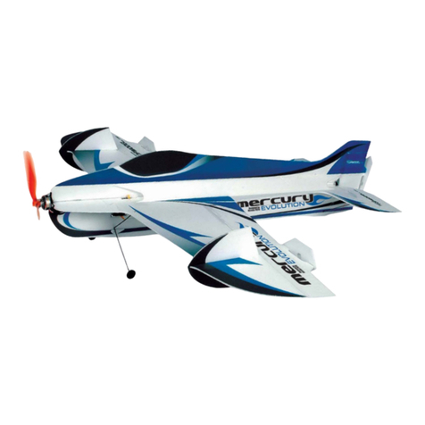
Topmodel XPower mercury EVOLUTION User manual

Topmodel

Topmodel XPower mercury EVOLUTION User manual

Topmodel Condor User manual

Topmodel

Topmodel Condor User manual

Topmodel BIDULE 55 ECOTOP User manual

Topmodel

Topmodel BIDULE 55 ECOTOP User manual

Topmodel ECOTOP BIKINI User manual

Topmodel

Topmodel ECOTOP BIKINI User manual

Topmodel Pegasus 2E F5J/ALES User manual

Topmodel

Topmodel Pegasus 2E F5J/ALES User manual

Topmodel Baron User manual

Topmodel

Topmodel Baron User manual

Topmodel MALADIETS User manual

Topmodel

Topmodel MALADIETS User manual

Topmodel Maracana User manual

Topmodel

Topmodel Maracana User manual

Topmodel IPANEMA II XPower User manual

Topmodel

Topmodel IPANEMA II XPower User manual

Topmodel Discus 2c User manual

Topmodel

Topmodel Discus 2c User manual

Topmodel ExtraCT ECOTOP User manual

Topmodel

Topmodel ExtraCT ECOTOP User manual

Topmodel Grafas User manual

Topmodel

Topmodel Grafas User manual

Topmodel 066111 User manual

Topmodel

Topmodel 066111 User manual

Topmodel Ecotop Scale Series User manual

Topmodel

Topmodel Ecotop Scale Series User manual

Topmodel Ecotop Waka User manual

Topmodel

Topmodel Ecotop Waka User manual

Topmodel KOSMOS 09919 User manual

Topmodel

Topmodel KOSMOS 09919 User manual

Topmodel PILATUS B4 User manual

Topmodel

Topmodel PILATUS B4 User manual

Topmodel Saturn Evolution Biplan de competition... Operation and maintenance manual

Topmodel

Topmodel Saturn Evolution Biplan de competition... Operation and maintenance manual

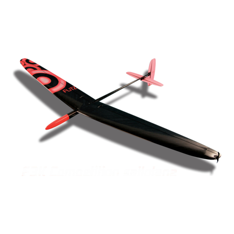
Topmodel F3K FLITZ 2 User manual

Topmodel

Topmodel F3K FLITZ 2 User manual

Topmodel XPower Krasivo 2 User manual

Topmodel

Topmodel XPower Krasivo 2 User manual

Topmodel ECOTOP JOYSTICK User manual

Topmodel

Topmodel ECOTOP JOYSTICK User manual

Popular Toy manuals by other brands

Helios Rivos operating instructions

Helios

Helios Rivos operating instructions

CREATIVE CONCEPTS Pucker Powder Assembly and mounting instructions

CREATIVE CONCEPTS

CREATIVE CONCEPTS Pucker Powder Assembly and mounting instructions

Clancy Aviation Big Bee Instructions for assembly

Clancy Aviation

Clancy Aviation Big Bee Instructions for assembly

Hangar 9 Alpha 40 ARF Assembly manual

Hangar 9

Hangar 9 Alpha 40 ARF Assembly manual

THUNDER TIGER Vocans instruction manual

THUNDER TIGER

THUNDER TIGER Vocans instruction manual

PARKZONE Stinson Reliant SR-10 instruction manual

PARKZONE

PARKZONE Stinson Reliant SR-10 instruction manual

Faller 2280 quick start guide

Faller

Faller 2280 quick start guide

4M Tyrannosaurus Rex Robot instructions

4M

4M Tyrannosaurus Rex Robot instructions

Fisher-Price P3329 manual

Fisher-Price

Fisher-Price P3329 manual

Faller ARCHED BRIDGE quick start guide

Faller

Faller ARCHED BRIDGE quick start guide

Zapf Creation CHOU CHOU Magic Pacifier quick start guide

Zapf Creation

Zapf Creation CHOU CHOU Magic Pacifier quick start guide

Carrera 30357 Assembly and instruction manual

Carrera

Carrera 30357 Assembly and instruction manual

Showcase 5008 Assembly manual

Showcase

Showcase 5008 Assembly manual

Mattel Barbie instructions

Mattel

Mattel Barbie instructions

Lionel 726 Berkshire 2-8-4 steam locomotive operating instructions

Lionel

Lionel 726 Berkshire 2-8-4 steam locomotive operating instructions

MD Helicopters 500 manual

MD Helicopters

MD Helicopters 500 manual

Dynam SkyTrainer instruction manual

Dynam

Dynam SkyTrainer instruction manual

Jamara Fendt Tank Wagon instructions

Jamara

Jamara Fendt Tank Wagon instructions

manuals.online logo
manuals.online logoBrands
  • About & Mission
  • Contact us
  • Privacy Policy
  • Terms and Conditions

Copyright 2025 Manuals.Online. All Rights Reserved.