manuals.online logo
Brands
  1. Home
  2. •
  3. Brands
  4. •
  5. Giant
  6. •
  7. Water Pump
  8. •
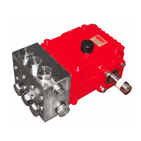
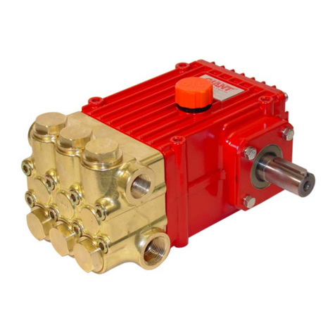
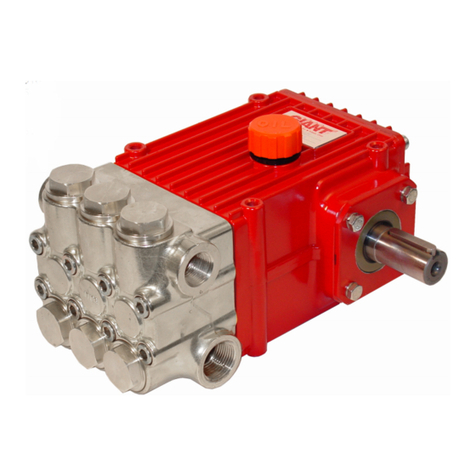
  9. Giant GEARBOX Series User manual

Giant GEARBOX Series User manual

Contents:
Installation Instructions: page 2
Operating Instructions: page 3
Pump Specications: page 4
Repair Kits: page 5
Tool List: page 5
Exploded View: page 6
Parts List: page 7
Repair Instructions: pages 8-10
Troubleshooting Chart: page 11
Torque Specications: page 11
Dimensions: back page
Warranty Information: back page
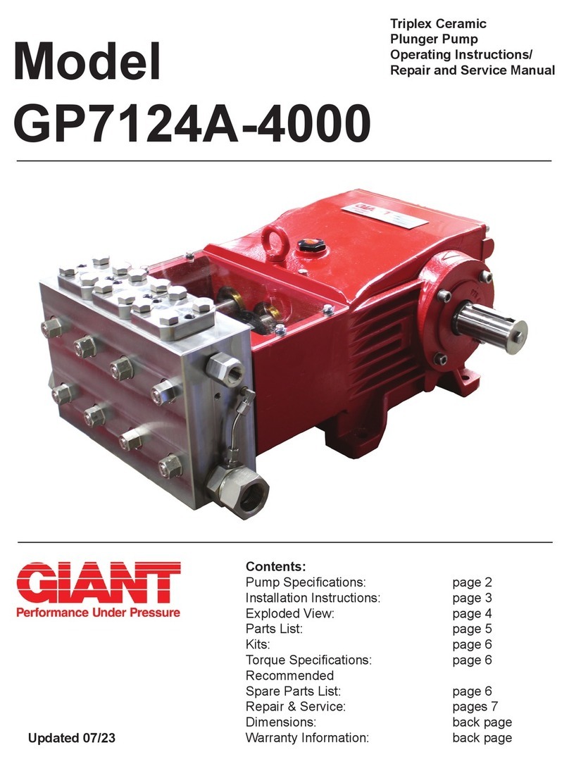
Triplex Ceramic
Plunger Pump
Operating Instructions
Repair and Service Manual
Series
GP8155(-1000)
GP8160(-1000)
GP8165(-1000)
GEARBOX SERIES
GP8100 - Spheroidal Nickel-Plated Cast Iron Manifold
GP8100-1000 - Bronze Manifold
Updated 03/22
2
20 minutes an hour, with the pump running with-out
pressure or turned o󰀨 in between. For example, this
can be full load operation for 5 minutes four times an
hour with 10 minute breaks in between or continuous
full load operation for 20 minutes followed by a 40
minute break.
IMPORTANT! If higher medium temperatures or
liquids other than water are involved or aggressive
media such as seawater, demineralised water etc., the
pump must be tted with a separate cooling circuit.
The separate cooler must have a cooling e󰀩ciency of
1700 watt. If there is a danger of frost, an appropriate
amount of antifreeze must be mixed into the cooling
circuit.
When starting up for work, the pump must run rst at
zero pressure for approximately 1 minute.
IMPORTANT! The GP8100 series has a black arrow
on the reduction gear which shows the preferred
direction of rotation. The pumps can be de-livered
either with the gear on the left side or right side which
eases the planning of assembling units with regard to
rotational direction.
Gear on right side from behind pump = optimal
rotation: to the left
Gear on left side from behind pump = optimal rotation:
to the right
The preferred/optimal direction of rotation ensures the
motion of the connecting rods correctly shovels the
oil on to the crosshead guides – which is a particular
advantage where continuous operation is involved.
The pump can also be run against the recommended
direction of rotation if operated periodically or at
reduced pressure. If so, the pump has to be run in
in this direction to smoothen the bearing areas. This
is done by a one-time operation at zero pressure for
at least 30 minutes; thereafter the pressure must be
slowly increased over the next hour to the desired
maximum operating pressure; the pump is then run in.
Check the oil temperature during this process.
IMPORTANT! The pump and cooling system must be
emptied if there is a danger of frost. Travel wind can
cause water in pumps tted on open vehicles to freeze
even if the outside temperature is above freezing
point.
To empty the cooling circuit, remove the L-joints (K11)
on the pump head (50). Blow out the circuit liquid at
the joint connection (K11/K7) using compressed air.
The torque tenson on the valve casing nuts (49A) is to
be checked after approximately 200 operating hours.
Please see the section ‘Maintenance’ concerning the
torque values.
The pump must be at zero pressure when checking
the torque tension.
IMPORTANT! The service life of the seals is
maximized if a minimal amount of leckage is present.
A few drops of water can drip from each plunger every
minute. Leakage has to be examined every day;
the plunger seals must be changed should leckage
become excessive (=constant dripping).
INSTALLATION INSTRUCTIONS
The stated gures are for maximum pressure
and maximum speed (rpm) and apply for interval
operation with cold water.
Required NPSH refers to water (specic weight 1kg/
dm3, viscosity 1°E) at maximum permissible pump
revolutions.
Fluid medium: Clean water ltered with 200μm.
*higher temperatures possible with separate
crankcase cooling system; the manufacturer is to be
contacted in this case.
Operation and Maintenance
Check oil level prior to starting and ensure trouble-
free water supply.
IMPORTANT! If there is a danger of frost,
the water in the pump and in the pump ttings
(particularly the unloader valve) must be emptied.
The second discharge port can also be used and the
pump run “dry” for 1-2 minutes for this purpose.
Oil amount: 4.2 gallons (16.0 litres). Only use ISO
VG 220 industrial gear oil (e.g. Aral Degol BG220)
or automobile gear oil SAE 90 GL4. Initial change
after 50 operating hours and then every 1000
operating hours after one year latest.
IMPORTANT! When operating in damp places
or with high temperature uctuations. Oil must be
changed immediately should condensate (frothy oil)
occur in the gear box.
NPSH values must be observed.
Cooling the Gear Oil
IMPORTANT! The water input pressure must not
exceed 29 PSI (2 bar) when using the integrated
system for cooling the gear oil (standard version).
If a separate cooling circuit (maximum 29 PSI [2
bar]) is installed, it is then possible to have an input
pressure of up to maximum 145 PSI (10 bar) on the
suction side of the pump.
Make sure that suction pulsation is su󰀩ciently
dampened – water column resonance must be
avoided.
IMPORTANT! The pumps can be run without gear
oil cooling in continuous operation up to a power
rating of 93.9 HP (70 kW) or with major intermit-tent
operation at full performance.
If operational power exceeds 93.9 HP (70 kW) or if
continuous operation is the case, the pump must be
run with the integrated oil cooling system. The max.
temperature of the water being pumped and which is
also fed through the cooling system must not exceed
86 °F (30 °C). The water amount which is fed into
the cooling system depends on the pump speed and
is approximately 1.9 GPM (7.0 L/min) at 580 pump
rpm. The cooling water is sucked in by one of the
pumping chambers and pumped away.
Denition of intermittent operation: operation
at full performance for not more than altogether
3
Safety Rules
The operating instructions must be read and
adhered to before performing any work on
the pump or complete assembled unit. No
responsibility will be carried by us for damage
to materials or per-sons caused by improper
handling of our pumps.
Access to the pump is not allowed for unauthorized
personnel. A safety valve is to be installed in
accordance with the guidelines for liquid spraying units
so that the admissible operating pressure cannot be
ex-ceeded by more than 10%. Pump operation without
a safety valve as well as any excess in temperature or
speed limits automatically voids the warranty.
When the pump is in operation, the driven shaft side
and its coupling must be covered by a protective
guard. The plunger area must also be covered by the
protective plate (30).
Do not step onto the protective plate (30) nor put
weight on it.
Pressure in the discharge line and pump must be at
zero before carry-ing out any maintenance work to the
pump or unit. Close o󰀨 suction line. Disconnect fuses
to ensure that the driving motor cannot get switched
on accidently. Make sure that the pump, the cooling
system and all parts on the pressure side of the unit
are vented and relled, with pressure at zero, before
starting the pump.
In order to prevent air or an air/water-mixture
being absorbed and cavi-tation occurring, the
pump-npshr, positive suction head and water
tem-perature must be respected.
Cavitation and/or compression of gases
lead to uncontrollable pressure-kicks which
can ruin the pump and unit parts and also
be dangerous to the operator or anyone
standing nearby.
Giant plunger pumps are suitable for pumping
clean water and other non-aggressive or non-
abrasive media with a specic weight similar to
water.
Before pumping other liquids - especially
inammable, explosive and toxic media -
the pump manufacturer must be consulted
with regard to the resistance of the pump
material. It is the responsibil-ity of the
equipment manufacturer and/or operator to
ensure that all pertinent safety regulations
are adhered to.
OPERATING INSTRUCTIONS
4
Model ....................................................... Gear Ratio..................................Input Speed
GP8100-2.6 ................................................... 2.6:1 .........................................1500 RPM
GP8100-3.1 ................................................... 3.1:1 .........................................1800 RPM
GP8100-3.8 ................................................... 3.8:1 .........................................2200 RPM
GP8100-4.5 ................................................... 4.5:1 .........................................2600 RPM
HORSEPOWER RATINGS: The rating shown are the power requirements for the pump. Gas engine
power outputs must be approximately twice the pump power requirements shown above.
We recommend a 1.15 service factor be specied when selecting an electric motor as the power source.
To compute specic pump horsepower requirements, use the following formula:
GPM X PSI
1450
Specications
Consult the factory for special requirements that must be met if the pump is to
operate beyond one or more of the limits specied above.
= HP
Maximum
Flow
Maximum
Pressure
Maximum
Speed
Power
Required
Plunger
Diameter
NPSHR
Model GPM PSI RPM HP in foot of head
GP8155 75.5 3000 580 145 2.17 23
GP8160 90 2500 580 147 2.36 23.6
GP8165 105.6/120* 2000 580/658 142/166 2.55 26.2
Max. Flow Maximum
Pressure
Maximum
Speed
Power
Required
Plunger
Diameter
NPSHR
Model L/min Bar RPM kW mm mWs
GP8155 285 200 580 108 55 7.0
GP8160 337 170 580 110 60 7.2
GP8165 400/455* 140 580/658 106/123 65 8.0
U.S. Measurements
Metric Measurements
U.S. (Metric)
Maxiumum Inlet Pressure ................................ Up to 29 PSI* .......................(2.0 bar)*
Plunger Stroke ................................................. 2.83” .....................................72mm
Maximum Temperature of Pumped Fluids ....... Up to 86 oF*.......................... (30 oC)*
Pinion Shaft Diameter ...................................... 1.77” ..................................... 45 mm
Key Width ...................................................................................................... 14 mm x 9 mm x 70 mm
Crankshaft Mounting .....................................................................................Either side
Shaft Rotation ................................................................................................ See Page 2
Inlet Ports ......................................................................................................(2) 3” BSP
Discharge Ports .............................................................................................(2) 1-1/4” BSP
Crankcase Oil Capacity ................................... 4.2 Gal. ............................... (16.0 liters)
Weight ............................................................. 794 lbs. ................................(360 kg)
Fluid End Material (GP8155/GP8160/GP8165) ............................................. Nickle plated Spheroidal Cast Iron
Fluid End Material (-1000 versions) ...............................................................Bronze
*The specications above are based on maximum pressure and RPM for intermittent duty using cold water.
5
Pump Repair Kits - GP8155/GP8160/GP8165
Plunger Packing Kit - GP8155
# 09616
Item Part # Description Qty.
38A 13286 O-Ring 6
38B 05281 Support Ring 6
39A 05066 O-Ring 3
40 07723 Seal Ring 3
42 05277 Sleeve 9
Plunger Packing Kit - GP8160
# 09617
Item Part # Description Qty.
38A 06667 O-Ring 6
39A 05066 O-Ring 3
40 05067 Seal Ring 3
42 05069 Sleeve 9
Plunger Packing Kit - GP8165
# 09586
Item Part # Description Qty.
38A 06667 O-Ring 6
39A 05066 O-Ring 3
40 06996 Seal Ring 3
42 06997 V-Sleeve 9
Inlet Valve Kit
#09587
Item Part # Description Qty.
51B 05078 Inlet Valve Seat 1
51C 05079 Valve Plate 1
51D 07658 O-Ring 1
51E 05080 Valve Spring 1
56A 06258 O-Ring 1
Discharge Valve Kit
#09588
Item Part # Description Qty.
52B 05084 Discharge Valve Seat 1
52C 05079 Valve Plate 1
52D 06258 O-Ring 2
52E 05080 Valve Spring 1
56A 06258 O-Ring 1
Oil Seal Kit
#09584A
Item Part # Description Qty.
32 05058 Radial Shaft Seal 3
32A 03118 Scraper 3
33A 05056 O-Ring 3
6
Exploded View - GP8155/GP8160/GP8165
7
Parts List - GP8155/GP8160/GP8165
Item Part Description Qty
1 05651 Crankcase 1
2 06893 Oil Filler Plug Assy. with Vent 1
3 05652 Rear Foot for Crankcase 2
4 05653 Front Foot for Crankcase 2
5 05654 Hexagon Socket Screw 4
6 05655 Hexagon Socket Screw 4
7 05656 Plug, 3/8” for Oil Dipstick 1
8 04185 Oil Dipstick Assembly 1
9 01009 O-Ring 1
10 05657 Plug M33 X 1.5 1
11 07102 O-Ring 1
12 12256 Plug 3/8” BSP 3
13 22929 Copper Washer 4
14 05036 Bearing Cover Closed 1
16 05037 O-Ring 1
17 05038 Hexagon Socket Screw M12 8
18 05039 Spring Ring 8
19 05765 Flange 1
19A 05766 Hexagon Socket Screw 6
20 05658 Tapered Roller Bearing 1
21 05659 Tapered Roller Bearing 1
21A 05042 Fitting Disc 3
21B 05043 Fitting Disc 3
21C 05113 Fitting Disc 3
22 05741 Crankshaft For Gear 1
23 05661 Fitting Key 1
24 05047 Conn-rod Assembly 3
25 05048 Crosshead c/w Plunger 3
28 05049 Crosshead Pin 3
29 05051 Hexagon Screw 6
29A 07408 Hexagon Nut 2
29B 05383 Bracket 2 for Cooling Hose 2
29C 05662 Support Clamp 2
29D 05381 Bracket 1 for Cooling Hose 1
30 05052 Cover Plate 1
30A 07225-0100 Hexagon Screw 5
30B 13136 Grommet 5
30C 08280 Washer 9
30D 05050 Splash Cover 1
31 07623 Eye Bolt 4
32 05058 Radial Shaft Seal 3
32A 03118 Scraper 3
33 03119 Seal Retainer 3
33A 05056 O-Ring 3
33B 05054 Clip Ring 3
33C 05059 Fitting Disc 3
34 05060 Oil Shield 3
36A 05063 Plunger Pipe Cover,
GP8160/GP8165 3
36B 05280 Plunger, GP8155 3
36B 05061 Plunger, GP8160 3
36B 05115 Plunger, GP8165 3
36C 05062 Tension Screw 3
36D 07665 Copper Washer 3
36E 06900 Centering Sleeve 3
38 05283 Seal Case, GP8155 3
38 05064 Seal Case, GP8160/GP8165 3
38A 13286 O-Ring, GP8155 6
38A 06667 O-Ring, GP8160/GP8165 6
38B 05281 Support Ring, GP8155 Only 6
39 05275 Seal Sleeve, GP8155 3
39 05065 Seal Sleeve, GP8160 3
39 05116 Seal Sleeve, GP8165 3
39A 05066 O-Ring 3
40 07723 Seal Ring, GP8155 3
40 05067 Seal Ring, GP8160 3
40 06996 Seal Ring, GP8165 3
41 05276 Pressure Ring, GP8155 3
41 05068 Pressure Ring, GP8160 3
41 05117 Pressure Ring, GP8165 3
42 05277 Sleeve, GP8155 9
42 05069 Sleeve, GP8160 9
42 06997 Sleeve, GP8165 9
43 05278 Sleeve Support Ring, GP8155 3
43 05070 Sleeve Support Ring, GP8160 3
43 05118 Sleeve Support Ring, GP8165 3
Item Part Description Qty
45 05279 Seal Tension Spring, GP8155 3
45 05071 Seal Tension Spring, GP8160 3
45 05119 Seal Tension Spring, GP8165 3
49 05072 Stud Bolt 8
49A 05073 Hexagon Nut 8
50 05074 Valve Casing,
GP8155/GP8160/GP8165 1
50 05074-3000 Valve Casing, -1000 Versions 1
50A 13162 Centering Stud 2
50B 05075 Discharge Casing,
GP8155/GP8160/GP8165 1
50B 05075-3000 Discharge Valve Casing,
-1000 Versions 1
51 04186 Suction Valve Assembly 3
51A 04166 Spring Tension Cap 3
51B 05078 Suction Valve Seat 3
51C 05079 Valve Plate 3
51D 07658 O-Ring 3
51E 05080 Valve Spring 3
52 04188 Discharge Valve Assembly 3
52A 04166 Spring Tension Cap 3
52B 05084 Discharge Valve Seat 3
52C 05079 Valve Plate 3
52D 06258 O-Ring 6
52E 05080 Valve Spring 3
56 05085 Discharge Valve Adaptor 3
56A 06258 O-Ring 3
57 05086 Pressure Spring 3
57A 07210-0100 Pressure Spring 3
58 05087 Hexagon Socket Screw 12
59 07109 Plug, 1/2” BSP 2 (3*)
59A 06272 Copper Seal 2 (3*)
60 06909 Plug, 1-1/4” BSP,
GP8155/GP8160/GP8165 1
60 13151 Plug, 1-1/4” BSP, -1000 Versions 1
61 05088 Plug, 3” BSP 1
62 05302 Plug, 1/4” BSP 6
62A 06934 Copper Gasket 6
66 03193 Gear Cover 1
67 08484 Hexagon Screw 11
67A 08041 Washer 11
68 04445 Cylinder Pin 2
69 04171 Gear Wheel Set (1500 RPM=2.6) 1
69 04170 Gear Wheel Set (1800 RPM=3.1) 1
69 05767 Gear Wheel Set (2200 RPM=3.8) 1
69 05666 Gear Wheel Set (2600 RPM=4.5) 1
70 07614 Fitting Key 1
71 04571 Spacer Ring 1
72 05667 Hexagon Screw 1
73 05608 Shaft Seal Ring for Gear 1
74 05668 Self-Aligning Roller Bearing 1
75 05669 Roller Bearing 1
75A 05670 Fitting Disc 1
76 03309 Gear Seal 1
78 05025 Oil Cooler (Items K1 - K19) 1
79 07662 Valve Puller (Not Shown) 1
K1 05026 Cooling Vane Plate 1
K2 05027 Seal for Gear Cover 2
K3 05028 Gear Cover 1
K4 05029 Hexagon Hd Cntrsnk Screw 4
K5 07381 Hexagon Socket Screw 8
K6 08041 Washer 8
K7 05030 Connection for Oil Cooler 1
K8 06272 Copper Seal 6
K9 07109 Plug, 1/2” BSP 2
K10 05031 Connecting Branch 3
K11 05032 U-Joint Connector c/w Nut 3
K12 05033 Tube for Cooler 2
K13 05402 Hose Clamp 4
K14 05403 Hose Guard 2
K15 05404 Hose Coupling Nut 1
K16 05405 Flat Gasket 4
K18 04158 Hexagon Socket Screw 4
K19 05053 Washer 4
*3 pieces for GP8155/GP8160/GP8165
8
Pump Repair Instructions - GP8155/GP8160/GP8165
6) Remove tension screw (36C) and take
seal sleeve (39) together with all mounted
parts out of the drive. Pull plunger pipe (36B)
out of the seal assembly and check for any
damage. Carefully, remove seal rings (40) and
sleeves (42) with a screwdriver.
4) Remove valve assembly (52) from discharge valve adapter (56) by gently twisting apart. The spring
tension cap (51A, 52A) is screwed together with the valve seat (51B or 52B). Remove spring tension cap.
Takeout springs (51E, 52E) and valve plate (51C, 52C). Check sealing surfaces of valve plates (51C &
52C) and valve seats (51B & 52B) and O-rings (51D, 52D). Replace worn parts. Coat threads of valve seat
with silicon grease or molycote anti-seize Cu-7439 when reassembling. Before retting the valves, clean
the sealing surfaces in the casing and check for any damage. Coat o-rings (51D, 52D & 56A) with silicone
grease to help with re-assembly. Replace valve assembly (51) and pressure spring (57). Assemble valve
assembly (52) to discharge valve adapter (56) by tapping together lightly with rubber mallet. While replacing
the valve assemblies use a rubber mallet to tap the top of the valve puller lightly. This insures proper seat-
ing. Replace pressure spring (57A) and the discharge casing (50B). Tighten caps (58) at 132 Ft-lbs. (180
Nm); check torque tension after 8-10 operating hours.
5) Remove hexagon nuts (49A) and valve
casing together with seal case (38) from
crankcase (1). If necessary, carefully tap the
valve casing (50) past the centering stud
(50A) using a rubber hammer.
IMPORTANT! If necessary, support the valve
casing by resting it on wooden blocks or by
using a pulley.
Valve Inspection and Repair
1) Remove socket head cap
screws (58)
2) Lift discharge casing
(50B) up and away.
3) Take out pressure springs
(57A). Pull out assembled
valves (51 & 52) with valve puller.
To Check Seals and Plunger Pipe
9
7) Be careful not to damage the seal
sleeve (39) and pressure ring (41). Check the inner
diameter of the pressure ring for wear and if neces-
sary replace together with seals (40) and (42). Clean
all parts. New parts should be lightly coated with
silicon grease before installation. Insert the seal unit
(40, 41, 42 43) into the sleeve. Push the ceramic
plunger carefully through the seals from the crank-
case side. If necessary, the seals can be held tightly
using a suitable pipe support held on the other side
of the seal sleeve.
8) Take out the seal case (38) from the valve
casing (50) and check o-rings (38A) (if necessary
secure two screwdrivers in the front o-ring groove
to extract seal casing from valve casing). Coat
seals with silicon grease before installing.
Mounting surfaces of the crankcase
and the valve casing must be clean and free of
damage. The components must lie exactly and
evenly on one another. The same exactness ap-
plies for all centering positions in the crankcase,
pressure and valve casing.
9) Coat the seal sleeve(39) lightly with anti-corrosive
grease (e.g. molycote no.Cu-7439) in its tted area
towards the crankcase. Insert the seal sleeves in to
their crankcase ttings. Coat the threads of the ten-
sion screw (36C) lightly with thread glue and insert
it together with a new copper ring (36D) through
the ceramic pipe. Turn the pump by hand until the
plunger (25) rests against the plunger pipe. Tighten
the tension screw at 30 Ft-lbs. (40 NM)
Thread glue must never come between
the plunger pipe (36B) and centering sleeve (36E).
Overtensioning of the plunger pipe by excessive
tightening of the tension screw and/or dirt or damage
on the mounting surfaces can lead to plunger pipe
breakage. Insert the seal tension spring (45) and o-
ring (39A) in to the seal sleeve (39).
Replacing Valve Casing:
10) Put seal cases (38) in the centering holes of the
valve casing, then push valve casing carefully on to
centering studs (50A). Tighten hexagon screws (49A)
evenly and crosswise at 265 Ft.-lbs. (360 NM). Follow
pattern below.
The torque tension on the screws (49A)
must be checked after 8-10 operating hours; the pump
must be at zero pressure. Thereafter, the tension is to
be checked every 200 operating hours.
Pump Repair Instructions - GP8155/GP8160/GP8165
10
Pump Repair Instructions - GP8155/GP8160/GP8165
To Dismantle Gear
Take out plungers and seal sleeves as described above.
Drain oil by taking o󰀨 plug (12).
After removing the clip ring (33B), remove the seal retainer (33) with a screwdriver. Open hose adaptor (K11).
Remove gear cover (K3) and remove the cooling vane plate (K1) by unscrewing the screws (K4). Remove
connecting rod screws (24).
IMPORTANT! Connecting rods are marked for identication. Do not twist connecting rod halves or
interchange them. When reassembling, the connecting rods must be tted in their exact original position on
the crankshaft journals.
Push connecting rod halves together with the crosshead as far as possible into the crosshead guide.
Remove bearing cover (14), remove shims (21A/B).
To Dismantle Gearbox
Remove screws (67). Press o󰀨 gear cover (66) by screwing two screws into both thread bores. Remove
screw (72) and take o󰀨 plate (71). Remove the gearwheel (69) from the shaft with a bearing removal tool.
Using a rubber hammer, tap out the crankshaft towards bearing cover (14).
Check surfaces on the connecting rods (24), crankshaft (22) and crossheads (25). Check the surfaces of the
crosshead guides in the crankcase (1) for any unevenness.
Reassemble in reverse order. Thread the crankshaft in from the bearing cover side until the bearing rests
cleanly in the outer ring on ange (19).
Press in the outer ring from bearing (20) and using shims (21A/B/C), adjust the bearing to be free of play. To
achieve this, add shims, screw on cover (14) and turn the crankshaft until it can no longer be turned by hand.
Then remove a shim and establish whether the crankshaft can now be turned. A crankshaft that can be
too easily turned may cause damage to the bearings (20/21) and connecting rods (24) due to the wobble
movements in the conical bearing shells.
If bearings (20 & 21) have been replaced, the ange (19) must be taken o󰀨 and a new bearing outer ring
pressed in until the surfaces are even. Then mount the holding ange to push the bearing outer ring in
deeper.
Mount connecting rod halves in their exact original position and tighten at 37 ft.-lbs. (50 Nm).
IMPORTANT! A little clearance must exist to enable slight sideward movement of the connecting rod on its
journal.
Mount cooler plate (K1) and gear cover (K3) with their respective seals (K2). When assembling the cooling
circuit line, make sure that the oil cooler connection (K7) is always joined to the upper connection (K3) of the
gear cover.
To Reassemble Gearbox
Heat ball bearings (74 & 75) rst before pressing them onto the pinion. Press the cogwheel slightly onto the
crankshaft (22) so that the pinion shaft (69) together with the bearing (74) can still be inserted.
Move the pinion shaft against the cogwheel and make them mate perfectly when mounting. Carefully tap the
cogwheel and the pinion shaft simultaneously onto the crankshaft and into the bearing seat.
Fit tting disc (69), and secure screw (72) with Loctite.
Fit the seal (76) onto the cylindrical pins (68).
Push the gear cover (66) carefully onto the bearing (75). Make sure that no damage to the radial shaft seal
(73) occurs during the tting onto the pinion shaft.
IMPORTANT! Before putting into operation again, turn the reduction gear shaft by hand at least four full turns
to make sure the gear is correctly aligned.
11
TROUBLESHOOTING
Problem Cause Solution
Pressure Drops, water leaks V-sleeves leak Replace V-sleeves, check surface of
plunger
Pressure drops, pump gets loud Discharge or suction valve leaks Replace valve(s)
Steam formation (Cavitation) Reduce suction height, reduce ow
resistance in inlet line, clean inlet
lter, lower water temperature.
Irregular pressure Worn Valves Examine valves
O-ring on valves or inlet valve
adapter leaks Examine O-rings, check valve
casing for unevenness on the
sealing surfaces
Oil leaks at visible part of plunger Gear sealing is leaking Examine seals and running surface
of plunger
Dirty, milk-colored or frothy oil Water has mixed with oil Replace oil immediately, nd & x
the cause
Oil leakage on the crankshaft Shaft seal ring leaks Check seal and shaft
Noise increases without the loss Worn bearing Dismantle gear, examine all parts,
replace worn parts, check oil level. If
service life was too short, check for
excess strain or whether lubrication
intervals were too long. Only
specied lubricants are to be used.
Troubleshooting
GP8155/GP8355/GP8160/GP8360/GP8165/GP8365
TOOL LIST AND TORQUE SPECIFICATIONS
Item Part # Description Torque Ft-Lbs (NM) Tool Needed
17 05038 Hexagon Socket Screw 64 (87) 10mm Allen Wrench
24 05047 Connecting Rod Hex. Hd. Socket Screw 37 (50) 8mm Allen Wrench
33B 05054 Clip Ring N/A Industrial Snap Ring Pliers
36C 05062 Tension Screw 30 (40) 16mm Socket
49A 05073 Hexagon Nut (Manifold) 265 (360) 30mm Socket
51 & 04188 & Valve Assemblies N/A Valve Puller (p/n 07662)
52 04186 included w/pump
58 05087 Hexagon Socket Screw 132 (180) 12mm Allen Wrench
K5 07381 Hexagon Socket Screw N/A 8mm Allen Wrench
Torque Specications - GP8155/GP8160/GP8165
GIANT INDUSTRIES, INC., 900 N. Westwood Ave., Toledo, Ohio 43607
PHONE (419) 531-4600, FAX (419) 531-6836, www.giantpumps.com
 Copyright 2022 Giant Industries, Inc. 03/22 GP8155_GP8160_GP8165.indd
GIANT INDUSTRIES LIMITED WARRANTY
Giant Industries, Inc. pumps and accessories are warranted by the manufacturer to be free from
defects in workmanship and material as follows:
1. Five (5) years from the date of shipment for all pumps used in portable pressure
washers with NON-SALINE, clean water applications.
2. Two (2) years from the date of shipment for Giant pumps used in car wash
applications.
3. One (1) year from the date of shipment for all other Giant industrial and
consumer pumps.
4. Six (6) months from the date of shipment for all rebuilt pumps
5. Ninety (90) days from the date of shipment for all Giant accessories.
This warranty is limited to repair or replacement of pumps and accessories of which the
manufacturer’s evaluation shows were defective at the time of shipment by the manufacturer. The
following items are NOT covered or will void the warranty:
1. Defects caused by negligence or fault of the buyer or third party.
2. Normal wear and tear to standard wear parts.
3. Use of repair parts other than those manufactured or authorized by Giant.
4. Improper use of the product as a component part.
5. Changes or modications made by the customer or third party.
6. The operation of pumps and or accessories exceeding the specications set forth
in the Operations Manuals provided by Giant Industries, Inc.
Liability under this warranty is on all non-wear parts and limited to the replacement or repair of
those products returned freight prepaid to Giant Industries which are deemed to be defective
due to workmanship or failure of material. A Returned Goods Authorization (R.G.A.) number and
completed warranty evaluation form is required prior to the return to Giant Industries of all products
under warranty consideration. Call (419)-531-4600 or fax (419)-531-6836 to obtain an R.G.A.
number.
Repair or replacement of defective products as provided is the sole and exclusive remedy provided
hereunder and the MANUFACTURER SHALL NOT BE LIABLE FOR FURTHER LOSS, DAMAGES,
OR EXPENSES, INCLUDING INCIDENTAL AND CONSEQUENTIAL DAMAGES DIRECTLY OR
INDIRECTLY ARISING FROM THE SALE OR USE OF THIS PRODUCT.
THE LIMITED WARRANTY SET FORTH HEREIN IS IN LIEU OF ALL OTHER WARRANTIES
OR REPRESENTATION, EXPRESS OR IMPLIED, INCLUDING WITHOUT LIMITATION ANY
WARRANTIES OR MERCHANTABILITY OR FITNESS FOR A PARTICULAR PURPOSE
AND ALL SUCH WARRANTIES ARE HEREBY DISCLAIMED AND EXCLUDED BY THE
MANUFACTURER.
WARNING: This product might contain a chemical known to the State of California to cause
cancer, and birth defects or other reproductive harm.
For more information go to www.P65Warnings.ca.gov
GP8155/GP8160/GP8165 Dimensions - Inches (MM)

This manual suits for next models

6

Other Giant Water Pump manuals

Giant GP8055-Brine User manual

Giant

Giant GP8055-Brine User manual

Giant GP7170-4000 User manual

Giant

Giant GP7170-4000 User manual

Giant GP8135 Setup guide

Giant

Giant GP8135 Setup guide

Giant GP7145 User manual

Giant

Giant GP7145 User manual

Giant GP7532GB User manual

Giant

Giant GP7532GB User manual

Giant P426HHP User manual

Giant

Giant P426HHP User manual

Giant SP100HT User manual

Giant

Giant SP100HT User manual

Giant P200A-3100 Series Repair and User manual

Giant

Giant P200A-3100 Series Repair and User manual

Giant GP7545GB User manual

Giant

Giant GP7545GB User manual

Giant GP5136-5100 Instruction Manual

Giant

Giant GP5136-5100 Instruction Manual

Giant GP7142 User manual

Giant

Giant GP7142 User manual

Giant P200A Series Repair and User manual

Giant

Giant P200A Series Repair and User manual

Giant LP301A User manual

Giant

Giant LP301A User manual

Giant P200 Series User manual

Giant

Giant P200 Series User manual

Giant P435-5121 User manual

Giant

Giant P435-5121 User manual

Giant GP5122 Instruction Manual

Giant

Giant GP5122 Instruction Manual

Giant GXR Series User manual

Giant

Giant GXR Series User manual

Giant LP650 User manual

Giant

Giant LP650 User manual

Giant GXR Series User manual

Giant

Giant GXR Series User manual

Giant P200A-5100 Series Repair and User manual

Giant

Giant P200A-5100 Series Repair and User manual

Giant LP121A-5100 User manual

Giant

Giant LP121A-5100 User manual

Giant GP7622 User manual

Giant

Giant GP7622 User manual

Giant P435B User manual

Giant

Giant P435B User manual

Giant P57 User manual

Giant

Giant P57 User manual

Popular Water Pump manuals by other brands

Scheppach HWW1000 Translation of original instruction manual

Scheppach

Scheppach HWW1000 Translation of original instruction manual

Ultraflex UP25 F Installation and maintenance manual

Ultraflex

Ultraflex UP25 F Installation and maintenance manual

Red Sea ReefRun 5500 user manual

Red Sea

Red Sea ReefRun 5500 user manual

Varian Turbo-V250 instruction manual

Varian

Varian Turbo-V250 instruction manual

Simer 2905-04 owner's manual

Simer

Simer 2905-04 owner's manual

Fieldmann FVC 8010 EC user manual

Fieldmann

Fieldmann FVC 8010 EC user manual

NexPump Ai Single user manual

NexPump

NexPump Ai Single user manual

Walchem EW-F series instruction manual

Walchem

Walchem EW-F series instruction manual

KIRLOSKAR KOSN Series Installation, operation & maintenance manual

KIRLOSKAR

KIRLOSKAR KOSN Series Installation, operation & maintenance manual

Grundfos DDC instructions

Grundfos

Grundfos DDC instructions

Conel FLOW CUT BOX manual

Conel

Conel FLOW CUT BOX manual

Hilti DD VP-U manual

Hilti

Hilti DD VP-U manual

Flotec FPP1657 installation instructions

Flotec

Flotec FPP1657 installation instructions

Trotec TGP 1025 E Original instructions

Trotec

Trotec TGP 1025 E Original instructions

ITT JABSCO 3270-0001 quick start guide

ITT

ITT JABSCO 3270-0001 quick start guide

Binaca Pumps 5000 Series manual

Binaca Pumps

Binaca Pumps 5000 Series manual

Alemite 8595-A Service manual

Alemite

Alemite 8595-A Service manual

Lowara ecocirc PRO Series Installation and operating instructions

Lowara

Lowara ecocirc PRO Series Installation and operating instructions

manuals.online logo
manuals.online logoBrands
  • About & Mission
  • Contact us
  • Privacy Policy
  • Terms and Conditions

Copyright 2025 Manuals.Online. All Rights Reserved.