7
8. Maintenance and Servicing
Based on the thread type and the required
tightening torques, observe the table on page 6.
8.1 Special tools required
The following special tools are required for
assembly:
- Extraction tool (part number 07662)
- Pull-out tool size 2
- Snap-ring tongs
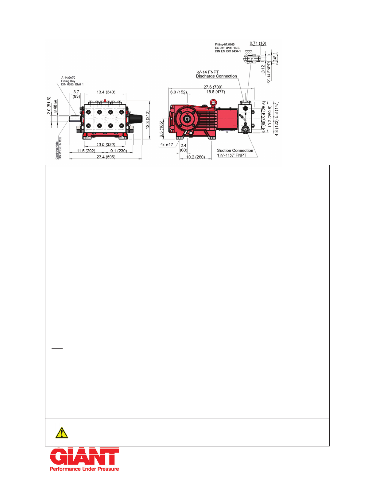
8.2 Suction and Discharge Valves
Loosen screws (58C).
Take plugs (58) out of valve casing with two
screws.
Take out tension spring (57) and complete valve
(51, 52) using either tool (07662) or stud bolt
(size M16).
Valve seats (51C and 52C) are pressed out of
spacer pipe (51F, 52F) by hitting the valve plate
(51D, 52D) with a bolt.
Check surfaces of valve plate, valve seat,
O-rings (51B, 58A) and support ring (58B) for
damage.
Replace worn parts.
When reassembling, the suction valve
seat (51C) is 1 mm smaller in diameter
than the discharge valve seat (52C).
Suction valve seats are marked “S” and
always have to be installed rst.
Discharge valve seats are marked “P” and are
always to be installed on top of suction valve.
Plugs (58) are to be tensioned down evenly
with screws (58C) and crosswise to the required
torque.
8.3 Seals and Plunger
Remove nuts (49A) and pull off pump head.
Take off cover plate (30).
Using a size 27 open-end wrench, separate
plunger (36) from crosshead (25).
Don’t loosen the 3 plungers (36)
before the valve casing has been
removed.
Otherwise the plunger (36) could hit
against the spacer pipe (51F) when the pump is
being turned.
Remove seal sleeve (38) together with the
plunger (36) from the crankcase guides (use
ring groove as an aid).
Take seal case (39) out of seal sleeve (38).
Remove plunger (36) from seal sleeve.
Take pressure spring (40), support disc (41),
seal unit (42/43/44) and pressure ring (45) out of
the seal sleeve.
Remove leakage gasket (38B) from serrated pin
(38A) on the seal sleeve (38).
Take-off circlip (48) using a clipring pliers, pull
out spacer disc (47).
Lever grooved seal (46) out of the seal sleeve
(38).
Check plunger surface (36), seal unit (42/43/44),
leakage gasket (38B) and seal ring (46).
Check O-rings (38C/39A) on the seal case (39)/
seal sleeve (38).
Replace worn seals.
The Ø3.2mm bore of the leakage
gasket (38B) must be inserted directly
on to the serrated pin (38A) of the seal
sleeve (38A).
The leakage gasket (38B) must be tted to the
seal sleeve (38) so that the bevelled surface of
the gasket (38B) faces outwards.
When exchanging worn plunger, attention must
be paid that the centre bore and front surface of
the crosshead (25) are free of dirt and damage.
Thread new plunger carefully through oiled
seals in seal sleeve.
Coat thread of new plunger lightly with suitable
bonding agent.
Then insert seal sleeve with plunger into
crankcase guide. Drive Crankshaft until plunger
with crosshead (25) pushes against plunger
(36).
Tighten plunger (36) to the required torque using
a size 27 torque wrench.
Mounting Valve Casing:
Clean surfaces of seal sleeves (38) in gear box
and sealing surfaces of valve casing.
Push valve casing carefully onto O-rings of seal
case and centring studs (50A).
Tighten nuts (49A) to the required torque.
If required, supplementary assembly
instructions can be requested from Giant
Industries.