manuals.online logo
Brands
  1. Home
  2. •
  3. Brands
  4. •
  5. Giant
  6. •
  7. Water Pump
  8. •
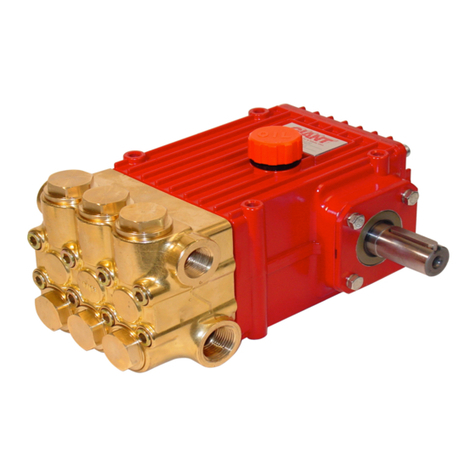
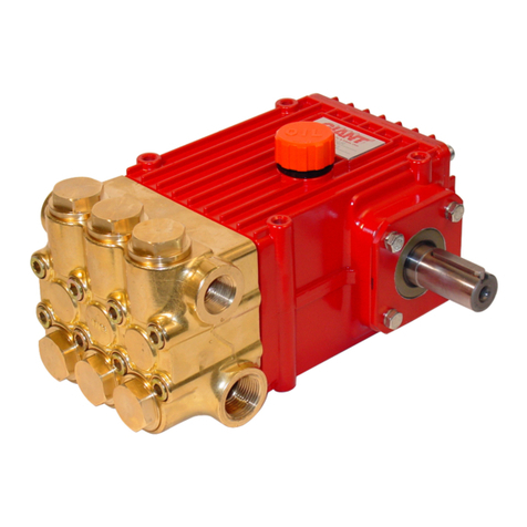
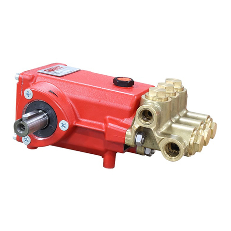
  9. Giant P435-5121 User manual

Giant P435-5121 User manual

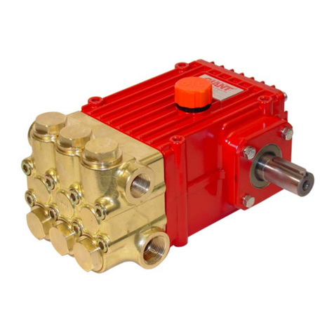
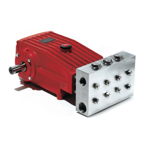
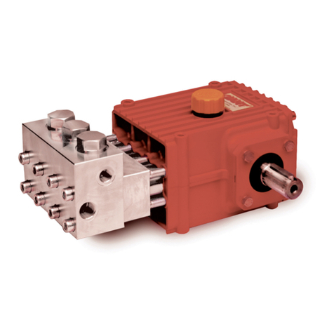
Triplex Ceramic Plunger Pump
Operating Instructions
Repair and Service Manual
Models
P435-5121/P450-5121
Corrosion-Resistant Pump with Te on Seals/Viton O-Rings
Updated 08/23
Contents:
Performance Information: pages 2-3
Installation Instructions: page 3
Exploded View page 4
Parts List / Kits page 5
Repair Instructions: page 6
Pump mounting selection Guide: page 7
Recommended Spare Parts List: page 7
Torque Specs: page 7
Dimensions: back page
Warranty Information back page
2
U.S. ............................................(Metric)
Inlet Pressure.......................................................90 PSI....................................(6.2 bar)
Temperature of Pumped Fluids............................Up to 160 oF .........................(70 oC)
Inlet Ports............................................................................................................2 x 3/4” BSP
Discharge Ports ..................................................................................................2 x 1/2” BSP
Shaft Rotation .....................................................................................................Top of pulley towards manifold
Crankshaft Diameter ...........................................................................................(28 mm)
Key Width............................................................................................................(8 mm)
Shaft Mounting....................................................................................................Either side (specify when ordering)
Weight ..................................................................36.5 lbs .................................(16.6 kg)
Crankcase Capacity.............................................30 .oz. .................................(0.89 liters)
1. Performance
P435-5121 and P450-5121
Max. Flow Pressure Max. Speed Power Req’d.
Plunger
Diameter Stroke
Model GPM PSI RPM BHP In. In.
P450-5121 5.5 5075 1450 19.2 0.71 0.79
P435-5100 6.6 3625 1450 16.6 0.71 0.94
Max. Flow Pressure Max. Speed Power Req’d.
Plunger
Diameter Stroke
Model LPM Bar RPM kW mm mm
P450-5100 20.8 350 1450 14.3 18 20
P435-5100 25.0 250 1450 12.4 18 24
U.S. Measurements
Metric Measurements
Common Specications
SPECIAL NOTE:
P450-5121:
The theoretical gallons per revolution (gal/rev) is
0.00455. To nd specic outputs at various RPM, use
the formula: GPM = 0.00455 x RPM
P430-5121:
The theoretical gallons per revolution (gal/rev) is
0.00379. To nd specic outputs at various RPM, use
the formula: GPM = 0.00379 x RPM
Performance data for intermittent operation, data for continuous operation on request.
For information on intermittent operation and calculating of the performance data, see the Giant Pumps
assembly instructions.
NPSHR / Inlet pressure
Required NPSH refers to water at 60 °F (20 °C) at max. permissible pump speed.
Maximum inlet pressure: 145 PSI (10 bar)
Level of noise emission
Emission sound pressure level: ≤ 88 dB(A)
3
1.3 Horsepower Information
Horsepower ratings shown are the power requirements for the pump. Gas engine power outputs must be
approximately twice the pump power requirements shown above.
We recommend that a 1.15 service factor be specied when selecting an electric motor as the power source.
To compute specic pump horsepower requirements, use the following formula: (GPM X PSI) / 1450 = HP
2. Fields of application
The fields of application of these pump types correspond to the specifications in the assembly instructions
Giant Pumps.
3. Ambient conditions
Ambient temperature: 41 °F < T Amb. < 86 °F
Ambient temperature: 5 °C < T Amb. < 30°C
4. Oil lling
• Filling quantity: 30.4 . oz. (0.9 l)
• Quality: Industrial gear oil ISO VG 220 or automotive gear oil SAE 90 GL4 (Giant’s p/n 01154)
• Intervals: rst oil change after 50 operating hours then every 500 operating hours, but at the latest after
12 months
5. Installation/ Putting into Operation
5.1 To Turn Drive Shaft to the Other Side
Remove the valve casing.
Turn the seal adaptors (20) by 180° also so that the leakage holes are underneath.
Remount valve casing rotated by 180°.
Interchange plug (5B) and oil dipstick (2) with each other.
Turn crankcase cover (3) by 180°.
5.2 Direction of pump rotation
When looking at crankshaft with valve casing mounted on left-hand side, counterclockwise direction of
rotation.
When looking at crankshaft with valve casing mounted on right-hand side, clockwise direction of rotation.
5.3 Suction line lter
Recommended mesh size 150 μm.
6. Operation
For information, see assembly instructions Giant Pumps.
P435-5121 and P450-5121
P435-5121
HORSEPOWER REQUIREMENTS
RPM GPM 2000
PSI
2500
PSI
3000
PSI
3625
PSI
920 4.2 5.8 7.2 8.7 10.5
1050 4.8 6.6 8.3 9.9 12.0
1185 5.4 7.4 9.3 11.2 13.5
1315 6.0 8.3 10.3 12.4 15.0
1450 6.6 9.1 11.4 13.7 16.5
P450-5121
HORSEPOWER REQUIREMENTS
RPM GPM 2000
PSI
3000
PSI
4000
PSI
5000
PSI
800 3.0 4.1 6.2 8.3 10.3
933 3.5 4.8 7.2 9.7 12.1
1066 4.0 5.5 8.3 11.0 13.8
1200 4.5 6.2 9.3 12.4 15.5
1450 5.5 7.6 11.4 15.2 19.0
4
P435-5121 and P450-5121 Exploded View
5
ITEM PART DESCRIPTION QTY.
1 08377 Crankcase 1
2 08378 Oil Fill Plug with Gasket 1
3 06479 Crankcase cover 1
3A 07186 Oil Sight Glass w/ Gasket 1
4 08380 O-Ring 1
5 07109-0400 Oil Drain Plug 1
5A 07182 Gasket for Oil Drain Plug 1
5B 08092-0100 Plug with Gasket 1
6 01010-0100 Screw 4
6A 01011-0400 Spring Washer 4
7 04739 Bearing Cover, Open 1
8 05291 Bearing Cover, Closed 1
8A 05292 Shim 1-6
9 01016 O-Ring 2
10 07114-0100 Screw with Washer 8
10A 01011-0400 Spring Washer 8
11 07459 Radial Shaft Seal 1
12 05350 Bearing 2
13 04741 Crankshaft (P435-5121) 1
13 04740 Crankshaft (P450-5121) 1
13A 04742 Spacer Ring 3
14 08091 Fitting Key 1
15 08390 Connecting Rod Assembly 3
15B 05349 Screw 3
15C 05348 Washer 3
16 05575 Plunger Assy. Items 16A-16G 3
16A 08384-0600 Plunger Base 3
P435-5121 and P450-5121 Parts List
ITEM PART DESCRIPTION QTY.
16B 08397 Plunger Pipe 3
16D 08399-0100 Tensioning Screw 3
16E 07023-0001 O-Ring 3
16F 07203 Backup Ring 3
16G 07161-0100 Copper Washer 3
16H 06931 Oil Scraper 3
17 06790 Crosshead Pin 3
19 05444 Oil Seal 3
20 05534-0100 Seal Case 3
21 07266-0001 O-Ring, Viton 3
23 08087-0020 V-Sleeve, 18mm, Teon 6
24 07929 Pressure Ring 3
25 06804 Weep Return Ring 3
26 08470-5000 Manifold 1
27A 05578 Valve Assembly (27-31) 6
27 05576 Valve Seat 6
28 05577 Valve Plate 6
29 07906-0100 Valve Spring 6
30 07907 Valve Spring Retainer 6
31 07770-0001 O-Ring, Viton 6
32 08406-0100 Plug 6
33 06015-0001 O-Ring, Viton 6
34 08396-0100 Cap Screw 8
36 12250 Plug, 1/2” BSP 1
36A 06807 Steel Ring 1
36B 13150-0100 Plug, 3/4”, S.S. 1
36C 06808 Steel Seal Ring 1
Oil Seal Kit
# 09641
Item Part # Description Qty.
19 05444 Oil Seal 3
Valve Assembly Kit
# 09646-0001
Item Part # Description Qty.
27A 05578 Valve Ass’y, Complete 6
33 06015-0001 O-Ring 6
Plunger Packing Kits
# 09141-0021
Item Part # Description Qty.
21 07266-0001 O-Ring 3
23 08087-0020 V-Sleeve,18mm 6
24 07929 Pressure Ring 3
P435-5121 and P450-5121 Repair Kits
6
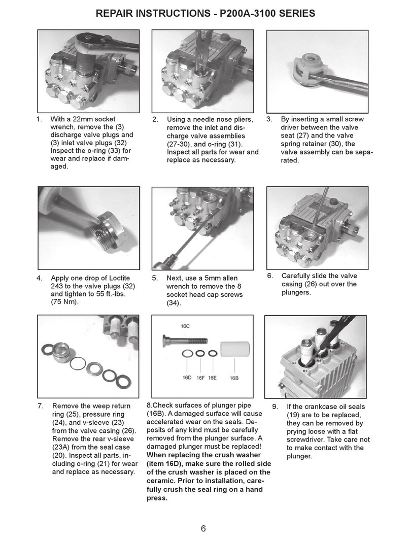
8. Maintenance and Servicing
For the type of threadlocker used and the required
tightening torques, observe the table in the
exploded view.
8.1 Special tools required
The following special tools are required for
assembly:
- Fitting Sleeve (Tool-11)
- Pull-out tool size 2 (Ø20mm)
8.2 Suction and Discharge Valves
Screw out plugs (32) with a 12-point socket
wrench.
Check suction and discharge valves that are
under the plugs by taking out the valves with a
pair of  at tongs and then taking them apart.
Examine valve plate (28) and valve seat (27).
Check O-rings (31/33) and replace if necessary.
Wet O-rings thinly with silicone grease or mineral
oil and insert carefully.
Tighten the plugs to the required torque.
Take care to reassemble in correct sequence.
8.3 Seals and Plunger pipe
Loosen screws (34) and remove valve casing (26)
by pulling it off over the plungers.
Remove seal adaptors (20) out of the valve casing
(26).
Remove drip-return ring (25), support ring (24),
grooved seal (23) and out of valve casing (26).
Remove grooved seal (23) out of seal adaptor
(20).
Wet new seals and O-rings thinly with silicone
grease or mineral oil and insert carefully.
Pay attention to the installation position of the
seals.
Check O-rings (21) and replace if necessary.
The grooved seal (23) or respectively
grooved seal pack (23) on the high-
pressure side is to be  tted carefully into
the valve casing (26) using a  tting
sleeve (Tool-11).
REPAIR INSTRUCTIONS - P435-5121 and P450-5121
Alternatively, the seal can also be carefully  tted
into the valve casing using a screwdriver.
Under no circumstances must the seal surface in
the valve casing or the seal lip be damaged.
Check plunger surfaces (16).
Damaged surfaces cause hard wear on seals.
Lime deposits or similar on the plunger must be
removed.
Plunger surface must not be damaged in
the process.
In the case of lime deposits in the pump,
care must be taken that the drip-return
bores in parts (25) and (26) ensure trouble-free
drip-return.
If the plunger pipe (16B) is worn out, loosen
tension screw (16D) and remove together with
plunger pipe.
Check and clean contact surface on plunger (16A),
check oil scraper(16H),  t new plunger pipe.
Cover thread of tension screw (16D) with a thin
coat of thread locker and tighten carefully to the
required torque.
Under no circumstances should thread-
locker get between the plunger pipe (16B)
and the centring neck on the plunger
(16A). Tensioning of the plunger pipe due
to eccentric tightening of the tensioning
screw or due to dirt or damage to the contact
surface can lead to breakage of the plunger pipe.
When assembling, tighten the screws (34) to the
required torque.
642 7
8135
If required, supplementary assembly
instructions can be requested from the
manufacturer Giant Industries, Inc.
7
Pump Mounting Selection Guide
Bushings
07175 - 28 mm Tapered H Bushing
Pulley & Sheaves
01055 - 7.75” Cast Iron - 2 gr. - AB Section
01062 - 7.75” Cast Iron - 2 gr. - AB Section
Rails
07358 - Plated Steel Channel Rails
(L=9.18”x W=1.88”x H=3.00”)
Preventative Maintenance Check List & Recommended Spare Parts List
Check Daily Weekly 50 hrs
Every
500 hrs
Every
1500 hrs
Every
3000 hrs
Oil Level/Quality X
Oil Leaks X
Water Leaks X
Belts, Pulley X
Plumbing X
Recommended Spare Parts
Oil Change p/n 01154 X X
Seal Spare Parts (1 kit/pump)
(see page 5 for kit list)
X
Oil Seal Kit (1 kit/pump)
(see page 5 for kit list)
X
Valve Spare Parts (1 kit/pump)
(see page 5 for kit list)
X
P435-5121 and P450-5121 PUMP TORQUE SPECIFICATIONS
Position Item # Description Thread Size Lubrication Info Torque Amount
3A 07186 Oil Sight Glass w/Gasket 1” BSP Loctite 5910 106 in.-lbs. (12 Nm)
5 07109-0400 Oil Drain Plug 1/2” BSP 59 ft.-lbs. (80 Nm)
5B 08092-0100 Plug with Gasket 3/4” BSP 59 ft.-lbs. (80 Nm)
601010-0100 Screw M8 110.6 in.-lbs. (12.5 Nm)
10 07114-0100 Screw with Washer M8 132 in.-lbs. (15 NM
15 08390 Screw with Washer M6 97 in.-lbs. (11 Nm)
16D 08399-0100 Tensioning Screw M8 Loctite 243 199 in.-lbs. (22.5 Nm)
16G 07161-0100 Copper Washer Loctite 577
(both sides)
32 08406-0100 Plug M 24 x 1.5 Loctite 243 110.6 ft.-lbs. (150 Nm)
34 08396-0100 Cap Screw M10 29.5 ft.-lbs. (40 Nm)
GIANT INDUSTRIES, INC., 900 N. Westwood Ave., Toledo, Ohio 43607
PHONE (419) 531-4600, FAX (419) 531-6836, www.giantpumps.com
 Copyright 2023 Giant Industries, Inc.
08/23 P435-5121_P450-5121.indd
P435-5121 and P450-5121 Pump Dimensions - Inches (mm)
GIANT INDUSTRIES LIMITED WARRANTY
Giant Industries, Inc. pumps and accessories are warranted by the manufacturer to be free from defects in
workmanship and material as follows:
1. Five (5) years from the date of shipment for all pumps used in portable pressure
washers with NON-SALINE, clean water applications.
2. Two (2) years from the date of shipment for Giant pumps used in car wash
applications.
3. One (1) year from the date of shipment for all other Giant industrial and consumer
pumps.
4. Six (6) months from the date of shipment for all rebuilt pumps
5. Ninety (90) days from the date of shipment for all Giant accessories.
This warranty is limited to repair or replacement of pumps and accessories of which the manufacturer’s
evaluation shows were defective at the time of shipment by the manufacturer. The following items are NOT
covered or will void the warranty:
1. Defects caused by negligence or fault of the buyer or third party.
2. Normal wear and tear to standard wear parts.
3. Use of repair parts other than those manufactured or authorized by Giant.
4. Improper use of the product as a component part.
5. Changes or modi cations made by the customer or third party.
6. The operation of pumps and or accessories exceeding the speci cations set forth
in the Operations Manuals provided by Giant Industries, Inc.
Liability under this warranty is on all non-wear parts and limited to the replacement or repair of those products
returned freight prepaid to Giant Industries which are deemed to be defective due to workmanship or failure of
material. A Returned Goods Authorization (R.G.A.) number and completed warranty evaluation form is required
prior to the return to Giant Industries of all products under warranty consideration. Call (419)-531-4600 or fax
(419)-531-6836 to obtain an R.G.A. number.
Repair or replacement of defective products as provided is the sole and exclusive remedy provided hereunder
and the MANUFACTURER SHALL NOT BE LIABLE FOR FURTHER LOSS, DAMAGES, OR EXPENSES,
INCLUDING INCIDENTAL AND CONSEQUENTIAL DAMAGES DIRECTLY OR INDIRECTLY ARISING FROM
THE SALE OR USE OF THIS PRODUCT.
THE LIMITED WARRANTY SET FORTH HEREIN IS IN LIEU OF ALL OTHER WARRANTIES OR
REPRESENTATION, EXPRESS OR IMPLIED, INCLUDING WITHOUT LIMITATION ANY WARRANTIES
OR MERCHANTABILITY OR FITNESS FOR A PARTICULAR PURPOSE AND ALL SUCH WARRANTIES
ARE HEREBY DISCLAIMED AND EXCLUDED BY THE MANUFACTURER.
WARNING: This product might contain a chemical known to the State of California to cause cancer,
and birth defects or other reproductive harm.
For more information go to www.P65Warnings.ca.gov

This manual suits for next models

1

Other Giant Water Pump manuals

Giant GP5136-5100 Instruction Manual

Giant

Giant GP5136-5100 Instruction Manual

Giant LP650 User manual

Giant

Giant LP650 User manual

Giant GP7532GB User manual

Giant

Giant GP7532GB User manual

Giant GP8055 User manual

Giant

Giant GP8055 User manual

Giant MP Series User manual

Giant

Giant MP Series User manual

Giant LP122A Series Service manual

Giant

Giant LP122A Series Service manual

Giant P435B User manual

Giant

Giant P435B User manual

Giant P46W-HK User manual

Giant

Giant P46W-HK User manual

Giant LP200-SS User manual

Giant

Giant LP200-SS User manual

Giant MP Series User manual

Giant

Giant MP Series User manual

Giant P532 User manual

Giant

Giant P532 User manual

Giant GP8055-Brine User manual

Giant

Giant GP8055-Brine User manual

Giant GP5128GB Series Instruction Manual

Giant

Giant GP5128GB Series Instruction Manual

Giant P450-5100 User manual

Giant

Giant P450-5100 User manual

Giant MP Series User manual

Giant

Giant MP Series User manual

Giant MP4130-3100 User manual

Giant

Giant MP4130-3100 User manual

Giant GP8135 Setup guide

Giant

Giant GP8135 Setup guide

Giant P200 Series User manual

Giant

Giant P200 Series User manual

Giant LP301A-5100 Instruction Manual

Giant

Giant LP301A-5100 Instruction Manual

Giant CP460 User manual

Giant

Giant CP460 User manual

Giant GP7545GB User manual

Giant

Giant GP7545GB User manual

Giant P435-5100 User manual

Giant

Giant P435-5100 User manual

Giant MP4124-SWS User manual

Giant

Giant MP4124-SWS User manual

Giant SP200HT User manual

Giant

Giant SP200HT User manual

Popular Water Pump manuals by other brands

Flotec FP400C installation instructions

Flotec

Flotec FP400C installation instructions

variolux V-RFP 400 Original instructions

variolux

variolux V-RFP 400 Original instructions

Greentek BUNKER DRAINER Operator's manual

Greentek

Greentek BUNKER DRAINER Operator's manual

SOLIDSVAC SV10-AIR FOX Operation manual

SOLIDSVAC

SOLIDSVAC SV10-AIR FOX Operation manual

Oase 90 operating instructions

Oase

Oase 90 operating instructions

Glentronics Cast Iron CIS-33V Instruction manual & safety warnings

Glentronics

Glentronics Cast Iron CIS-33V Instruction manual & safety warnings

Bestway FLOWCLEAR 58386 manual

Bestway

Bestway FLOWCLEAR 58386 manual

AquaIllumination Nero 3 quick start guide

AquaIllumination

AquaIllumination Nero 3 quick start guide

ACUDOR DW5015 manual

ACUDOR

ACUDOR DW5015 manual

ITT Flygt 5150.350 Installation, operation and maintenance manual

ITT

ITT Flygt 5150.350 Installation, operation and maintenance manual

Waterous VPE operation & maintenance

Waterous

Waterous VPE operation & maintenance

Mui Scientific Rapid Barostat Bag user manual

Mui Scientific

Mui Scientific Rapid Barostat Bag user manual

KC 23.580 manual

KC

KC 23.580 manual

Titan Epic 660HPX owner's manual

Titan

Titan Epic 660HPX owner's manual

AQUASYSTEM APDX1-25 Operation manual

AQUASYSTEM

AQUASYSTEM APDX1-25 Operation manual

aquanique WP1300UV manual

aquanique

aquanique WP1300UV manual

NUK BP7 Series operating instructions

NUK

NUK BP7 Series operating instructions

Stenner Pumps S Series Installation and maintenance manual

Stenner Pumps

Stenner Pumps S Series Installation and maintenance manual

manuals.online logo
manuals.online logoBrands
  • About & Mission
  • Contact us
  • Privacy Policy
  • Terms and Conditions

Copyright 2025 Manuals.Online. All Rights Reserved.