manuals.online logo
Brands
  1. Home
  2. •
  3. Brands
  4. •
  5. Giant
  6. •
  7. Water Pump
  8. •
  9. Giant P470H User manual

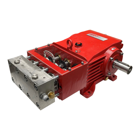
Giant P470H User manual

Contents:
Installation Instructions: page 2
Pump Specications: page 3
Exploded View: page 4
Parts List / Kits: page 5
Torque Specications page 5
Repair Instructions: pages 6-7
Dimensions: back page
Warranty Information: back page
Triplex Ceramic
Plunger Pump
Operating Instructions/
Repair and Service Manual
Model
P470H
Hydraulic Drive Pump
Updated 04/22
2
INSTALLATION INSTRUCTIONS
Safety Rules
A safety valve is to be installed in accordance
with the guidelines for liquid spraying units
so that the admissible operating pressure
cannot be exceeded by more than 10%. Pump
operation without a safety valve as well as
any excess in temperature or speed limits
automatically voids the warranty.
When the pump is in operation, the drive shaft
end and the coupling must be enclosed by a
protective cover or a coupling bell.
Pressure in the discharge line and pump must
be at zero before any maintenance to the pump
takes place. Close suction line. Disconnect
fuses to ensure that the driving motor does not
get switched on accidentally.
Make sure that all parts on the pressure side
of the unit are vented before starting the pump.
In order to prevent air, or an air-water mixture
being absorbed and to prevent cavitation
occuring, the pump NPSHR suction head and
water temperature must be respected.
Cavitation and/or compression of gases lead
to uncontrollable pressure kicks which can ruin
pump and unit parts and also be dangerous to
the operator or anyone standing nearby.
Giant plunger pumps are suitable for pumping
clean water and other non-agressive or non-
abrasive media with a specic weight similar to
water.
Before pumping other liquids - especially
inammable, explosive and toxic media - the
pump manufacturer must be consulted with
regard to the resistance of the pump material.
It is the responsibility of the equipment
manufacture and/or operator to ensure that all
pertinent safety regulations are adhered to.
Required NPSH refers to water (specic
weight 1kg/dm3, viscosity 1°E) and maximum
premissible pump revolutions.
Operation and Maintenance
Check oil level prior to starting and ensure
trouble-free water supply.
Important! If there is a danger of frost, the
water in the pump and in the pump ttings
(particularly the unloader valve) must be
emptied. The second discharge port can be
used and the pump run “dry” for 1-2 minutes for
this purpose.
Oil: Use only 27.1 uid ounces (0.8 liters) of
ISO VG 220 GL4 (e.g. Aral Degol BG220) or
SAE 90 GL4 gear oil (Giant p/n 01154).
Initial oil change after 50 operating hours and
then every 500 hours,after 1 year if used less.
Caution: When operating in damp places or
with high temperature uctuations, oil must
be changed immediately [should condensate
(frothy oil) occur in the gear box].
NPSH values must be observed.
Maximum input pressure 145 PSI (10 bar),
maximum suction head -4.35 PSI (-0.3 bar).
Make sure that suction pulsation is su󰀩ciently
dampened - water column resonance must be
avoided.
Important! If the pump is not used for a long
period of time, it is possible the seals (23) could
become hard or brittle thus causing the pump to
leak when put into operation.
If this is the case, we recommend these seals
be replaced every 4 years.
3
Specications Model P470H
Volume ..........................................................................Up to 18.4 GPM....................................... 69.7 L/min
Discharge Pressure.......................................................Up to 2030 PSI .............................................140 Bar
Max. Inlet Pressure .......................................................-4.35 to 145 PSI ..................................-0.3 to 10 bar
Power Required ............................................................25.7 BHP ..................................................... 19.2 kW
Maximum Crankshaft Rotation Speed ..................................................................................Up to 1450 RPM
Stroke............................................................................0.94” ............................................................... 24mm
Crankcase Oil Capacity.................................................27.1 .oz.................................................... 0.8 Liters
Temperature of Pumped Fluids .....................................Up to 160 oF.................................................... 70 oC
Plunger Diameter ..........................................................1.18” ............................................................... 30mm
Inlet Ports ........................................................................................................ (1) x 1” BSP* & (2) x 3/4” BSP
Discharge Ports........................................................................................................................... (2) 3/4” BSP
Crankshaft Bore .................................................................................SAE 2B or SAE 4B 13T 16/32 Spline**
Shaft Rotation ..................................................................................................................... Towards uid end
Weight ...........................................................................39.7 lbs............................................................ 18 kg
NPSHR..........................................................................32.8 feet of head ...................... 10.0 meters of head
* Recommended for inlet connection.
** J498b 30° Class 5
U.S. METRIC
Consult the factory for special requirements that must be met if the
pump is to operate beyond one or more of the limits specied above.
RPM GPM 500 PSI 750 PSI 1000 PSI 1500 PSI 2030 PSI
1000 12.7 4.4 6.6 8.8 13.1 17.8
1100 14.0 4.8 7.2 9.7 14.5 19.6
1200 15.2 5.2 7.9 10.5 15.7 21.3
1300 16.5 5.7 8.5 11.4 17.1 23.1
1450 18.4 6.3 9.5 12.7 19.0 25.8
P470 HORSEPOWER REQUIREMENTS
NOTE:
In order to drive the pump from the side opposite the present shaft extension, simply remove the
valve casing from the crankcase and rotate the pumps 180 degrees to the desired position. Be
certain to rotate the seal case (item #20) as well, so that the weep holes are down at the six o’clock
position. Exchange the oil ll and the oil drain plugs, also. Refer to the repair instructions as neces-
sary for the proper assembly sequence.
Horsepower Ratings:
Horsepower ratings shown are the power requirements for the pump. Gas engine power outputs must
be approximately twice the pump power requirements shown above. We recommend that a 1.15
service factor be specied when selecting an electric motor as the power source. To compute specic
pump horsepower requirements, use the following formula: (GPM X PSI) / 1450 = HP
For the Application of a Hydraulic Motor:
To Determine the Torque of a Hydraulic Motor -- (GPM x PSI x 36.77) / RPM = Torque (in-lbs)
4
Exploded View - P470H
5
ITEM PART DESCRIPTION QTY.
1 08377 Crankcase 1
2 08378 Oil Fill Plug with Gasket 1
3 06479 Crankcase Cover 1
3A 07186 Oil Sight Glass w/Gasket 1
4 08380 O-Ring 1
5 07109 Oil Drain Plug 1
5A 06015 O-Ring 1
5B 08092 Plug with Gasket 1
6 01010 Screw 4
6A 01011-0400 Spring Washer 4
7 04739 Bearing Cover, Open 1
7A 03266 Motor Flange 1
7B 03297 Plug, M12 x 1 1
8 05291 Bearing Cover, Closed 1
8A 05292 Shim, 0.1 mm 1-3
9 01016 O-Ring 2
10 07114 Hexagon Socket Screw 4
10A 07774 Hexagon Socket Screw 4
11 07459 Radial Shaft Seal 1
12 05350 Bearing 2
13 03268 Crankshaft 1
13A 04742 Spacer Ring 1
14 03269 Magnet 1
15 08390 Connecting Rod Assembly 3
15B 05249 Connecting Rod Screw 3
15C 05348 Adapter Sleeve 3
16 05933 Plunger Assembly 3
16A 05352 Plunger Base 3
16B 06927 Plunger Pipe 3
16D 08399 Tension Screw 3
16E 07023 O-Ring 3
P470H PARTS LIST
ITEM PART DESCRIPTION QTY.
16F 07203 Support Ring 3
16G 07258 Copper Gasket 3
17 06790 Crosshead Pin 3
19 08366 Oil Seal 3
20 06928 Seal Adapter 3
20A 08059 O-Ring 3
21 06929 Seal Case 3
21A 07150 O-Ring 6
22 06930 Valve Holder 3
23 06931* Grooved Seal 6
24 06932 Support Ring 3
25 06933 Intermediate Casing 1
25B 02009 O-Ring 2
26 06935 Valve Casing 1
27A 04365 Valve Assembly 6
27 06937 Valve Seat 6
28 06938 Valve Plate 6
29 06959 Valve Spring 6
30 06939 Valve Spring Retainer 6
31 07212 O-Ring 6
32 08373 Plug 3
33 07214 O-Ring 3
34 06494 Cap Screw 8
36 07703 Plug, 3/4” BSP 3
36A 04529 Copper Ring 3
*Important! If the pump is not used for a long period
of time, it is possible the seals (23) could become hard
or brittle thus causing the pump to leak when put into
operation. If this is the case we recommend these seals
be replaced every 4 years.
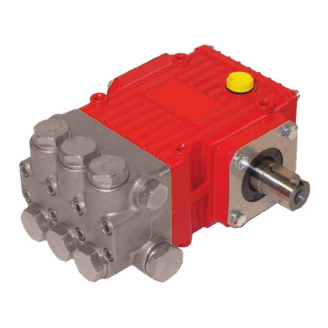
Plunger Packing Kit, #09565
Item Part # Description Qty.
20A 08059 O-Ring 3
21A 07150 O-Ring 6
23 06931 Grooved Seal 6
24 06932 Support Ring 3
25B 02009 O-Ring 2
Valve Assembly Kit, #09566
Item Part # Description Qty.
27A 04365 Valve Assembly 6
31 07212 O-Ring 6
33 07214 O-Ring 3
Oil Seal Kit, #09306
Item Part # Description Qty.
19 08366 Oil Seal 3
P470H REPAIR KITS
P470H Torque Specications
Item Part # Description Lubrication Info Torque Amount
3A 07186 Oil Sight Glass/Gasket Loctite 5910 106 in.-lbs. (12 Nm)
5 07109 Plug 59 ft.-lbs. (80 Nm)
5B 08092 Plug w/Gasket 59 ft.-lbs. (80 Nm)
6 01010 Screw 110 in.-lbs. (12.5 Nm)
10 07114 Screw with Washer 132 in.-lbs. (15 Nm)
10A 07774 Hexagon Socket Screw 132 in.-lbs. (15 Nm)
15 08390 Connecting Rod Screw 97 in.-lbs. (11 Nm)
16D 08399 Tension Screw Loctite 243 21 ft.-lbs. (28 Nm)
32 08373 Plug Loctite 243 125 ft.-lbs. (170 Nm)
34 06494 Cap Screw Lightly Oil Threads 30 ft.-lbs. (40 Nm)

Other Giant Water Pump manuals

Giant Triplex Ceramic Plunger Pump LP350 User manual

Giant

Giant Triplex Ceramic Plunger Pump LP350 User manual

Giant GP7622 User manual

Giant

Giant GP7622 User manual

Giant GXR Series User manual

Giant

Giant GXR Series User manual

Giant P400 Series User manual

Giant

Giant P400 Series User manual

Giant GP5132 Instruction Manual

Giant

Giant GP5132 Instruction Manual

Giant GP8055 User manual

Giant

Giant GP8055 User manual

Giant P205 Repair and User manual

Giant

Giant P205 Repair and User manual

Giant LP301A User manual

Giant

Giant LP301A User manual

Giant P220-3000 User manual

Giant

Giant P220-3000 User manual

Giant P200A-3100 Series Repair and User manual

Giant

Giant P200A-3100 Series Repair and User manual

Giant SP100HT User manual

Giant

Giant SP100HT User manual

Giant GP8135A User manual

Giant

Giant GP8135A User manual

Giant P480 User manual

Giant

Giant P480 User manual

Giant GP7145 User manual

Giant

Giant GP7145 User manual

Giant GP7545GB User manual

Giant

Giant GP7545GB User manual

Giant LP121A User manual

Giant

Giant LP121A User manual

Giant LP121A-5100 User manual

Giant

Giant LP121A-5100 User manual

Giant P420A-5100 User manual

Giant

Giant P420A-5100 User manual

Giant P450-5100 User manual

Giant

Giant P450-5100 User manual

Giant MP4130-3100 User manual

Giant

Giant MP4130-3100 User manual

Giant CP460 User manual

Giant

Giant CP460 User manual

Giant GP5136-5100 Instruction Manual

Giant

Giant GP5136-5100 Instruction Manual

Giant P435-5121 User manual

Giant

Giant P435-5121 User manual

Giant MP Series User manual

Giant

Giant MP Series User manual

Popular Water Pump manuals by other brands

Watershed Innovations HYDRAPUMP SMART FLEX Instructional manual

Watershed Innovations

Watershed Innovations HYDRAPUMP SMART FLEX Instructional manual

Graco Modu-Flo AL-5M instructions

Graco

Graco Modu-Flo AL-5M instructions

Messner MultiSystem MPF 3000 operating instructions

Messner

Messner MultiSystem MPF 3000 operating instructions

Xylem Bell & Gossett WEHT0311M Installation, operation and maintenance instructions

Xylem

Xylem Bell & Gossett WEHT0311M Installation, operation and maintenance instructions

WilTec 50739 Operation manual

WilTec

WilTec 50739 Operation manual

Franklin Electric Little Giant 555702 HRK-360S instruction sheet

Franklin Electric

Franklin Electric Little Giant 555702 HRK-360S instruction sheet

Ingersoll-Rand PD02P Series Operator's manual

Ingersoll-Rand

Ingersoll-Rand PD02P Series Operator's manual

VS ZJ Series Operating	 instruction

VS

VS ZJ Series Operating instruction

Flotec FPZS50RP owner's manual

Flotec

Flotec FPZS50RP owner's manual

SKF Lincoln FlowMaster II User and maintenance instructions

SKF

SKF Lincoln FlowMaster II User and maintenance instructions

Xylem Lowara LSB Series Installation, operation and maintenance instructions

Xylem

Xylem Lowara LSB Series Installation, operation and maintenance instructions

Water Duro Pumps DCJ500 Operating & installation instructions

Water

Water Duro Pumps DCJ500 Operating & installation instructions

Action P490 Operating instructions & parts manual

Action

Action P490 Operating instructions & parts manual

Flo King Permacore Reusable Carbon Bag Disassembly. & Cleaning Instructions

Flo King

Flo King Permacore Reusable Carbon Bag Disassembly. & Cleaning Instructions

ARO ARO PD15P-X Operator's manual

ARO

ARO ARO PD15P-X Operator's manual

Pumptec 112V Series Operating instructions and parts manual

Pumptec

Pumptec 112V Series Operating instructions and parts manual

Virax 262070 user manual

Virax

Virax 262070 user manual

Neptun NPHW 5500 operating instructions

Neptun

Neptun NPHW 5500 operating instructions

manuals.online logo
manuals.online logoBrands
  • About & Mission
  • Contact us
  • Privacy Policy
  • Terms and Conditions

Copyright 2025 Manuals.Online. All Rights Reserved.