manuals.online logo
Brands
  1. Home
  2. •
  3. Brands
  4. •
  5. Giant
  6. •
  7. Water Pump
  8. •
  9. Giant GP7645GB User manual

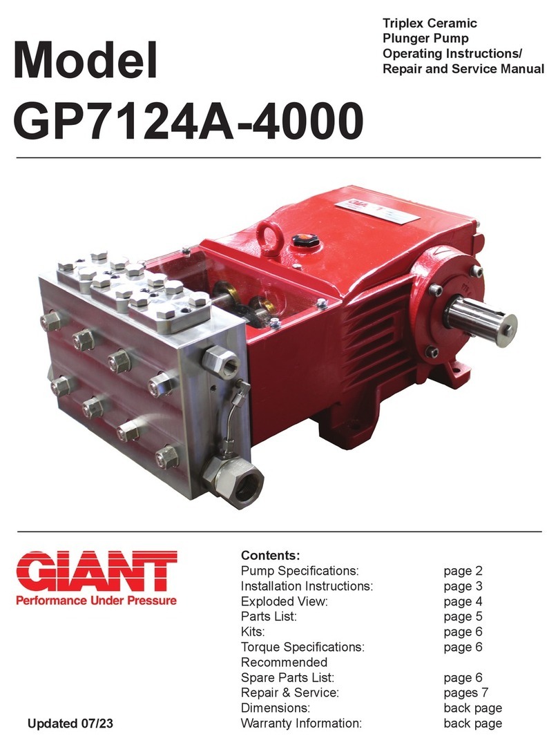
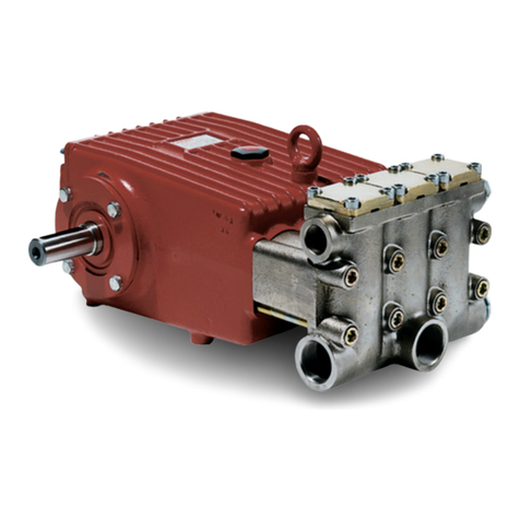
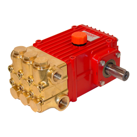
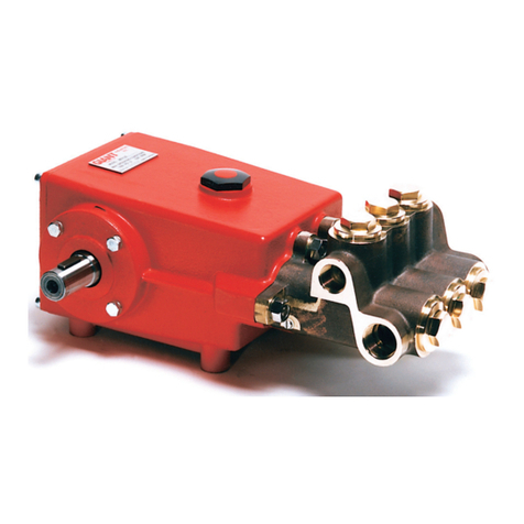
Giant GP7645GB User manual

Contents:
Installation Instructions: page 2
Pump Specications: page 3
Dimensions: page 3
Exploded View: page 4
Parts List: page 5
Kits: page 6
Torque Specications: page 6
Maintenance Information: page 6
Repair Instructions: page 7
Warranty Information: back page
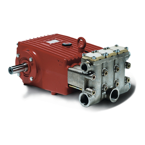
Triplex Ceramic
Plunger Pump
Operating Instructions/
Repair and Service Manual
Models
GP7645GB/GP7650GB/
GP7655GB
Gearbox Versions for Pinion Shaft Drives
Updated 03/22
2
INSTALLATION INSTRUCTIONS
NOTE: Contact Giant Industries for Service School Information. Phone: (419)-531-4600.
Operation and Maintenance
Check oil level prior to starting and ensure trouble-free water
supply.
Oil: Use only 1.6 gallons (6.0 liters) of SAE 80W-90 Industrial
Gear Lube Oil (Giant’s p/n 01154).
IMPORTANT! If the pump is mounted on a vehicle with the
possibility of unlevelness and/or the pump speed is between
300 & 500 RPM, the volume of oil should be 2 gallons (7.5
liters). To check, put the oil dipstick in the bore situated next to
the eye bolt.
Initial change after 50 hours and then after every 500 operating
hours. If used less than this, change once per year.
IMPORTANT! When operating in humid areas (or areas
with large temperature uctuations, the oil must be changed
immediately (if condensate or frothy oil occurs in the
crankcase).
IMPORTANT! We recommend that both inlet ports be used in
order to ensure cavitation-free operation and optimal suction
conditions. If only one connection is use, a safety margin of 3
feet (1 meter) has to be added to the required NPSH.
IMPORTANT! The GP7645GB, GP7650GB and GP7655GB
pumps have a black arrow on the reduction gear, which shows
the preferred direction of rotation. The pump can be delivered
either with the gear on the left side or right side (when facing
the front of the pump), which eases planning assembled units
with regard to the desired direction or rotation. In either case,
the larger gear wheel must rotate towards the front-end of
the pump.
The preferred/optimal direction of rotation ensures that the oil
is correctly splashed on the crosshead guides via the motion
of the connecting rods, which is a particular advantage where
continuous operation is involved.
The pump can also be run against the recommended direction
of the rotation if operated periodically or at reduced pressure.
If this is the case, the pump has to be run in this direction
to smoothen the bearing areas. This is done by a one-time
operation at zero pressure for at least 30 minutes; thereafter,
the pressure must be slowly increased over the next hour to
the desired maximum operating pressure. This should run-in
the pump, but you should also check the oil temperature,
which should not exceed 160 oF (71 oC).
The torque tension on the valve casing nuts (49A) is to be
checked after approximately 200 hours. Please see page 6 for
torque values.
IMPORTANT! The service life of the seals is maximized if a
minimal amount of leakage is present. A few drops of water
can drip from each plunger every minute. Leakage has to
be examine every day. If the leakage becomes excessive
(constant dripping), the plunger seals must be changed.
Safety Rules
The operating instructions must be read and adhered to
before performing any work on the pump or complete
assembled unit. No responsibility will be carried by us
for damage to materials or persons caused by improper
handling of our pumps.
Access to the pump is not allowed by unauthorized personnel.
As safety valve is to be installed in accordance with the
guidelines for liquid spraying units, so that the admissible
operating pressure cannot be exceeded by more than 10%.
Pumps operating without a safety valve as well as any excess
in temperature or speed limits automatically voids the warranty.
When the pump is in operating, the exposed shaft side, the driven
shaft side and its coupling must be covered by a protective guard.
The plunger area must also be covered by the protective plate
(30). Do not step onto the protective plate (30 ) or put weight on
it.
Before carrying out any maintenance work to the pump or pump
unit, the pressure in the discharge line and pump must be at zero.
Close o󰀨 the suction line. Disconnect fuses to ensure that the
driving motor cannot accidently get switched on. Before starting
the pump, make sure that the pump, the cooling system and all
parts on the pressure side of the unit are vented and relled with
pressure at zero.
In order to prevent air or air/water-mixture being absorbed and
cavitation occurring, the pump NPSHR (Net Positive Suction
Head Required) and water temperature must be adhered to.
Cavitation and/or compression of gases lead to
uncontrollable pressure kicks, which can ruin the pump and
unit parts and also be dangerous to the operator or anyone
standing nearby.
Giant plunger pumps are only suitable for pumping fresh clean
water.
Cooling the Gear Oil
IMPORTANT! The water input pressure must not exceed 29 PSI
(2 bar) when using the integrated system for cooling the gear oil
(standard version).
If a separate cooling circuit (maximum 29 PSI [2 bar]) is installed,
it is then possible to have an input pressure of up to maximum
145 PSI (10 bar) on the suction side.
Make sure that suction pulsation is su󰀩ciently dampened - water
column resonance must be avoided.
IMPORTANT! The pumps can be run without gear oil cooling in
continuous operation up to a power rating of 80 hp (60 kW) or
with major intermittent operation).
If operation power exceeds 80 hp (60 kW) or if continuous
operation is the case, the pump must be run with the integrated
oil cooling system. The maximum temperature of the water
being pumped and which is also fed through the cooling system
must not exceed 86 °F (30°C). The amount which is fed into the
cooling system depends on the pump speed and is approximately
1.5 GPM (5.5 L/min) at 800 RPM. The cooling water is sucked in
by one of the pumping chambers and pumped away.
IMPORTANT! The pump and cooling system must be emptied if
there is a danger of frost. Note that travel wind can cause water
in pumps tted on open vehicles to freeze even if the outside
temperature is above freezing point.
To empty the colling circuit, remove the L-joints (K11) on the
pump head (50). Blow out the circuit liquid (hoses K12) at the
joint connection (K11/K7) using compressed air.
The torque tension on the valve casing nuts (49A) is to be
checked after approximately 200 operating hours. Please refer to
the section “Maintenance” concerning the torque values.
The pump must be at zero pressure when checking the torque
tension.
3
GP7645GB, GP7650GB & GP7655GB
Gear Ratios and Input Speeds
Gear Ratio Input Speed
1.87:1 1500
2.25:1 1800
2.73:1 2200
Horsepower Ratings:
We recommend a 1.15 service factor be specied when selecting an electric motor as the power source.
To compute electric motor horsepower required, use the following formula: HP = (GPM X PSI) / 1450.
The formula to determine the horsepower required for a gas engine is: HP = (GPM X PSI) / 1150.
The formula to determine the horsepower required for a diesel engine is: HP = (GPM X PSI) / 1250.
For the Application of a Hydraulic Motor:
To Determine the Torque of a Hydraulic Motor -- (GPM x PSI x 36.77) / RPM = Torque (in-lbs)
Calculating RPM / GPM of Pump:
A pump must be connected to an electric motor or gas or diesel engine with the correct ratio of pulleys
and belts to attain the required speed and GPM. The use of a Variable Frequency Drive (VFD) may also
be used to control the RPM of a properly sized electric motor when variable ows are required.
(Max. Pump RPM / Rated Pump GPM) x Required Pump GPM = Required Pump RPM
To calculate a pulley diameter one (1) pulley diameter and the required pump RPM must be known:
(Pump RPM x Pump Pulley Diameter) / Motor RPM = Motor Pulley Diameter
(Motor RPM x Motor Pulley Diameter) / Pump RPM = Pump Pulley Diameter
Common Specications:
Inlet Pressure (w/out cooling system)........... -4.35 to 145 PSI (-0.3 to 10 Bar)
Inlet Pressure (w/cooling system)................. -4.35 to 29 PSI (-0.3 to 2 Bar)
Pinion Shaft Diameter................................... 1.38” (35mm)
Crankcase Oil Capacity................................ 2.1 Gal. (8.0 L)
Inlet Ports ..................................................... (2) 2-1/2” NPT
Discharge Ports............................................ (2) 1-1/4” NPT
Stroke ........................................................... 2.28” (58 mm)
Weight .......................................................... 474 lbs (215 kg)
Shaft Rotation............................................... Pinion Shaft Towards Back of Pump
Materials Used for GP Pumps:
Manifold ........ Nickel-Plated Spheroidal Cast Iron
Plungers ....... Solid Ceramic Oxide
Valves ........... Stainless Steel
Seals............. Nitrile with Fabric Reinforcing
Gear End ...... Spheroidal Cast Iron
GP7600GB SERIES PUMP SPECIFICATIONS
Max.
Flow
Max.
Pressure
Max.
Speed
Power
Req’d.
Max.
Temp.
Plunger
Diameter
Model GPM PSI RPM HP °F in
GP7645GB 55.5 3000 800 111 86 1.77
GP7650GB 70 2540 800 121 86 1.97
GP7655GB 84.5 2000 800 118 86 2.17
Max.
Flow
Max.
Pressure
Max.
Speed
Power
Req’d.
Max.
Temp.
Plunger
Diameter
Model L/min Bar RPM kW °C mm
GP7645GB 210 200 800 82.3 30 45
GP7650GB 265 175 800 90.0 30 50
GP7655GB 320 140 800 88.0 30 55
U.S. Specications
Metric Specications
4
Exploded View - GP7645GB, GP7650GB & GP7655GB
5
GP7645GB, GP7650GB & GP7655GB Spare Parts List
ITEM PART DESCRIPTION QTY.
1 05769 Crankcase 1
2 13000 Oil Filler Plug Assembly 1
8 07603 Oil Dip Stick 1
9 01009 O-Ring, Dip Stick 1
12 07109 Drain Plug 9
13 06272 Copper Seal for 12 9
14 05770 Bearing Cover 1
14A 12204 O-Ring 4
15 05771 Radial Shaft Seal 1
16 05772 O-Ring 2
17 05642 Inner Hexagon Screw 4
18 05039 Spring Ring 4
20 05773 Taper Roller Bearing 2
20A 05774 Fitting Disc (Shim) 1-5
21 05645 Shaft Guard Holder 1
21A 05646 Shaft Guard 1
22 04517 Crankshaft 1
23 05776 Key 1
24 05777 Connecting Rod Assy. 3
25 05778 Crosshead Assy. 3
28 05779 Crosshead Pin 3
29A 07408 Hexagon Nut 1
29B 05383 Bracket 2 f. Cooling Hose 2
29C 05662 Fixing Bracket 1
29D 05381 Bracket 2 f. Cooling Hose 1
30 07619 Cover Plate 1
30A
07225-0100
Hexagon Screw 9
30B 13136 Grommet 4
30C 05053 Disc 8
30D 13154 Cover 1
31 07623 Eye Bolt 1
32 07624 Radial Shaft Seal 3
33 07626 Seal Retainer 3
33A 07627 O-Ring for Seal Retainer 3
33B 07628 Circlip for 33 3
33C 07249 Fitting Disc 3
34 13137 Oil Scraper (Flinger) 3
36 06165A Plunger Assy. (36A-36D),
GP7645GB 3
36 07630 Plunger Assy. (36A-36D),
GP7650GB 3
36 07706 Plunger Assy. (36A-36D),
GP7655GB 3
36A 07667 Plunger Connection 3
36B 05157A Plunger Pipe, GP7645GB 3
36B 07793 Plunger Pipe, GP7650GB 3
36B 07666 Plunger Pipe, GP7655GB 3
36C 07664 Tensioning Screw
36D 07665 Copper Ring 3
38 06167 Seal Case, GP7645GB 3
38 07794 Seal Case, GP7650GB 3
38 13155 Seal Case, GP7655GB 3
38A 13156 O-Ring 3
38B 06258 O-Ring, GP7645GB & GP7650GB 3
38B 07721 O-Ring, GP7655GB 3
38C 07635 Support Ring, GP7650GB 3
39 06171 Seal Sleeve, GP7645GB 3
39 07795 Seal Sleeve, GP7650GB 3
39 13157 Seal Sleeve, GP7655GB 3
39A 13290 Grooved Ring, GP7645GB 3
39A 07796 Grooved Ring, GP7650GB 3
39A 07723 Grooved Ring, GP7655GB 3
40 07797 Support Ring, GP7655GB 3
41 13296 O-Ring, GP7645GB 3
41 05318 Support Ring, GP7650GB 3
41 13158 O-Ring, GP7655GB 3
42 13294 V-Sleeve, GP7645GB 9
42 07638 V-Sleeve, GP7650GB 6
42 07711 V-Sleeve, GP7655GB 6
43 13293 Pressure Ring, GP7645GB 3
43 07639 Pressure Ring, GP7650GB 3
43 07712 Pressure Ring, GP7655GB 3
ITEM PART DESCRIPTION QTY.
45 13297 Tension Spring, GP7645GB 3
45 07636 Pressure Spring, GP7650GB 3
49 13159 Stud Bolt 8
49A 13160 Hexagon Nut 8
50 07791 Valve Casing 1
50A 13162 Centering Stud 2
51 05594 Inlet Valve Assembly
(51A-51F) 3
51A 05595 Spring Tension Cap 3
51B 05450 Valve Spring 3
51C 05247 Valve Plate 3
51D 05596 O-Ring 3
51E 05597 Inlet Valve Seat 3
51F 05166 O-Ring 3
52 05600 Discharge Valve Assembly 3
52A 05595 Spring Tension Cap 3
52B 05450 Valve Spring 3
52C 05247 Valve Plate 3
52D 05596 O-Ring 3
52E 05598 Discharge Valve Seat 3
52F 05599 O-Ring 3
53 22610 Plug, 1/4” NPT 3
55 05647 Valve Spacer 3
56A 07658 O-Ring 3
56B 07635 Support Ring 3
57 13173 Tension Spring 3
58 06682 Plug, M64 x 2 3
60 12251 Plug, 1-1/4” NPT 1
61 05170 Plug, 2-1/2” NPT 1
68 05782 Bottom Casing for Gear 1
69 05783 Top Casing for Gear 1
70 05784 Gear Seal 1
71 05785 Centering Ring 1
72A/B 04531 Gear Wheel Set, i=1.87 1
72A/B 04519 Gear Wheel Set, i=2.25 1
72A/B 04518 Gear Wheel Set, i=2.73 1
73 13243 Fitting Key 1
74 05787 Self-Aligning Roller Bearing 1
75 05700 Cylinder Roller Bearing 1
76 07117 Fitting Disc 1-5
77 05701 Radial Shaft Ring 1
78 05665 Cylindrical Pin 4
80 05790 Spacer Ring 1 for Gear 1
81 05791 Spacer Ring 2 for Gear 1
82 05802 Fixing Plate for Gear 1
83 13358 Hexagon Screw 1
84 05792 Hexagon Socket Screw 7
85 05702 Hexagon Socket Screw 8
86 07159 Washer 8
90 04157 Oil Cooler Assembly 1
K1 05797 Cooling Vane Plate 1
K2 05798 Seal for Gear Cover 2
K3 05799 Gear Cover 1
K4 05029 Hexagon Head Countersunk
Screw 4
K5 05800 Hexagon Socket Screw 8
K6 06725 Washer 8
K7 05755 Connection for Oil Cooler 1
K8 06272 Copper Seal 6
K9 07109 Plug, 1/2” BSP 2
K10 05031 Reducing Nipple 3
K11 05032 U-Joint Connector with Nut 3
K12 05033 Tube for Cooler 2
K13 05402 Hose Clamp 4
K14 05403 Hose Guard 2
K15 05404 Hose Coupling Nut 1
K16 05405 Flat Gasket 4
K17 08280 Washer, GP7655GB Only 4
K18 04158 Hexagon Socket Screw 4
07662 Valve Tool (not shown) 1

This manual suits for next models

2

Other Giant Water Pump manuals

Giant P217 User manual

Giant

Giant P217 User manual

Giant P200A-3100 Series Repair and User manual

Giant

Giant P200A-3100 Series Repair and User manual

Giant P300 Series User manual

Giant

Giant P300 Series User manual

Giant LP122A Series Service manual

Giant

Giant LP122A Series Service manual

Giant P200A Series Repair and User manual

Giant

Giant P200A Series Repair and User manual

Giant P435 User manual

Giant

Giant P435 User manual

Giant P46W-HK User manual

Giant

Giant P46W-HK User manual

Giant LP250 User manual

Giant

Giant LP250 User manual

Giant P400 Series User manual

Giant

Giant P400 Series User manual

Giant BP100 User manual

Giant

Giant BP100 User manual

Giant GP7132 User manual

Giant

Giant GP7132 User manual

Giant P426HHP User manual

Giant

Giant P426HHP User manual

Giant P400 Series User manual

Giant

Giant P400 Series User manual

Giant P220-3000 User manual

Giant

Giant P220-3000 User manual

Giant SP200HT User manual

Giant

Giant SP200HT User manual

Giant MP4124-SWS User manual

Giant

Giant MP4124-SWS User manual

Giant P205 Repair and User manual

Giant

Giant P205 Repair and User manual

Giant P435-5100 User manual

Giant

Giant P435-5100 User manual

Giant GP8135 Setup guide

Giant

Giant GP8135 Setup guide

Giant GP5128GB Series Instruction Manual

Giant

Giant GP5128GB Series Instruction Manual

Giant GP7142 User manual

Giant

Giant GP7142 User manual

Giant P300 Series User manual

Giant

Giant P300 Series User manual

Giant P200A Series Repair and User manual

Giant

Giant P200A Series Repair and User manual

Giant GP7132 User manual

Giant

Giant GP7132 User manual

Popular Water Pump manuals by other brands

Watershed Innovations HYDRAPUMP SMART FLEX Instructional manual

Watershed Innovations

Watershed Innovations HYDRAPUMP SMART FLEX Instructional manual

Graco Modu-Flo AL-5M instructions

Graco

Graco Modu-Flo AL-5M instructions

Messner MultiSystem MPF 3000 operating instructions

Messner

Messner MultiSystem MPF 3000 operating instructions

Xylem Bell & Gossett WEHT0311M Installation, operation and maintenance instructions

Xylem

Xylem Bell & Gossett WEHT0311M Installation, operation and maintenance instructions

WilTec 50739 Operation manual

WilTec

WilTec 50739 Operation manual

Franklin Electric Little Giant 555702 HRK-360S instruction sheet

Franklin Electric

Franklin Electric Little Giant 555702 HRK-360S instruction sheet

Ingersoll-Rand PD02P Series Operator's manual

Ingersoll-Rand

Ingersoll-Rand PD02P Series Operator's manual

VS ZJ Series Operating	 instruction

VS

VS ZJ Series Operating instruction

Flotec FPZS50RP owner's manual

Flotec

Flotec FPZS50RP owner's manual

SKF Lincoln FlowMaster II User and maintenance instructions

SKF

SKF Lincoln FlowMaster II User and maintenance instructions

Xylem Lowara LSB Series Installation, operation and maintenance instructions

Xylem

Xylem Lowara LSB Series Installation, operation and maintenance instructions

Water Duro Pumps DCJ500 Operating & installation instructions

Water

Water Duro Pumps DCJ500 Operating & installation instructions

Action P490 Operating instructions & parts manual

Action

Action P490 Operating instructions & parts manual

Flo King Permacore Reusable Carbon Bag Disassembly. & Cleaning Instructions

Flo King

Flo King Permacore Reusable Carbon Bag Disassembly. & Cleaning Instructions

ARO ARO PD15P-X Operator's manual

ARO

ARO ARO PD15P-X Operator's manual

Pumptec 112V Series Operating instructions and parts manual

Pumptec

Pumptec 112V Series Operating instructions and parts manual

Virax 262070 user manual

Virax

Virax 262070 user manual

Neptun NPHW 5500 operating instructions

Neptun

Neptun NPHW 5500 operating instructions

manuals.online logo
manuals.online logoBrands
  • About & Mission
  • Contact us
  • Privacy Policy
  • Terms and Conditions

Copyright 2025 Manuals.Online. All Rights Reserved.