Giatsu GIA-KJR12B User manual

OWNER’S MANUAL
VRF
ENGLSIH
Thanks for choossing our product.
Please, read carefully this manual
before using the product
GIA-KJR12B

● This manual gives detailed description of the precautions
that should be brought to your attention during operation.
● In order to ensure correct service of the wired controller
please read this manual carefully before using the unit.
● For convenience of future reference, keep this manual
after reading it.

Table of Contents
Safety precautions.............................................................................................1
Overview of wired controller .............................................................................3
Outline of functions............................................................................................3
Name and function description of LCD screen of wired controller.....................4
Names of keys on the wired controller and the keypad operation descrip-
tion ....................................................................................................................7
Error alarm handling ....................................................................................... 11
Technical indices and requirements ...............................................................13

I. Safety precautions
The following contents are stated on the product and the operation
manual, including usage, precautions against personal harm and
property loss, and the methods of using the product correctly and safely.
After fully understanding the following contents (identifiers and icons),
read the text body and observe the following rules.
�Identifier description
Identifier Meaning
Means improper handling may lead to
personal death or severe injury.
Means improper handling may lead to
personal injury or property loss.
[Note]: 1. “Harm” means injury, burn and electric shock which need
long-term treatment but need no hospitalization
2. “Property loss” means loss of properties and materials.
Warning
Caution
�Icon description
Meaninglcon
It indicates forbidding. The forbidden subject-matter is
indicated in the icon or by images or characters aside.
It indicates compulsory implementation. The compulsory
subject-matter is indicated in the icon or by images or
characters aside.

Warning
Warning
Please entrust the distributor or professionals to install
the unit. The installers must have the relevant know-how.
Improper installation performed by the user without perm
ission may cause fire, electric,shock, personal injury or w
ater leakage.
Delegate
installation
Forbid
Forbid
Usage
Warning
Do not spray flammable aerosol to the wire
controller directly. Otherwise, fire may occur.
Do not operate with wet hands or let water enter the wire
controller. Otherwise, electric shock may occur.

2. Overview of wired con-
troller
2.1 Basic conditions of operating
the wired controller
1) Applicable range of supply voltage:In-
put voltage is 10V DC±10%.
2) Operating environment temperature
of wired controller: -15°C~+43°C.
3) Operating RH of wired controller: RH
40%~RH90%.
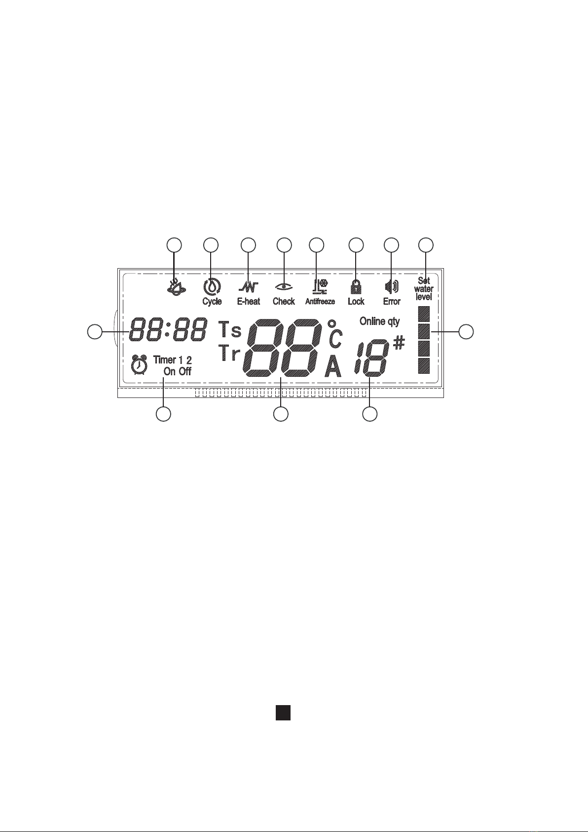
3. Outline of functions
3.1 Outline of functions
This wire controller provides the follow-
ing functions:
1) Connect with the heating water
system through the five terminals A,
B,P,Q and E.
2) Set the action mode through the
keypad operation.
3) Provide the LCD display function.
4) Provide the timing startup function.
5) Display the clock and timing startup
time signal.
3.2 Overview of power-off memory
function
Each power-off, the wire controller will
automatically record the ON/OFF state,
water temperature setting, circulating
water temperature setting and water level
setting informations before power-off;
when re-power on, the wire controller will
follow the above states and send relative
signals to the unit, make sure the unit can
be operated as the set states by the user.
But after re-power on, the clock will back
to the default value, the user has to re-
adjusted If the timer function has been
set before power-off, and the function will
be erased after re-power on, but the data
will be stayed.

4. Name and function description of LCD screen of
wired controller
RUN

Function instruction
LOCK
ERROR
SETTING
WATER
LEVEL
WATER
LEVEL
STATE
Table 4-1
No. Name
RUN
CIRCULATING
E-HEATING
CHECK
ANTI-COLD
Display when the environment temperatue is lower than 2
ć, and it will be canceled when the environment tempera-
ture is higher than 3ć
When the main unit has error and protection, it will display
the error code and protection code
When display the water level, can set the range between
2 to 4 positions
The 4 water level ranges are: 0, 50%, 75%, 100%; water
level display order: actual water level->setting water level,
can query through “Page up” and “Page down” key
Display the locking state of the wire controller
Display when press the “Check” key to query parameters
Display when the electric auxiliary heating is operated
Display when the main unit enter to circulating heating water
Display when the main unit enter to heating water

CLOCK
TIMER
PARAMETER
DISPLAY MAIN
INTERFACE
QTY. OF
ON-LINE
UNITS
Display the hour and minute, and will change as the
addition of time, the “ : ” is the second indicating icon;
display 24 hours. That displays timing setting.
a) Display water tank temperature T5 in the initial interface
b) Setting water temperature Ts: 40~60ć, default value is
56ć;
c) Circulating setting water temperature Tr, display the
circulating temperature, 30~48ć, default value is 45ć;
d) The temperature display range is T5->Ts->Tr, use the
“page up” and “page down” keys to the next page, and
at the same time display the timer setting
e) The display order of query is Outlet water
temperatureT1->Outdoor pipe temperatureT3->Outdoor
environment temperatureT4->Air exhausting tempera-
ture TP->Current of compressor A->Current of
compressor B->Electric expansion valve opening->Hot
water valve opening->Fault->Protection->Outlet water
temperature T1…
The total parallel connected unit numbers will be displayed
at the initial interface, when it is queried, will display the
address of the queried unit, and select different units with
different addresses through “increase” and “decrease”
keys.
Display the timer setting

7
5. Names of keys on the wired controller and the
keypad operation description
This figure is for reference only, the specific please prevail in kind.
MODE BUTTON
TIMER ON BUTTON
FOLLOW ME BUTTON
TIMER OFF BUTTON
ELECTRICAL
HEATER BUTTON
RESET BUTTON
ON / OFF BUTTON
ADJUST BUTTON ▲
ADJUST BUTTON ▼
SWING BUTTON
ECONOMY BUTTON
FAN SPEED BUTTON
LOCK BUTTON
TIMER
ON
TIMER
OFF
FOLLOW
ME
AUXIL
HEATER MODE
RESET LOCK
FAN SPEED
ECO
SWING TEMP
①
②
③
④
⑤
⑥
⑦
⑧
⑨
⑩
12
13
11

ŚWATER LEV.
This key is used to set the outdoor water
level. After pressing this key, you can use
the “Increase” and “Decrease” keys to
adjust the water level. The water level
range is: 50%, 75%, 100%, and the
default value is 100%.
śCONFIRM
Each press this key, means confirm and
finish the last operation.
ŜCLOCK
At each power-on,the clock is initialized to
00:00. Each press of this button, the “hh”
of the “hh:mm” will be flashed, and it can
be ad justed the hour through the
“Increase” and “Decrease”key; press this
button again, the “mm” of the “hh:mm” will
be flashed, and it can be ad justed the
minute through the “Increase” and
“Decrease”key. After adjustment, no any
operations for 7s or press the “OK” key,
then the wire controller will confirm the
clock setting, and exit the clock adjusting.
ŝTIMER
Timing function is timing for 24 hours,
there are two timing method: “Timer on”,
“Timer off”.
When the screen is activated and
unlocked press this key will enter to the
timer setting state,if there are no key
operations or press the “OK” key during
the setting period, then will exit the timer
setting.
a. Timer setting
This key function can set the start time
and finish time of the timer. All can set two
sets timing, that are timing 1 on/ off,
timing 2 on/off. Press this key, it will
display “Timing 1” setting time “ ”,
press this key again, then enter to “Timing
1 on ” setting, the front two of “ ”
(means hour) will be flashed, then can
adjust. Press this key again, he last two of
“ ” (means minute) will be flashed,
then can adjust. Press this key again then
it will display “Timing 1 off ” setting time ,
press this key again, the front two of “
” (means hour) will be flashed, then can
adjust. Press this key again, he last two of
“ ” (means minute) will be flashed,
then can adjust. Then press this key
again will confirm the “Timing 1” setting.
After set the “Timing 1”, it will enter to
“Timing 2” setting. Press this key, it will
display “Timing 2” setting time “ ”,
press this key again, then enter to “Timing

2 on ” setting, the front two of “ ”
(means hour) will be flashed, then can
adjust. Press this key again, he last two of
“ ” (means minute) will be flashed,
then can adjust. Press this key again then
it will display “Timing 2 off ” setting time ,
press this key again, the front two of “
” (means hour) will be flashed, then can
adjust. Press this key again, he last two of
“ ” (means minute) will be flashed,
then can adjust. Then press this key
again will confirm the “Timing 2” setting.
Press the timer key, the process will as
follow:
Normal display —>”Display Timing 1 on
time”—>”Adjust Timing 1 on time
--hour”—>”Adjust Timing 1 on time
--minute”—>”Display Timing 1 off
time”—>”Adjust Timing 1 off time
--hour”—>”Adjust Timing 1 off
time--minute”—>”Display Timing 2 on
time”—>”Adjust Timing 2 on
time--hour”—>”Adjust Timing 2 on time
--minute”—>”Display Timing 1 off
time”—>”Adjust Timing 2 off time
--hour”—>”Adjust Timing 2 off time
--minute”—>Normal display
Main unit on and
off time period
The start and finish
time of Timing 1
The start and finish
time of Timing 2

b. Timing query function
Query through the “Page up” and “Page
down” keys.
c. Each on and off time under two
timing conditions as follow:
(Note: If it is separate setting “On” and
“Off” at the same time point, then “Off” is
the priority.)
ŞCANCEL
Long press ‘CANCEL’ key for 3 seconds
can cancel all the timing hours, the
related timing display will be disappeared.
şCHECK
Press this key to query the status informa-
tion of any unit. Under default status,
press this key, the icon “ ” will show
up, and use the “Increase” and
“Decrease" keys to select the needed
query unit. After selecting to query
aspecific unit, use the “Page Up” and
“PageDown" keys to query the status
information of this unit. The query
sequence is:
Outlet water temperatureT1->Outdoor
pipe temperatureT3->Outdoor environ-
ment temperatureT4->Air exhausting
temperature TP->Current of compressor
A->Current of compressor B->Electric
expansion valve opening->Hot water
valve opening->Fault->Protection-
>Outlet water temperature T1ĊĊ
ŠRESET
Use a 1mm-diameter round stick to press
this button, and the current setting will be
cancelled and the wire controller enters
the reset status.
šON/OFF
In the power-off status, press this key
and the startup indicator comes on, and
the wired controller enters the startup
status and keeps the current set informa-
tion such as operation mode, temperature
value and timing. The information is
transmitted according to the code specifi-
cations. In the startup status, press this
key once, and the startup indicator goes
off and transmits the shutdown informa-
tion.
ŢWATER TEMP.
Press this key to enter the procedure of
setting water temperature signals. Use
the “Increase” and “Decrease" keys to set
it. The water temperature setting range is

40°C~55°C, and the default value for the
unit is 50°C .
CYC.TEMP.
This key is used to set the inlet tempera-
ture of the circulating heating water. After
pressing this key, you can use the
“Increase” and “Decrease” keys to adjust
the inlet temperature Tr of the circulating
heating water. The temperature range is
30~48°C, and the default temperature is
45°C.
LOCK
Use a 1mm-diameter round bar to press
this button to lock the current setting, and
the icon “LOCK” and “ ” will be
displayed. Press this button again to
unlock and the icon “LOCK” and “ ” will
be dissppeared..
6. Error alarm handling
When the unit fails or the wire controller
detects failure of communication with the
main equipment, the indicator blinks, and
the icon “ ” will be flashed. After all
errors of the system and the wire controller
are eliminated, the indicator stops blinking,
and the icon “ ” will be disappeared.
The fault indicator and the operation
indicator share the same LED.

3
3Ƚ3
3
3)
(
(
(
(
(
(
(
((
()
3
(
(
Table 6-1
Appendix: Fault code list
Error of the water temperature sensor inner the water tank
Communication error
Power supply wire phase error
Error of outlet water temperature
Error of the pipe of condenser temperature
Error of a outdoor ambient temperature
Error of a electric heater temperature
Error of detecting circulating water pressure
Communication error of function locking module and main board
System low pressure protection
System high pressure protection
System current protection
EEPROM error
Over high outlet water temperature protection
Water pressure detection error(Only main unit)
Function locking module is under locking state
Note: Some error codes are not listed, please query the main unit fault code list.

7. Technical indices and
requirements
EMC and EMI comply with the CE
certification requirements.

C./ Industria, 13 l Polígono Industrial El Pedregar
08160 Montmeló
Barcelona (Spain)
Phone: (0034) 93 390 42 20
Fax: (0034) 93 390 42 05
www.giatsu.com
Table of contents
Other Giatsu Remote Control manuals