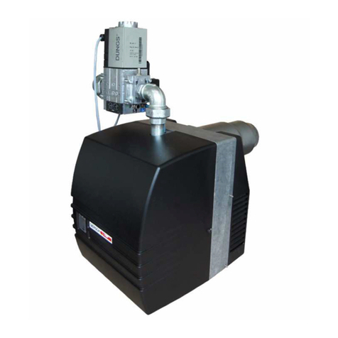
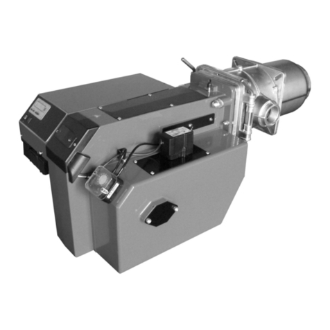
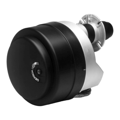
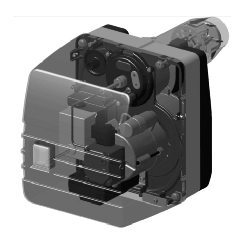
Giersch GL20-Z-L-LN Manual

Technical Information • Installation Instructions
Oil
Issued May 2011
Right reserved to effect techn. modifications
in the interest of product improvement!
GB
GL20-Z-L-LN

E.25.05.11
2
Contents
1. General information ............................................................................................................................3
2. Safety guidelines ................................................................................................................................3
3. Maintenance ....................................................................................................................................... 3
4. Declaration of conformity ....................................................................................................................3
5. Boiler connection dimensions .............................................................................................................4
6. Key for code designation ....................................................................................................................4
7. Technical specifications......................................................................................................................4
8. Installing flange and burner ................................................................................................................5
9. Connecting to power supply ...............................................................................................................6
10. Installing the oil line ............................................................................................................................7
11. Oil pump .............................................................................................................................................8
12. Checking the operation of the flame monitor control unit ...................................................................9
13. Setting the air flow rate.....................................................................................................................11
14. Actuator drive.................................................................................................................................... 12
15. Setting the ignition electrodes........................................................................................................... 12
16. Service position ................................................................................................................................13
17. Adjusting the inlet nozzle..................................................................................................................13
18. Notes about the mixing unit .............................................................................................................. 14
19. Nozzle replacement..........................................................................................................................14
20. Nozzle replacement..........................................................................................................................14
21. Start-up .............................................................................................................................................15
22. Calibration of the boiler-burner ......................................................................................................... 15
23. Flue connection ................................................................................................................................15
24. Exhaust gas thermometer................................................................................................................. 15
25. Circuit diagram ................................................................................................................................. 16
26. Troubleshooting ................................................................................................................................ 17
27. Adjustment table ...............................................................................................................................18
28. Explosion drawings / spare parts lists............................................................................................... 20
29. Dimensions.......................................................................................................................................26
30. Working ranges................................................................................................................................. 26

E.25.05.11
General information
3
1. General information
The GL20-LN oil burners are tested and approved to DIN EN 267 for heating oil EL according to
DIN 51603, ÖNORM C 1109, SN 181 160/2.
We recommend that the operator use low-sulphur heating oil EL or "eco heating oil" (where regionally available).
2. Safety guidelines
The rules of good engineering practice as well as construction supervision and statutory requirements must be
observed during installation and operation of the system.
Assembly, oil and flue gas connections, commissioning and connection to the power supply, as well as mainte-
nance and servicing may only be performed by a certified specialist.
Electrical connections must be in conformity with the applicable VDE, SEV and ÖVE specifications as well as
the regulations of the local utility.
Work on electrical equipment may only be carried out by qualified personnel in accordance with the relevant
VDE, SEV and ÖVE regulations.
Risk of injury by fan wheel on activation in service position.
3. Maintenance
The equipment must be checked regularly by trained personnel to ensure reliable and safe functioning of the
system. Annual maintenance is required. We recommend that users take out a maintenance contract with a
certified specialist.
4. Declaration of conformity
We declare that GL20-LN Series oil blower burners with the assigned product identification number
meet the basic requirements of the following directives:
• "Electromagnetic Compatibility" according to Directive 2004/108/EEC
• "Machinery Directive" as per directive 2006/42/EG in conjunction with DIN EN 60204-1
• "Efficiency Directive" according to Directive 2006/42/EWG in conjunction with EN 267/Ed.10.91
These products conform with the design sample tested at the designated centre 0032.

E.25.05.11
4
Boiler connection dimensions (All dimensions are given in mm)
5. Boiler connection dimensions
(All dimensions are given in mm)
6. Key for code designation
7. Technical specifications
Burner type
Technical specifications GL20/1-LN GL20/2-LN GL20/3-LN
Burner capacity
in kW
in kg/h
44 - 116
37 - 9.8
78 - 216
66 - 18.2
126 - 262
106 - 22.1
Mode of operation 2-stage
Voltage 1 / N / PE ~ 50 Hz / 220 - 240 V
Max. power consumption at start / during
operation
4 A max. / 2 A eff. 6.5 A max. / 3.5 A eff.
Electric motor power (at 2800rpm) in kW 0.250 0.370 0.370
Oil pump (type) Suntec AT2 45 D
Flame failure controller Flame failure controller IRD 1010
Control box DKO 972 Mod. 22
Weight in kg 16.5 20 23.5
M8
k
d
f
90°
GL20/1 GL20/2/3
Hole diameter d1 102 130
Hole circle diameter k 140-180 170-200
Outer diameter f 194 220
d1
GL20/1-Z-L-LN
LowNox"
Luftabschlussklappe
Zweistufig
Baugröße
Baureihe
burner series
burner type
2 stage
air damper
LowNox

E.25.05.11
Installing flange and burner
5
8. Installing flange and burner
GL20/1/2-LN
• Attach the sliding flange and gasket loosely to the
door of the boiler.
• Slide in the burner.
• Observe the tightening sequence for the screws.
• Raise the burner when tightening the screws.
GL20/3-LN
• Attach the sliding flange and gasket loosely to the
door of the boiler.
• Remove the front part of the burner pipe from the
burner, slide in the burner.
• Observe the tightening sequence for the screws.
• Raise the burner when tightening the screws.
• Replace the front of the burner pipe and
fasten it (see figure).

E.25.05.11
6
Connecting to power supply
9. Connecting to power supply
• Disconnect the system from the power supply. Main switch "OFF".
• Check the polarity of all connectors.
• Connect the plug unit as indicated in the connection diagram. Route the flexible control lines so that the
hinged door of the boiler is not obstructed.
• Connect the 4-pin connector for capacity regulation (X31) to the black-green socket unit on the burner
(X32).
• Where the X11 and X31 connections are used, check for correct assignment according to the connection
diagram.
• Connect the 7-pin connector of the boiler control (X11) to the black-green socket unit at the burner
(X12)..
• The connection cable to the 7-pin X11 connection on the plug unit must be fused with max. 6.3 A slow-
acting or max. 10 A fast-acting.
Connection diagram:
B4
S3
T2
T1
N
PE
L1
N
PE
L1
N
N
F1 F3
F21
H11
P11
H13
Q1 X11 X12
Buchsenteil X32,X12
am Brenner
Steckerteil X31,X11
zum Kessel
T8
T7
T6
B5
Buchsenteil X32, X12
am Brenner
Steckerteil X31,X11
zum Kessel
X32
N
F22
P12
X31
Anschluss für GL20-Z-L
H12
Connection for GL20-Z-L
connector unit X31, X11
boiler control
socket unit X31, X12
on burner
connector unit X31, X11
boiler control socket unit X31, X12
on burner
Key:
F1 External fuse
F21, F22 External temperature controller 1st/2nd stage
F3 External safety temperature limiter
Q1 Heater power switch
H11, H12 Ext. status lamp
H13 Ext. fault indication lamp
L1 Phase
PE Grounded conductor
P11, P12 Operating hours counter
Y9 Ext. control
N Neutral conductor

E.25.05.11
Installing the oil line
7
10. Installing the oil line
Twin-pipe system
Single-line system
The tables refer to heating oil EL 4.8 cSt and the inner diameter (Di) of the oil pipes. 4 brackets, 1 valve and
1 non-return valve were included for resistance with the suction line length. To prevent possible oil vapours, the
dimension X should not exceed a length of 4 m.
• Connect oil pump to the oil line with the enclosed metal hoses.
• The pump should be connected with a feed and return line (twin-pipe system).
• With elevated tanks, the pump can be converted to a single-pipe system.
For pure single-pipe operation the bypass stopper must be unscrewed out of the return line opening
(see page 8) and the return line opening must be sealed with a gasket and metal stopper.
Pump Di
[mm] H [m]
4 3 2 1 0 -1 -2 -3 -4
Suntec 621 18 16 13 11 8 5 - -
867 58 50 42 34 25 17 9 -
10 100 100 100 100 82 62 42 21 -
Oil
throughput
[kg/h]
Di
[mm]
H [m]
4 3 2 1 0 -1 -2 -3 -4
up to 2.5
477 68 58 49 40 31 22 13 -
6100 100 100 100 100 100 87 64 18
8100 100 100 100 100 100 100 100 56
2.5 - 5.0
439 34 29 25 20 16 11 6 -
6100 100 100 100 100 79 56 32 9
8100 100 100 100 100 100 100 65 28
5.0 - 10.0
419 17 15 12 10 8 - - -
698 86 74 63 51 39 28 16 4
8100 100 100 100 100 100 88 51 14
10.0 - 23.0 642 37 32 27 22 17 12 7 -
8100 100 100 85 69 54 38 22 6

E.25.05.11
8
Oil pump
We recommend that you use a heating oil filter with return inlet when changing over to a single-pipe system.
This leaves the pump operating in twin-pipe mode. Install the feed
and return burner hoses to the filter. Open the oil tap on the filter.
Start up the system.
11. Oil pump
The pump pressure must be set to match the relevant capacity.
The specified pump pressures are standard values and may vary according to system conditions.
For this:
Remove the 4 sealing plug.
Screw in the pressure gauge and adjust the pump pressure with the regulating screw.
1 = Feed line
2 = Return line
3 = Pressure pipe connection
4 = Pressure measuring connection
5 = Vacuum measuring connection
6 = Pressure adjustment 1st stage
7 = Pressure adjustment 2nd stage
8 = Solenoid valve 1st stage
9 = Solenoid valve 2nd stage
9
6
5
7
1
2
3
4
8
4

E.25.05.11
Checking the operation of the flame monitor control unit
9
12. Checking the operation of the flame monitor control unit
The DKO control unit uses a microprocessor-based programming sequence to produce extremely stable tim-
ings independent of fluctuations in the line voltage and ambient temperature. The built-in visual information sys-
tem allows continuous progress monitoring and provides information on the causes of a fault shutdown.
The last cause of fault is stored in the appliance and can even be reconstructed when restarting the appliance
after a power failure. The control unit is protected against under voltage. A restart takes place in all cases fol-
lowing a mains power failure.
Information system
The information system displays information on the processes in connection with burner control and monitoring.
In addition to monitoring the program, it allows faults to be localised immediately during the program sequence
or operation without the need for auxiliary devices.
The troubleshooting button has an LED. The LED is used to indicate status information and faults. The status
messages are intended for output to Satro Com and Satro Pen, and cannot be interpreted by operators due to
the rapid flashing sequence. Status messages are translated to plain text by the Satro Com and Satro Pen
devices. Faults are transferred at a slower flashing speed and can therefore be interpreted by users.
Program sequence DKO 972 Mod.22
The built-in microprocessor controls both program sequence and the information system. The individual phases
of the program sequence are indicated as flash codes.
Fault cause diagnosis
In the event of a fault, the LED remains continuously lit. Every 10 seconds, this is interrupted by the flashing code
indicating the fault that has occurred. This results in the following sequence repeats itself continually until the
fault is acknowledged, i.e. the appliance is reset.
Sequence:
Message Flashing Code
Wait until the release thermostats are closed
Pre-ignition phase
Safety and post-ignition times
Operation
Mains undervoltage
Waiting for RT or pcb fuse defective
Failure message Flashing Code Cause of fault
Fault shutdown No flame detection within the safety interval
Extraneous light
fault
External light during monitored phase, sensor possibly defective
Thermostat time-out FT contact does not close within 400 sec.
LED continuously ON Dark phase
lasting 10 secs. lasts 0.6 secs.
Dark phase
lasting 1.2 secs.
Flashing Code
.
.
.
.
.
= short pulse
= long pulse
= short interval
= long interval
Description:

E.25.05.11
10
Checking the operation of the flame monitor control unit
Function test
A safety inspection must be carried out on the flame monitor on commissioning as well as after a service or
lengthy shutdown.
Start-up with covered flame detector:
The burner must go into fault mode after the safety period.
Start-up with flame detector exposed to light:
The control device must switch over to fault mode, see IRD function description.
Normal start-up if the burner is in operation, cover the flame detector:
Attempted restart; upon expiry of the safety period, the control device must switch
over to fault mode.
Safety and switching functions
If a flame failure occurs during operation, the fuel feed shuts off immediately and the system tries a restart, with
pre-aeration and retarded ignition. If no flame results, the control box indicates a fault after the safety period
expires. The control unit also goes into lockout mode if external light is present during the pre-aeration interval.
The device remains locked out and the cause of the fault is indicated until the automatic burner control system
is unlocked (enabled) by internal or external fault clearing.
The control unit may only be connected or disconnected when the master switch is at "OFF", or the 7-pin
connector is disconnected. Incidence of external light on the flicker detector (e.g. due to a sight glass)
must be prevented. Only then is a fault-free functioning of the system guaranteed. The flicker detector
must be set so that the incidence of light (e.g. through a sight glass or after-glowing refractory bricks)
does not affect the flicker detector.
Satronic: DKO 972 Mod. 22
t
v1
= pre-purge and pre-ignition time 17 sec.
t
v2
= delay time, 2nd stage 60 sec.
t
f
= flame simulation supervision 5 sec.
t
s
= safety period 5 sec.
t
n
= post-ignition time 20 sec.
Post-ventilation after
flame cut-off -
Delay after switching-off fault -
Flicker detector IRD 1010

E.25.05.11
Setting the air flow rate
11
Function test IRD
Carry out the following checks after commissioning and each
time after the burner has been serviced:
1. Set the maximum sensitivity at the flicker detector and
start the burner:
After the start pulse, no LED may light up during
pre-ventilation.
2. During operation, pull out the sensor and
cover it:
Both LEDs must extinguish. The control unit attempts
to restart and switch to fault on expiry of the safety
interval.
3. Restart with sensor covered:
No display may appear. The control unit must go into lockout mode on expiry of the safety interval.
4. Burner start-up with externally illuminated sensor: In the case of external lighting using a fluorescent lamp,
the control device must switch over to fault mode within approx. 22 seconds. Daylight, lighter or incandescent
lamp are not suitable for simulation.
5. During normal burner operation, turn the potentiometer back carefully from max. setting until LED 1 flickers.
Then increase the potentiometer setting until both LEDs come on. If LED 1 does not flicker at or before min.
position 1: leave the potentiometer at position 1-2.
IMPORTANT !
Burner in operation = both LEDs on
Burner in pre-ventilation = both LEDs off
Set the LED display so that both LEDs clearly light up both in cold and warm burner states after the ignition has
been switched off.
13. Setting the air flow rate
To set dimension "A", loosen the locking nut. Use the adjusting
screw to modify the air flow rate to match the capacity in accord-
ance with adjustment table dimension "A". The values in the
adjustment table correspond to the free thread length (see figure).
If there is overpressure in the combustion chamber, set the value
higher; if there is underpressure, the value must be reduced.
Readjustment is necessary in any case on account of the type of
plant.
To achieve uniform burning values, we recommend installation of a
draught limiter or auxiliary air unit.
Smaller value:
turn counter-clockwise = Less air, more CO
2
Higher value:
turn clockwise = More air, less CO
2
A
-+

E.25.05.11
12
Positioning drive STA...
14. Positioning drive STA...
The positioning drive adjusts the air valve position or trips the
solenoid valve on two-stage burners
with air shutoff. Make the adjustment using the limit switch cams
on the positioning drive roller.
The cam positions for adjusting the burner to the required boiler
capacity can be taken from the adjustment.
For this:
Remove the cover from the positioning drive. Alter the cam posi-
tions via the adjusting screws with a standard screwdriver.The
switch cams can be adjusted when calibrating the burner.
Higher setting = More air, pressure increases
Lower setting = Less air, pressure decreases
Please note the following when adjusting the switch cams:
- Do not set cam position ST1 via ST 2.
- Set cam position MV2 roughly 5° to 10° above cam position ST1.
- Check cam position MV2 after correcting cam position ST1.
- After adjustment of ST1 and ST2, it is necessary to over to the next stage so that the adjustment
becomes effective.
- After adjusting the burner, refasten the cover on the positioning motor and set the switch (see also page 15)
of the 2nd-stage control unit to the position to 2nd stage.
15. Setting the ignition electrodes
Press the ignition electrodes together lightly as shown in the schematic until the specified dimension is
reached. The specified dimensions are for checking purposes.
GL20/1-LN GL20/2/3-LN

E.25.05.11
Service position
13
16. Service position
Risk of injury by fan wheel on activation in service position.
- Release quick-release locks (5 x) and detach base plate,
- Position the keyhole orifices in the base plate onto the cylinder
head screws of the housing and snap into place.
Caution !
Ensure the base plate is correctly seated in the housing.
17. Adjusting the inlet nozzle
The position of the inlet nozzle is preset at the factory, but can be
adapted to different system operating conditions, altitude above
sea level and outputs.
To adjust, loosen the screws (see figure). Use the scale and mark-
ing to set the new selected position (see adjustment table for scale
values).
Refasten the inlet nozzles in their new position.
Position of inlet nozzles:
- = Low blower output (-40°)
+ = Maximum blower output (16°)
Scale
Marking
-+

E.25.05.11
14
Notes relating to the mixing unit
18. Notes relating to the mixing unit
To disassemble the mixing unit, loosen the Allen screw, size 4.
During subsequent assembly, it is essential to ensure the correct position of the mixing head. In the GL20/1-LN
version, the ignition electrodes are on the lower part of the unit.
GL20/1-LN GL20/2/3-LN
19. Nozzle replacement
- Bring the base plate into position,
- Remove the ignition cable from the ignition electrode,
- Use a size 4 Allen key to release the mixing head,
- Retract the mixing head upwards,
- Remove the oil nozzle (SW16 spanner) while securing the
nozzle stem with an SW 19 spanner to prevent rotation,
(Fig.)
- Replace the oil nozzle,
- Reinstall the mixing head (ignition electrode facing down),
- Attach the ignition cable.
20.Fitting the recirculation tube
Fit the recirculation tube flush with the burner tube edge
(as shown).

E.25.05.11
Start-up
15
21. Start-up
For burner commissioning, the first stage can be set manually
using the switch on the socket unit.
The switch on the socket unit must be at the position 2nd stage
during operation. The air throttle is closed in standstill. In stage 1,
ignition and pre-ventilation (approx. 15 secs.) is activated after
the air throttle opens. Then the solenoid valve opens and
releases the oil for stage 1. After flame formation and completion
of the ignition phase, the burner switches over to the 2nd stage
after 60 secs. Then, set the required pump pressure in accord-
ance with the nozzle selection table (see adjustment table). Fol-
lowing a brief period of operation in stage 2, measurements
(CO
2
, soot accumulation and exhaust air temperature) can be
performed. If necessary, the air can be readjusted with the adjust-
ing screw and/or positioning motor ST2.
Important:
Set dimension "A" only in the 2nd stage!
In order to check the burning in the 1st stage, set the switch on the socket unit to
1st stage. Set the air flow at cam ST1 of the positioning motor.
After calibration of the burner, refasten the hood of the positioning motor. Switch over the switch on
the connector to position 2nd stage. On completion of work, set the control thermostat 2nd stage lower than
the control thermostat 1st stage!
22. Calibration of the boiler-burner
A precise calibration is necessary for a burning that is low in emissions and energy saving. For this purpose, a
burner is assigned to the boiler in accordance with the work ranges and taking into account the combustion
chamber resistance. The immersion depth of the burner pipe to the respective burner chamber is set via the slid-
ing flange.
23. Flue connection
The prerequisite for a faultless functioning of the firing system is a correctly dimensioned flue. Dimensioning is
effected in accordance with DIN EN 13384, Part 1 in consideration of DIN 18160 and the local regulations and
based on the boiler and burner outputs.
Refer to the technical information and installation instructions of the heat generator for further information.
24. Exhaust gas thermometer
For exhaust gas temperature monitoring the heating system should be equipped with an exhaust gas thermom-
eter. The higher the exhaust gas temperature, the greater the exhaust gas loss. Rising exhaust gas tempera-
tures indicate increasing deposits that will reduce the degree of combustion efficiency.
In the event of an increasing exhaust gas temperature, have the heating system cleaned and readjusted by a
specialist.

E.25.05.11
16
Circuit diagram
25.Circuit diagram
SP_1-381.1
GA or
Ext. valve
Boiler control
B6 Flame detector IRD 1010
F11 Ext. fuse, boiler control
6.3 AT / max. 10 AF
F21 Ext. temperature control
F22 Ext. temperature control, 2nd stage
F3 Safety temperature limiter
H11 External fuse
H12 Ext. status lamp, 2nd stage
H13 Ext. fault indication lamp
M1 Burner motor, 250 W
P11 Ext. operating hours counter
P12 Ext. operating hours counter, 2nd stage
P21 Operating hours counter (option)
Q1 Heater power switch
S1 Control unit DKO 972
S3 Switch, 1st / 2nd stage
S9 OC / Oil Control (option)
SK1 Strap terminal S1
SK2 Strap terminal S2
T3 Ignition transformer
X11 Boiler control plug unit, 7-pin
X12 Burner socket unit, 7-pin
X31 Boiler control plug unit, 4-pin
X32 Burner socket unit, 4-pin
X82, X83 single-pole terminal strip
X111 Plug unit, ext. solenoid valve
Y4 Actuator drive
Y6 Oil solenoid valve
Y7 Oil solenoid valve, 2nd stage
PE Grounded conductor
Colour code:
bl = bue
br = brown
ge = yellow
gr = gray
grü = green
rt = red
sw = black
vio = violet
ws = white

E.25.05.11
Troubleshooting
17
26. Troubleshooting
Observation Cause Remedy
Burner motor is not run-
ning
Fuse faulty
Safety thermostat locked
Controller set temperature exceeded
Control box faulty
Motor faulty
Replace
Unlock
Renewed start attempt after temperature drop
Replace
Replace
Burner starts up (does
not start up) and on
expiry of the safety inter-
val switches to fault
a) With flame formation:
Flame detector soiled, defective, not
inserted properly or not set correctly
Air sleeve not positioned correctly
Control box faulty
Recirculation volume to high
b) Without flame formation:
No ignition
No oil feed:
Valves, oil line closed
Oil tank empty
Filter dirty
Leak in oil line
Pump defective
Leak in check valve
Nozzle dirty or faulty
Solenoid valve faulty
External light
Motor–pump coupling faulty
Clean, replace, connect correctly or adjust sen-
sitivity
Correct position
Replace
Reduce recirculation volume
Check the ignition electrode and setting,
ignition transformer and cable
Open
Top up oil
Clean
Seal
Replace
Seal
Replace nozzle
Replace
see "Checking the operation of the flame moni-
tor control unit"
Replace
Flame extinguished dur-
ing operation
No oil
Nozzle filter blocked
Oil filter or oil feed lines dirty
Entrapped air
Solenoid valve faulty
Add oil
Replace nozzle
Clean filter and line
Check suction line and fittings
Replace
Mixing unit is heavily
fouled by oil or is heavily
coked
Incorrect setting
Wrong nozzle size
Combustion air flow rate is incorrect
Boiler room is not sufficiently ventilated
Correct the setting dimensions
Replace
Readjust burner
Make sure that the ventilation orifices are large
enough

E.25.05.11
18
Adjustment tables
27. Adjustment tables
The values given in the tables are only setting values for start-up.
A correction is required in any case (due to the system design).
The specified oil throughput values in the nozzle selection tables refer to a viscosity of approx.1.8 cSt for pre-heated heating oil.
and approx. 4.8 cSt for heating oil at 20° C.
Dimension “A“ refers to an altitude of 300 m above NN, and an ambient temperature of approx.20° C and a practically-oriented
combustion chamber pressure for an exhaust gas CO
2
-content of around 12.5%.
We recommend Danfoss 60°H nozzles for GL20/1-Z-L-L N.
Burner
capacity
Boiler
capacity
at
ηk = 93%
Oil nozzle
Danfoss
Oil pump pres-
sure
Oil throughput Rough air
setting
Dimension
“A”
Positioning motor Air pressure
upstream of
retarding disc
Pos.
inlet noz-
zle
ST2 ST1 ST2 ST1 ST2 ST1 ST0 ST2 MV2 ST1 ST2 ST1
[kW] [kW] [kW] [gph] [bar] [bar] [kg/h] [kg/h] [mm] [ ° ] [ ° ] [ ° ] [ ° ] [mbar] [mbar] [ ° ]
GL20/1-Z-L-LN
60 44 56.0 0.85/60°H 21 11 5.0 3.7 20.5 0 48 15 10 8 5 -40
65 40 60.0 1.00/60°H 20 11 5.5 3.4 21.5 0 50 15 12 8 5 -20
70 50 65.0 1.10/60°H 20 11 5.9 4.2 22.0 0 55 20 15 8.5 5.2 -20
80 55 74.5 1.25/60°H 20 10 6.7 4.6 24.0 0 60 25 20 8.5 5.5 0
85 60 79.0 1.35/60°H 20 10 7.2 5.1 25.0 0 62 25 23 8.8 5.8 0
95 66 88.3 1.50/60°H 20 10 8.0 5.6 25.5 0 65 28 25 8.8 5.8 0
100 72 93.0 165/60°H 20 10 8.4 6.1 26.0 0 70 35 30 9.0 5.8 0
110 78 102.0 175/60°H 20 10 9.3 66 27.0 0 80 37 33 9.0 6.0 0
116 78 108.0 175/60°H 21 10 9.8 66 27.5 0 85 37 35 9.0 6.0 0

E.25.05.11
Adjustment tables
19
We recommend Danfoss 60°H nozzles for GL20/2-Z-L-L N.
We recommend Danfoss 60°H and Delavan 60°A nozzle s for GL20/3-Z-L-LN.
Burner
output
Boiler
output
at
η93
Oil nozzle
Danfoss
Oil pump pres-
sure
Oil throughput Rough air
setting
Dimension
“A”
Positioning motor Air pressure
upstream of the
retarding disc
Pos.
inlet noz-
zle
ST2 ST1 ST2 ST1 ST2 ST1 ST0 ST2 MV2 ST1 ST2 ST1
[kW] [kW] [kW] [gph] [bar] [bar] [kg/h] [kg/h] [mm] [ ° ] [ ° ] [ ° ] [ ° ] [mbar] [mbar] [ ° ]
GL20/2-Z-L-LN
111 85 103 175/60°H 20 12.0 9.4 7.1 31.7 0 33 25 18 66 4.2 -5
125 88 116 2.00/60°H 20 10.5 10.5 7.4 32.4 0 36 20 15 7.0 3.9 0
140 98 130 2.25/60°H 20 10.0 11.8 8.2 34.2 0 40 20 15 8.3 4.3 16
156 108 145 2.50/60°H 20 10.0 13.1 9.1 396 0 45 25 20 8.8 4.5 16
185 127 172 275/60°H 22 10.5 156 107 41.1 0 60 35 30 116 5.4 16
204 141 190 3.00/60°H 22 10.5 17.2 11.9 43.5 0 80 40 33 12.2 5.6 16
GL20/3-Z-L-LN
180 125 167 275/60°H 21 10 15.2 10.5 41.0 0 55 40 28 12 6 16
200 138 186 3.00/60°H 21 10 16.9 116 42.0 0 60 40 32 12 6 16
222 157 206 3.50/60°A21 10 187 13.2 44.5 0 76 40 50 11.5 5.7 16
260 182 242 4.00/60°A21 10 21.9 15.3 53.0 0 100 55 42 9.5 3.8 16

E.25.05.11
20
Explosion drawings / spare parts lists
28.Explosion drawings / spare parts lists
GL20/1-LN
ZBZ_1-517
Table of contents
Other Giersch Burner manuals
Popular Burner manuals by other brands

Bentone
Bentone B 55-3R Installation and maintenance instruction

EcoSmart Fire
EcoSmart Fire ESF.1.B.G28 Installation, operation and maintenance manual

Riello Burners
Riello Burners RG2 Installation, use and maintenance instructions

NetZero
NetZero NetZero FLA Series installation manual

Cuenod
Cuenod NC14 GX107/8A manual

Planika
Planika KL21 Square Installation and user manual