ISTRUZIONI DI MONTAGGIO - FITTING INSTRUCTION - INSTRUCTIONS POUR LE MONTAGE -
INSTRUCCIONES DE MONTAJE - MONTAGEANLEITUNG - PROVENCE
5
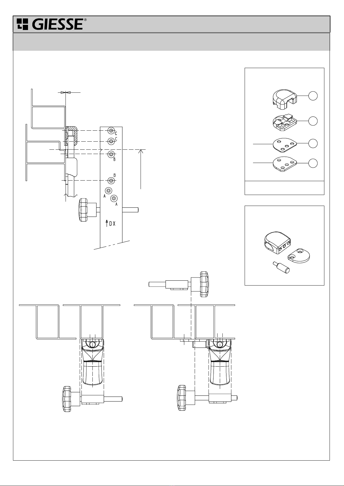
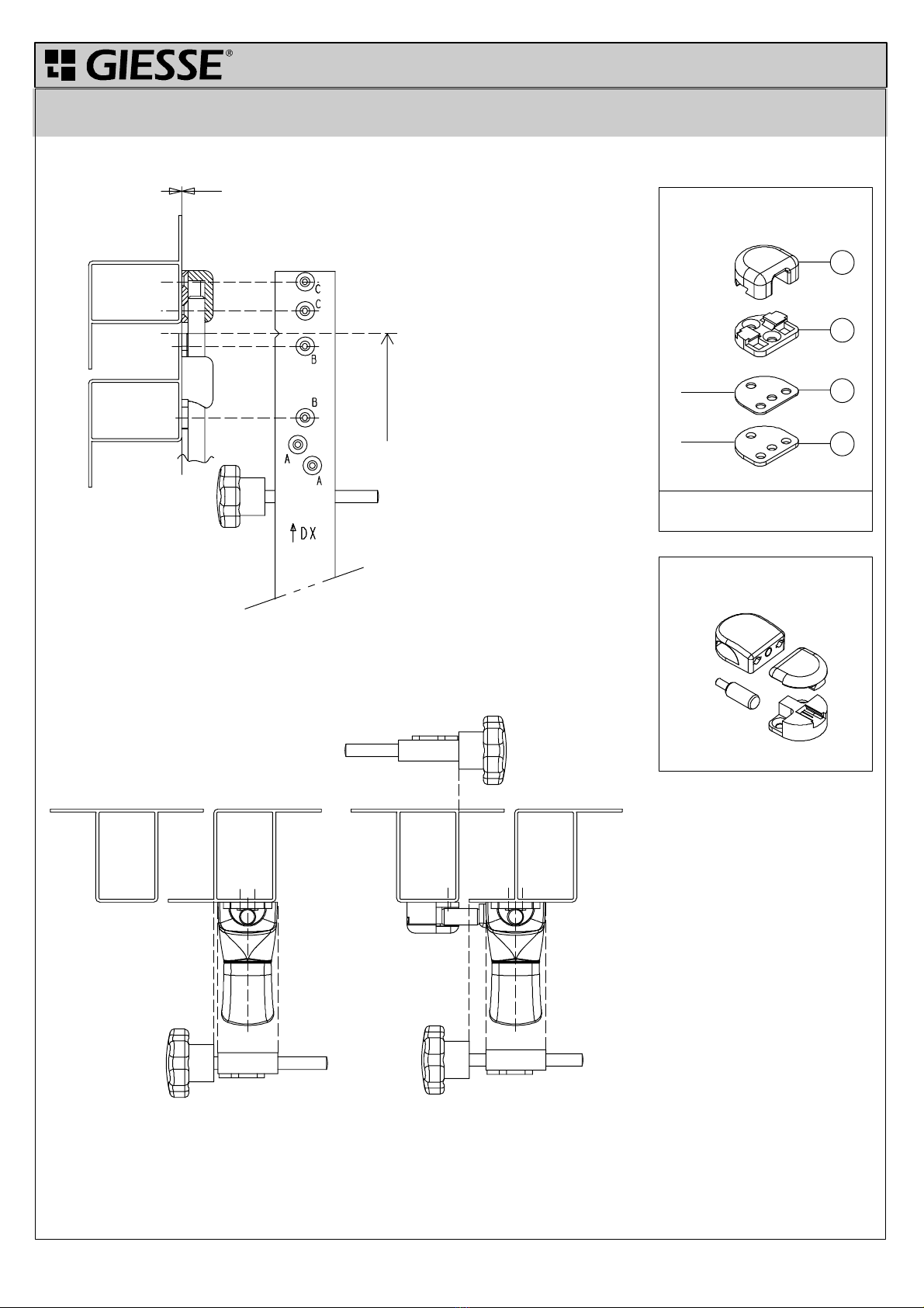
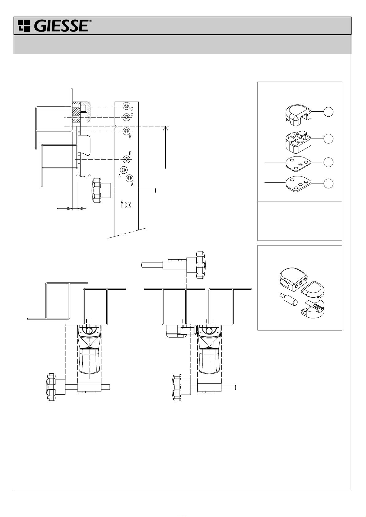
2. LAVORAZIONI
Stabilire l'altezza della cremonese (Hc) ed eseguire le
lavorazioni di foratura dell'anta ed eventualmente del te
laio utilizzando la dima art. 03280 (Fig. 2A - 2B - 2C). Per
il corretto posizionamento della dima fare riferimento an
che ai disegni dei nodi delle differenti tipologie di apertura
(Fig. 3 - 4 - 5 - 6 - 7).
ISTRUZIONI DI IMPIEGO DIMA
↑DX: identifica "l'alto" , e quindi come orientare la dima,
per eseguire le lavorazioni sul montate di un'anta con
apertura destra.
↑SX: identifica "l'alto" , e quindi come orientare la dima,
per eseguire le lavorazioni sul montate di un'anta con
apertura sinistra (dall'orientamento DX ruotare la dima di
180°).
1: indice che identifica il centro della cremonese ( quota
Hc Fig. 2C) e dell'incontro terza chiusura per il posiziona
mento in altezza sull'anta.
2: indice che identifica il posizionamento della dima in
riferimento all'anta per eseguire le forature del "guida aste"
e degli "incontri" per "apertura interna complanare e sor
monto ed esterna complanare".
3: riferimento per la foratura del "guida aste" nell'appli
cazione "apertura esterna sormonto".
4: viti di registro per il posizionamento trasversale della
dima sul montante dell'anta.
A: fori da utilizzare per eseguire la lavorazione per la
cremonese (utilizzare punta ∅2.7).
B: fori da utilizzare per eseguire la lavorazione per i gui
da asta (utilizzare punta ∅2.7).
C: fori da utilizzare per eseguire la lavorazione per gli
incontri (utilizzare punta ∅2.7).
D: fori da utilizzare per eseguire la lavorazione per gli
incontri 3a chiusura (utilizzare punta ∅2.7).
2. MACHINING
Set the height of the Cremone bolt (Hc). Drill the
window and the frame (where necessary) using the
template art. 03280 (Figs. 2A - 2B - 2C). For the cor
rect position of the template, refer to the node dra
wings for the various opening types (Figs. 3 - 4 -5 -
6 - 7).
TEMPLATE INSTRUCTIONS
↑DX: is the "top" to be used when drilling the
uprights of a window with right-hand opening.
↑SX: is the "top" to be used when drilling the
uprights of a window with left-hand opening; (if the
template is in the DX position, turn it through 180).
1: reference marking the centre of the Cremone
bolt (dimension Hc in Fig. 2C) and of the third lock ke
ep for height positioning on the frame.
2: reference on the template for drilling for the "rod
guide" and the "keep" holes for "internal flush and over
lapping opening" and "external flush opening" applica
tions.
3: reference for drilling the "rod guide" holes on
"overlapping external opening" applications.
4: adjuster screws for positioning the template
crossways on the window upright.
A: holes for Cremone drilling
(use a ∅2.7 bit) .
B: holes for rod guide drilling
(use a ∅2.7 bit) .
C: holes for drilling keep holes
(use a ∅2.7 bit).
D: holes for third lock keep holes
(use a ∅2.7 bit).
2. PERCAGES
Définir la hauteur de la crémone (Hc), puis effectuer les
perçages du vantail et, le cas échéant, du châssis à l'aide du
gabarit art. 03280 (Fig. 2A - 2B - 2C). Pour positionner correc
tement le gabarit, il est important de consulter les dessins des
sections relatives aux différents types d'ouverture (Fig. 3 - 4 -5
- 6 - 7).
UTILISATION DU GABARIT
↑DX : indique le "haut", c'est-à-dire comment orienter le
gabarit pour effectuer les perçages sur le montant d'un vantail
avec ouverture à droite.
↑SX : indique le "haut", c'est-à-dire comment orienter le ga
barit pour effectuer les perçages sur le montant d'un vantail
avec ouverture à gauche (tourner le gabarit de 180par rapport
à l'orientation DX).
1 : indice indiquant le centre de la crémone (cote Hc Fig. 2C)
et la gâche du troisième point de fermeture pour le positionne
ment en hauteur sur le vantail.
2 : indice indiquant le positionnement du gabarit par rapport
au vantail pour effectuer les perçages du "guide-tringles" et des
"gâches" en cas d'ouverture vers l'intérieur avec fermeture à la
française et à recouvrement et en cas d'ouverture vers
l'extérieur avec fermeture à la française.
3 : repère pour le perçage du "guide-tringles" dans l'applica
tion "ouverture vers l'extérieur - fermeture à recouvrement".
4 : vis de réglage pour le positionnement transversal du ga
barit sur le montant du vantail.
A : trous à utiliser pour effectuer les perçages sur la crémone
(utiliser une mèche ∅2,7) .
B : trous à utiliser pour effectuer les perçages sur les guide-
tringles (utiliser une mèche ∅2,7) .
C : trous à utiliser pour effectuer les perçages sur les gâches
(utiliser une mèche ∅2,7) .
D : trous à utiliser pour effectuer les perçages sur les gâches
du troisième point de fermeture (utiliser une mèche ∅2,7).
2. BOHRUNGEN
Die Höhe des Getriebegriffs (Hc) festlegen und die Bo
hrungen am Flügel und ggf. am Rahmen mit Hilfe der
Bohrlehre Art. 03280 (Abb. 2A - 2B - 2C) ausführen. Zur
korrekten Anordnung der Bohrlehre siehe auch die Zeich
nungen der Querschnitte für die verschiedenen Öffnung
sarten (Abb. 3 - 4 -5 - 6 - 7).
ANWEISUNGEN FÜR DEN GEBRAUCH DER
BOHRLEHRE
↑DX: steht für "oben" und bezeichnet daher die Aus
richtung der Bohrlehre zum Bohren auf dem Senkrechtteil
eines rechts öffnenden Flügels.
↑SX: steht für "oben" und bezeichnet daher die Aus
richtung der Bohrlehre zum Bohren auf dem Senkrechtteil
eines links öffnenden Flügels (hinsichtlich der Markierung
DX die Bohrlehre um 180drehen).
1: Kennzeichnung des Mittelpunkts des Getriebegriffs
(Maß Hc Abb. 2C) und des Schließblechs für dritte
Schließstelle zur Höhenanordnung auf dem Flügel.
2: Kennzeichnung zur Anordnung der Bohrlehre im
Verhältnis zum Flügel für die Bohrungen der "Stan
genführung" und der "Schließbleche" für "nach innen
öffnende flächenbündige und flächenversetzte Fenster
und nach außen öffnende flächenbündige Fenster ".
3: Kennzeichnung für die Bohrungen der "Stan
genführung" bei der Anwendung "nach außen öffnende
flächenversetzte Fenster".
4: Einstellschrauben zur Queranordnung der Bohrlehre
auf dem Senkrechtteil des Flügels.
A: Löcher für die Bohrungen für den Getriebegriff (Bo
hrer- ∅2,7 verwenden)
B: Löcher für die Bohrungen für die Stangenführungen
(Bohrer- ∅2,7 verwenden)
C: Löcher für die Bohrungen für die Schließbleche (Bo
hrer- ∅2,7 verwenden)
D: Löcher für die Bohrungen für die Schließbleche 3.
Schließstelle (Bohrer- ∅2,7 verwenden)
2. PREPARACIONES
Establecer la altura de la cremona (Hc) y realizar los
trabajos de taladrado de la hoja y si es necesario del basti
dor utilizando la plantilla art. 03280 (Fig.) 2A - 2B - 2C).
Para el posicionamiento correcto de la plantilla, hágase
también referencia a los dibujos de los nudos de los dife
rentes tipos de apertura (Fig. 3 - 4 -5 - 6 - 7).
INSTRUCCIONES DE EMPLEO DE LA
PLANTILLA
↑Dcha: identifica el alto", y por lo tanto como orientar
la plantilla, para realizar los trabajos en el montante de
una hoja con apertura derecha.
↑Izqda: identifica el alto", y por lo tanto como orientar
la plantilla, para realizar los trabajos en el montante de
una hoja con apertura izquierda (desde la orientación
DCHA girar la plantilla 180).
1: Indicador que identifica el centro de la cremona (cota
Hc Fig. 2C) y de la platina de contacto tercer cierre para
el posicionamiento en altura en la hoja.
2: Indicador que identifica el posicionamiento de la
plantilla con referencia a la hoja, para realizar los taladra
dos de los guía varillas" y de las platinas de contacto" pa
ra "apertura interna coplanar y sobreposición y externa co
planar".
3: referencia para el taladrado de la guía varillas" en la
aplicación apertura externa sobreposición".
4: tornillos de ajuste para el posicionamiento transver
sal de la plantilla sobre el montante de la varilla.
A) orificios a utilizar para realizar los trabajos para la
cremona (utilizar broca ∅2,7) .
B: orificios a utilizar para realizar los trabajos para la
guía cremona (utilizar broca ∅2,7) .
C: orificios a utilizar para realizar los trabajos para las
platinas de contacto (utilizar broca ∅2,7) .
D: orificios a utilizar para realizar los trabajos para las
platinas de contacto 3er. cierre (utilizar broca ∅2,7) .
↑
↑
∅
∅
∅
∅