4 - INSTALLATION INSTRUCTIONS
503_03 - ELECTRIC BAIN-MARIE
6· 15
4.1 Safety rules
• Installation, modifications and maintenance of the appliance
must be carried out by authorised personnel in compliance with
current safety standards. The manufacturer declines all responsi-
bility for failure to comply with these obligations.
• In compliance with international regulations, when connecting
the appliance to the mains power supply, a device with a mini-
mum aperture of 3 mm between contacts must be fitted
upstream of the appliance, allowing omnipolar disconnection of
the appliance from the mains. Also, a high-sensitivity automatic
differential switch must be installed which protects against direct
or indirect contact with live electrical parts and against current
leakage (maximum current leakage permissible by regulations is
1 mA/kW).
• Compare technical datas on grey stickers to those written on this
manual and present power supply.
• Do not bend, crush or damage the cables against sharp corners.
• Lay the cables so as to avoid contact with extremely hot surfaces.
• Connection to the grid must be carried out with at least a cable
type NYM or 07RN-F.
• The cable - which is totally sheathed – must be led inside the
appliance through the cable clamp and cable raceway installed
on the appliance.
• Ventilation system installation can be carried out only by expert
personnel.
• If the appliance is to be installed near walls, dividing walls, kit-
chen equipment or decorative panelling, these should be in non-
inflammable material. If not, all appliances must be coated with
thermal-insulation fireproof material. Make sure that all fire pre-
vention standards and safety precautions are strictly adhered to.
4.2 Structure, equipment and safety devices
of the unit
18/10 chrome-nickel steel outer panelling.
Controls include a switch on/off, a thermostat knob and yellow indi-
cator light indicating the functioning of the resistance.
4.3 Assembly
4.3.1 Installation premises
The appliance should be installed in a well-ventilated room, and if
possible under a range hood (check current regulations).
The appliance can be installed on its own or with other similar
equipment.
If the appliance is to be installed near inflammable walls, a minimum
distance of 150 mm around the sides and back should be allowed.
If this distance cannot be obtained, take proper heat-protection
action such as fitting tiles or thermal radiation protection material
to the walls.
4.3.2 Statutory regulations and technical requirements
During installation of the appliance, the following regulations must
be adhered to:
• Relevant legal directives;
• Local building and combustion regulations;
• "Technical rules for gas systems" worksheet;
• "Technical rules for liquid gas" worksheet;
• “Gas installations in industrial kitchens” worksheet;
• Relative accident prevention standards;
• Local gas utility regulations.
• Local building and fire codes.
4.3.3 Installation
Installation, start-up and maintenance should only be carried out by
expert personnel.
All work required to install the appliance should be carried out in
compliance with all local standards and regulations.
The manufacturers decline all responsibility where poor performan-
ce is due to incorrect installation in disregard of the above condi-
tions.
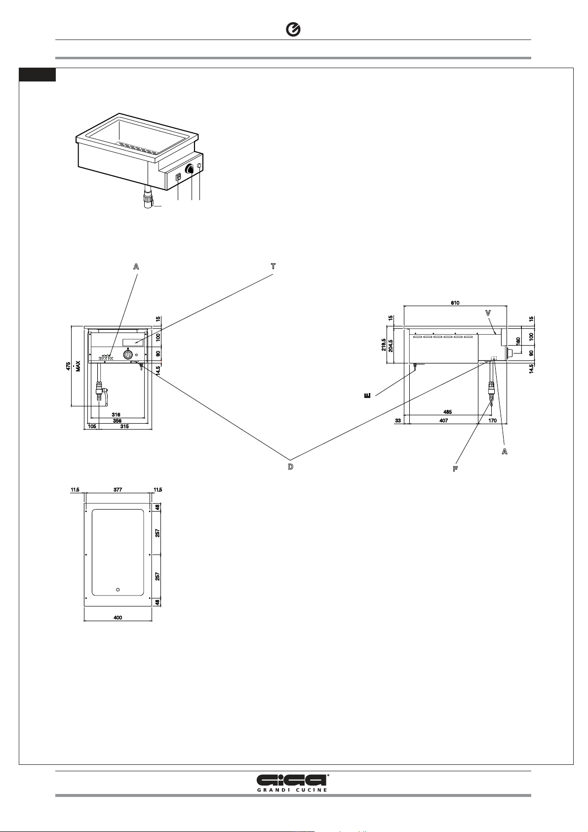
4.3.4 Wiring
Before to drop in the unit on the top, fix input cable. Electric con-
nections must be executed by qualified technician respecting rules
and regulations in force. Remove front panel unscrewing screws at
sight V (fig. 1), pass the cable through the chock-cablepress D (fig.
1) and connect wire to corresponding terminal of the terminal
board A (fig. 1), screw again.
When choosing the lead wire, make sure it has the following cha-
racteristics: it should be at least of the 07 RN-F type and its section
should be large enough for the appliance (see "Technical data").
The ground wire must be long enough to prevent tug after the
cable lead wires in case of raceway breakage.
In compliance with international regulations, when connec-
ting the appliance to the mains power supply, a device with a
minimum aperture of 3 mm between contacts must be fitted
upstream of the appliance, allowing omnipolar disconnection
of the appliance from the mains. Power switches, relays and
fuses are considered suitable separation devices.
4.3.5 Equipotential
The appliance must be hooked up to a unipotential system. The
connection screw E (fig. 1) is located at the bottom, back side.
It is labeled with the symbol .
The manufacturers cannot be held responsible for any dama-
ge due to inadequate or incorrect installation. Under such cir-
cumstances the guarantee will be considered null and void.
4.4 Preparing for installation
The electric bain-marie type INCASSO must be set on a regular
worktable, made of fireproof material and in compliance with the
current hygiene and safety standards.
It is of vital importance to observe the following instructions.
Bain-marie units can go near other appliances such as a fryer, as
long as the required distance of 50 mm (min.) is kept.
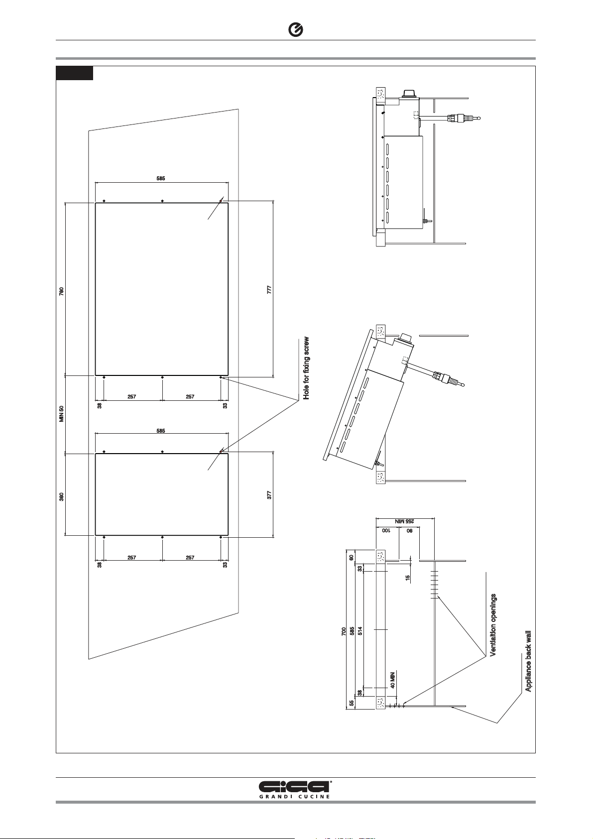
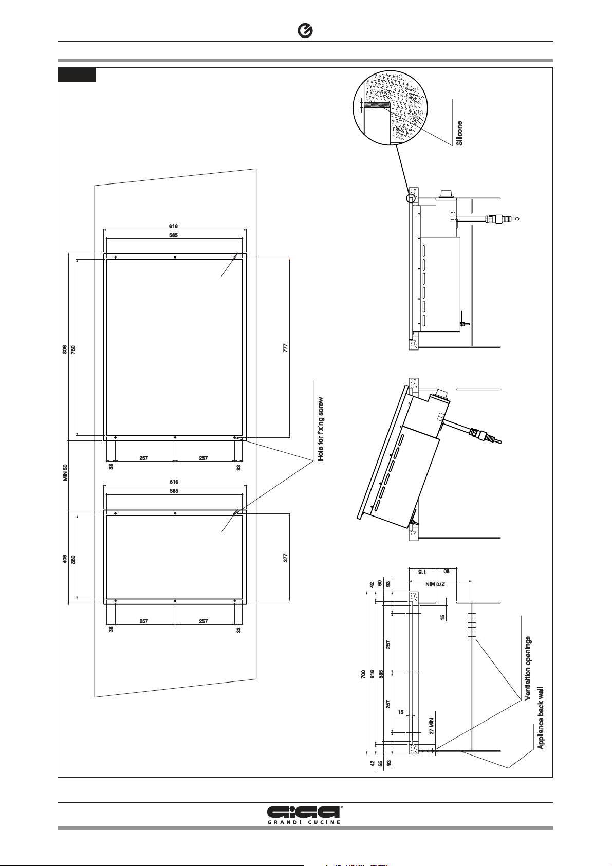
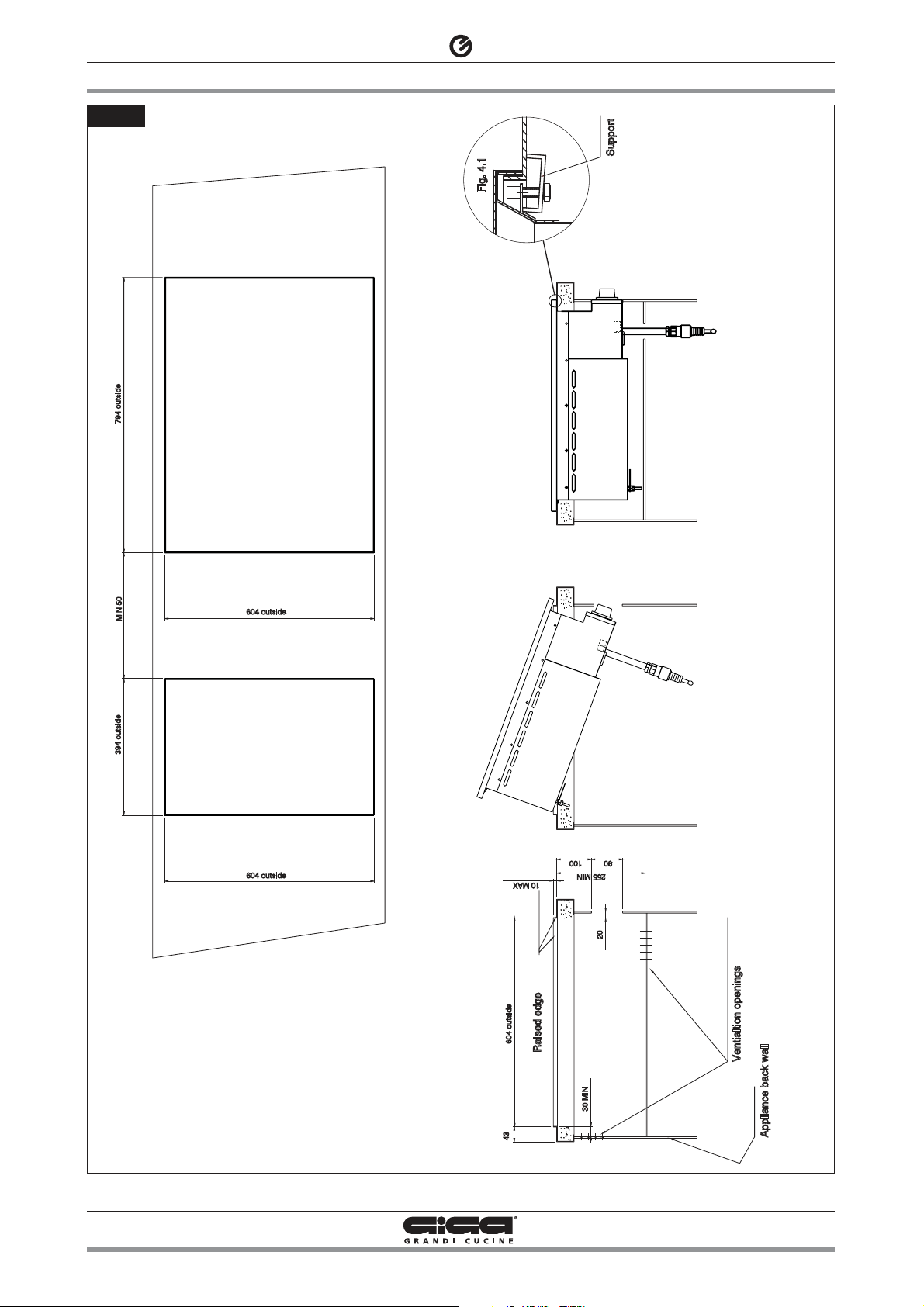
In order to install the unit properly on the worktable, proceed as
follows:
A: fig. 2) Base: With a drill, make an opening in the worktable as
described in fig. 2.
The worktable and appliance are clamped with six M5 screws; first
drill the relevant holes in the worktable as described in fig. 2. In
order to prevent liquids from leaking in between the lining and the