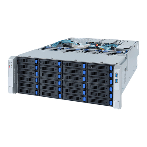
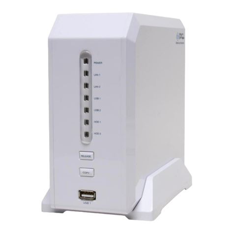
Gigabyte GS-ST000 User guide

SystemInstallation Guide
GS-ST000
Rev.1.0
25A08-0ST00-F00
Storage Server

2
GS-ST000 EntryStorage Server
TableofContent
Safety,Careand RegulatoryInformation ............................................4
Introduction ......................................................................................8
ItemChecklist ..................................................................................8
Chapter1FeatureSummary..............................................................9
Chapter2HardwareInstallation Process ..........................................10
2-1:ChassisCoverRemovaland Installation................................................. 10
2-2:CPUInstallation....................................................................................11
2-3:MemoryInstallation.............................................................................. 12
2-4:Cooling Fan Installation......................................................................... 13
2-5:PCIExpansion CardInstallation ............................................................. 14
2-6:HardDisk DriveInstallation.................................................................... 15
2-7:CD-ROMDriveInstallation .................................................................... 16
Chapter3AppearanceofGS-ST000 ................................................18
3-1:FrontViewofGS-ST000....................................................................... 18
3-2:RearViewofGS-ST000 ....................................................................... 19
3-3:FrontPanelLEDsDefinition ................................................................... 20
3-4:RearLEDsDefinition ............................................................................ 20
Chapter4SoftwareInstallation Porcess ...........................................21
4-1:SystemPartition Layout........................................................................ 21
4-2:BeforeRecovery................................................................................. 22
4-3:SystemRecoveryProcedure................................................................ 23
4-4:Recovering Screenshot........................................................................ 24
4-5:BIOSOSFailoverSetting...................................................................... 27
4-6:DefaultSetting ..................................................................................... 31
Chapter5Enterthe ManagementConsole.......................................32

3
TableofContent
Chapter6Using LCD Panel.............................................................35
6-1:LCDPanelSetting Button Introduction ...................................................... 35
6-2:LCDDisplayInformation (DisplayMode)................................................. 36
6-3:Using the LCDPanel(Setting Mode)....................................................... 36
6-4:PasswordEntering and Resetting........................................................... 37
6-4-1:Entering Password.......................................................................... 37
6-4-2:Setting Password............................................................................ 38
6-5:Returntothe MainMenu....................................................................... 39
6-6:ConfigureLANIPAddress,Netmask,Gatewayand DNS.......................... 39
6-7:WelcomeMessage Setting .................................................................... 41
6-8:DisplayTimeSetting ............................................................................ 42
6-9:ComputerInformation Menu Setting......................................................... 43
6-10:SystemTimeSetting .......................................................................... 44
6-11:Rebooting (SystemRebooting)............................................................. 45
6-12:Powering Down................................................................................. 46
Appendix.......................................................................................47
ConnectorIcon Description .......................................................................... 47
SystemMaintenanceDiagram..................................................................... 48

4
GS-ST000 EntryStorage Server
Safety,Careand RegulatoryInformation
LImportantsafetyinformation
Read and followall instructionsmarked on theproductand inthe documentation beforeyou operate
yoursystem.Retainall safetyand operating instructionsforfutureuse.
*The productshouldbe operated onlyfromthe type ofpowersourceindicated on the rating label.
*Ifyourcomputerhasavoltage selectorswitch,makesurethatthe switchisinthe properposition for
yourarea.The voltage selectorswitchissetatthe factorytothe correctvoltage.
*Theplug-socketcombination mustbeaccessibleatall timesbecauseitservesasthe maindisconnect-
ing device.
*Allproductshipped withathree-wireelectricalgrounding-type plugonlyfitsintoagrounding-type power
outlet. Thisisasafetyfeature.The equipmentgrounding shouldbe inaccordancewithlocaland national
electricalcodes.Theequipmentoperatessafelywhen itisused inaccordancewithitsmarked electrical
ratingsand productusage instructions
*Donotusethisproductnearwateroraheatsource.
*Setup the producton astableworksurfaceorsoastoensurestabilityofthe system.
*Openingsinthecaseareprovided forventilation.Donotblock orcovertheseopenings.Makesureyou
provide adequatespacearound thesystemforventilationwhen you setupyourworkarea.Neverinsert
objectsofanykind intothe ventilation openings.
*Toavoidelectricalshock,always unplug all powercablesand modemcablesfromthe wall outlets
beforeremoving covers.
*Allowthe producttocoolbeforeremoving coversortouching internalcomponents.
LPrecaution forProductwithLaserDevices
Observethe following precautionsforlaserdevices:
*Donotopenthe CD-ROMdrive,makeadjustments,orperformproceduresonalaserdeviceotherthan
thosespecified inthe product'sdocumentation.
*Onlyauthorized servicetechniciansshouldrepairlaserdevices.
LPrecaution forProductwithModems,Telecommunications,otLocalArea
NetworkOptions
Observethe following guidelineswhen working withoptions:
*Donotconnectoruseamodemortelephoneduring alightning storm.Theremaybeariskofelectrical
shock fromlightning.

5
SafetyInformation
*Toreducethe risk offire,useonlyNo.26AWGorlargertelecommunicationsline cord.
*Donotplug amodemortelephone cableintothe networkinterfacecontroller(NIC)receptacle.
*Disconnectthe modemcablebeforeopening aproductenclosure,touching orinstalling internal
components,ortouching an uninsulated modemcableorjack.
*Donotuseatelephone line toreportagasleakwhileyou areinthe vicinityofthe leak.
LFederalCommunicationsCommission (FCC)Statement
Note:Thisequipmenthasbeentested and foundtocomplywiththe limitsforaClassBdigitaldevice,
pursuanttoPart15 oftheFCC Rules.Theselimitsaredesigned toprovidereasonableprotection against
harmfulinterferencewhen the equipmentisoperated inacommercialenvironment. Thisequipment
generates,uses,and can radiateradiofrequency energyand,ifnotinstalledandused inaccordancewith
the instruction manual,maycauseharmfulinterferencetoradiocommunications.Operation ofthis
equipmentinaresidentialarea islikelytocauseharmfulinterferenceinwhichcasethe userwill be
required tocorrectthe interferenceathisownexpense.
Properlyshielded and grounded cablesand connectorsmustbe used inordertomeetFCC emission
limits.Neitherthe providernorthe manufacturerareresponsibleforanyradioortelevision interference
caused byusing otherthan recommended cablesand connectorsorbyunauthorized changesor
modificationstothisequipment.Unauthorized changesormodificationscouldvoidthe user'sauthorityto
operatethe equipment.
ThisdevicecomplieswithPart15ofthe FCC Rules.Operation issubjecttothe followingtwoconditions:
(1)thisdevicemaynotcauseharmfulinterference,and
(2)thisdevicemustacceptanyinterferencereceived,including interferencethatmaycauseundesired
operation.
LFCC part68 (applicabletoproductsfittedwithUSAmodems)
The modemcomplieswithPart68 ofthe FCC Rules.Onthisequipmentisalabelthatcontains,among
otherinformation,theFCC registration numberandRingerEquivalenceNumber(REN)forthisequipment.
You must, upon request, provide thisinformation toyourtelephone company.
If yourtelephone equipmentcausesharmtothe telephone network,the Telephone Companymay
discontinue yourservicetemporarily.Ifpossible,theywillnotifyinadvance.But,ifadvancenoticeisnot
practical,youwill be notifiedassoonaspossible.You willbeinformedofyourrighttofileacomplaintwith
the FCC.

6
GS-ST000 EntryStorage Server
Yourtelephone companymaymakechangesinitsfacilities,equipment, operations,orproceduresthat
couldaffectproperoperation ofyourequipment. Iftheydo,you willbe notified inadvancetogiveyou an
opportunitytomaintainuninterrupted telephone service.
The FCC prohibitsthisequipmenttobe connected topartylinesorcoin-telephone service.
The FCC alsorequiresthe transmitterofaFAXtransmission be properlyidentified (perFCC RulesPart
68,Sec.68.381 (c)(3)).
/forCanadian usersonly/
LCanadianDepartmentofCommunicationsCompliance Statement
Thisdigitalapparatusdoesnotexceed the Class Blimitsforradionoiseemissionsfromdigital
apparatusassetoutinthe radiointerferenceregulationsofIndustryCanada.
Le presentappareil numerique n'emetpasde bruitsradioelectriquesdepassantleslimitesapplicablesaux
appareilsnumeriquesde ClasseBprescritesdanslereglementsurlebrouillage radioelectriqueedictepar
IndustrieCanada.
LDOCnotice (forproductsfittedwithanIndustryCanada-compliantmodem)
The Canadian DepartmentofCommunicationslabelidentifiescertified equipment. Thiscertification
meansthatthe equipmentmeetscertaintelecommunicationsnetworkprotective,operationaland safety
requirements.The Departmentdoesnotguarantee the equipmentwill operatetothe usersatisfaction.
Beforeinstalling thisequipment, usersensurethatitispermissibletobe connected tothe facilitiesofthe
localTelecommunicationsCompany.The equipmentmustalsobe installedusing an acceptablemethod
ofconnection.The customershouldbe awarethatcompliancewiththeaboveconditionsmightnotprevent
degradation ofserviceinsomesituations.
Repairstocertifiedequipmentshouldbe madebyan authorizedCanadianmaintenancefacilitydesignated
bythesupplier.Anyrepairsoralterationsmade bytheusertothisequipment,orequipmentmalfunctions,
maygivethe telecommunicationscompanycausetorequestthe usertodisconnectthe equipment.
Usersshouldensurefortheirownprotection thatthe electricalground connectionsofthe powerutility,
telephone linesand internalmetallicwaterpipe system,ifresentareconnected together.Thisprecaution
maybe particularlyimportantinruralareas.
Caution:Usersshouldnotattempttomakesuchconnectionsthemselves,butshouldcontactthe
appropriateelectricinspection authority,orelectrician,asappropriate.

7
SafetyInformation
NOTICE:The Load Number(LN)assigned toeachterminaldevicedenotesthe percentage ofthe total
load tobe connected toatelephone loop whichisused bythe device,topreventoverloading.The
termination on aloop mayconsistofanycombination ofdevicessubjectonlytothe requirementthatthe
sumofthe Load Numbersofall the devicesdoesnotexceed 100.
/forEuropean usersonly/
CAUTION
vDangerofexplosion ifbatteryisincorrectly
replaced.
vReplaceonlywiththe sameorequivalent
type recommended bythe manufacturer.
vDisposeofused batteriesaccording tothe
manufacturer’sinstructions.

8
GS-ST000 EntryStorage Server
þGS-ST000 systemunitx1
þCPUcooling fan x1
þGS-ST000 SystemInstallation Guide x1
þWindowsStorage Server2003 RecoveryCD x4
þStorage ServerUser’sManual&Software&LicenseAgreementCD x1
þPowercordx1
þWindowsStorage Server2003 LicenseLabelx1
ItemChecklist
Introduction
Welcometothe GigabyteGS-ST000 EntryStorage ServerSystemInstallation Guide.The guide-
bookprovidesinstructionsforconfiguration ofGS-ST000.
Thisinstallation guidewill assisteyou ininstallingall the essentialcomponentsfortheseversystem.
Foryourprotection,pleaseread and undertand allofthe safetyand operatinginstructionsregarding your
GigabyteServerand retainforfuturereference.The proceduresinthisguidebookassumesthatyourare
asystemornetworkadministratorexperienced ininstalling similarhardware.

9
FeatureSummary
Chapter1FeatureSummary
Processor—SupportIntel®Pentium®4Celeron 2.4GHzprocessor
—400MHzFSB
—L2 cache on-dieperprocessorfrom512K
Chipset—Intel®845GVChipset
—Intel®ICH4Chipset
SystemMemory:
MemoryCapacity—2xDDR socketsup to2GB
MemoryType —Un-buffered DDR 266/333
DIMM Size—Support128MB,256MB,512MB,and 1GBmemory
Expansion Slot: —Support2xPCI32bit/33MHzadd-on cards(5V)
IntegratedLANs:
Controller—Realtek®RTL8110S
Features—1x1000BASE-T
IntegratedGraphics:
Controller—Intel®845GV
Mass StorageSystem—Support2xATAHDDs
—Support1xCD-ROM
Built-inI/O—1xSerialport(atrear)
—1xLPTport(atrear)
—4xUSB 2.0ports(2atfrontplane,2atrear)
—1xVGAconnector(atrear)
—1xRJ45 LANport(atrear)
—P/S2Keyboardand MouseConnectors(atrear)
SystemBIOS:
BIOSType —AWARD BIOS
Environment:
AmbientTemperature—Operating Temperature:5oCto35oC
RelativeHumidity—10-80%operating Humidity(no condensation)
SystemDimention:—204mm x355mm x183mm
ElectricalPowerSupply—Fixed 230Ww/PFC

10
GS-ST000 EntryStorage Server
Chapter2HardwareInstallation Process
2-1:ChassisCoverRemovaland Installation
Step 1 Loosen the chassisthumbscrews(1&2)fromthe top ofchassis,then loosethe remaning
thumbscrews(3&4).
Step 2Slide towrad tothe back ofsystemtoremovethe top chassiscover.
Step 3Slide towrad tothe back ofsystemtoremovethe side chassiscover.
Step 4ReverseStep 1,2and 3toreplacethe chassiscover.
1
Step1
Step2
2
4
Step3
3
PPriortoperforming mostkindsofmaintenance,itisnecessarytopowerdown
theserver.
Warning

11
HardwareInstallation Process
2-2:CPUInstallation
PPlease make suretheCPUtypeand speedthataresupportedbythemotherboard.
Step 1Risethe actuation leverbaron the socket.
Step 2Aligning the pinsofthe processorwiththe socket, insertthe processorintothe socket.
Step 3Closethe levercompletely.
Pin1indicator
Step2
Step1
Step3

12
GS-ST000 EntryStorage Server
2-3:MemoryInstallation
Step 1The DIMM slothasanotch,the DIMM memorymoduleonlyfitinone direction.
Step 2Align the memorynotchtothe moduleand pushthe memoryintothe DIMM socket.
Notch
Step2Step1

13
HardwareInstallation Process
2-4:Cooling FanInstallation
Step 1Cooling fan kit.
Step 2Placethe cooling fan on the top ofprocessor.Attachthe fan clip(PointA)tothe processor
socket. Attachingthe side nearestthe fan cable.Then pushdownthe remaining sideoffan clip
(PointB)tothe processorsocketuntil itlocks intoplace.
Step 3Makesurethe CPUfan cableisplugged tothe CPUfan connector,installation completed.
Step2
Step1
PointA
PointBPointA
PointB
Step3

14
GS-ST000 EntryStorage Server
2-5:PCIExpansion CardInstallation
Step 1Pull outthe releasebutton toremovethe PCIbracket.
Step 2Pushthe expansion boardintothe slotuntil the boardfirmlyseats.
RepeatStep 1&2toinstall remaining add-on cards.
Step 3Reversestep 1tocompleteinstallation.
Step2
Step1
Step3

15
HardwareInstallation Process
2-6:HardDisk Drive Installation
Step 1Press the releasebutton and pull the blankoutofthe drivebay.
Step 2Slide harddisk intoblankand secureitwithscrews
Step 3Replacethe harddriveblank,slide the blankintothe bayuntil itlocksintoplace.Connectcable
and power.
Step 4Makesurethe holeinthe blankisattached tothe system.
Step2
Step1
Step3Step4

16
GS-ST000 EntryStorage Server
2-7:CD-ROMDrive Installation
Step 1 Loosen the twochassisthumbscrewsfromthe buttomofsystem.
Step 2Removethe frontbezel
Step 3Removethe screwssecuring the dummycovertothe chassis.
Step 4Pull outthe dummycover.
Step 5Slide the CD-ROMdriveintothe bayuntil itlocks intoplace.
Step 6Pleasekeep spacebetween CD-ROMand frontbezeltoavoidthe frontbezeltotouch
CD-ROMejectbutton.
Step 7Securethe CD-ROMdrivewithscrewstothe chassis.
Step 8Connectcableand power.
Step2
Step1
Step3Step4

17
HardwareInstallation Process
Step5Step6
Step7Step8

18
GS-ST000 EntryStorage Server
3-1:FrontViewofGS-ST000
Chapter3Appearance ofGS-ST000
x
u
w
v
uLCD Panel
vPower Button
wFront LEDs
xUSB Ports

AppearanceofGS-ST000
19
3-2:RearViewofGS-ST000
u
vx
wz
{
y|
uMouse Connector
vKeyboard Connector
wParallel Port
xCOM PPort
yVGA Port
zRJ45 LAN Port
{USB Connector
|USB Connector

20
GS-ST000 EntryStorage Server
3-3:FrontPanelLEDsDefinition
ColorCondition Description
Green ONPowerOn
Green BLINK Sleep
-OFF Poweroff
Green BLINKHardDisk DriveAccess
-OFF NoAccess and NoHDD Fault
Green ONLANLink
-- OFF Idle
Name
Power
HDD
LAN
3-4:RearLEDsDefinition
ColorCondition Description
Green ONLANLink/NoAccess
Green BLINKLANAccess
-OFF Idle
YellowON1Gbpsconnection
YellowBLINK Portidentification with1Gbpsconnection
Green ON100Mbpsconnection
Green BLINK Portidentification with10 or100Mbpsconnection
Name
LAN
Link/
Activity
GbELAN
Speed
Table of contents
Other Gigabyte Network Storage Server manuals
Popular Network Storage Server manuals by other brands

Hawking
Hawking Net-Stor HNAS1 user manual

LaCie
LaCie 301138U - Ethernet Disk Mini NAS Server user manual

LaCie
LaCie 301269U - Ethernet Disk Mini Home Edition 500 GB Network Attached Storage Hard... user manual

Abus
Abus TVVR70020 user manual

Sun Microsystems
Sun Microsystems StorageTek StreamLine SL8500 System assurance guide

Buffalo
Buffalo HS-DGL Series user manual