Gigafast EF800-SI User manual

Introduction
This manual describes the installation and the
usage of EF800-SI. It features eight 10/100
Base-TX auto-negotiation switch port with
internal AC power supply, and provides the
flexibility to into your working space and
networking environment. The switch EF800-SI
can be served to connect with PCs, servers, hubs,
bridges, other switches and routers. It can also
act as a bridge between 10Mbps and 100Mbps
network segments.
Thanks to the switching technology, it support
10Mbps and 100Mbps dedicated bandwidth in
every port. The device is built with Plug &
Play, Auto-Negotiation on all ports, as well
as Half And Full Duplex Operation, Store-
and-Forward and Cut-Through transmission
mode for easy installation and smooth transition from
legacy 10Mbps to 100Mbps. One uplink port
(shared with port 1) to facilitate your network expansion.
To ensure maximum safety and good function
please read carefully and follow all the directions
in this manual to get successful Installation and
operation.
Package Contents
The EF800-SI package includes:
1 Switch, EF800-SI
This user’s manual
1 AC power cord
4 rubber foot stands
Mounting the Switch
Before installing the switch EF800-SI, be sure to
find suitable location around the center of the

devices you want to link, and near a power outlet.
Place the hub on any convenient flat surface, such
as a desktop or nearby shelf. For more stability, you
may put 4 rubber foot stands on the bottom side of
EF800-SI, if necessary.
Attach Computers to the Switch Ports
1.Install a 10/100Mabps (10/100Base-TX) network
adapter card and driver in every computer you
want to network.
2. Prepare twisted-pair cables with RJ-45 plugs.
Use Category 5/5e cable for all connections.
Make sure that the cable length is less than or
equal to 100 meters (328 feet).
3. Attach one end of the cable to the RJ-45 port of
the computer’s network adapter card and the
other end to any available port of the switch
EF800-SI. Be sure not using port 1 and the
Uplink port simultaneously.
Cascading to a Switch or another Hub
When attaching the switch EF800-SI to a router
or other devices, be sure to verify the port type
implemented before connecting any cable.
For straight-through Category 5/5e twisted –pair
cable with RJ-45 plugs:
1. Connect one end of the cable to the switch
EF-800SI’s uplink port, while keeping port 1
unplugged. Be sure follow the length limit
of 100 meter.
2. Connect the other end of the cable to any
available port, except the uplink one, of the
other devices.
For crossover cabling:
1. Connect, respectively, any two available non-
uplink pork of these 2 devices.
2. Or, connect both uplink ports of these 2
devices together.

Verify System Operation
Check each connection by viewing the port status
indicators shown in the following table. The switch
EF800-SI monitors various statuses for every port.
If there is any abnormal condition, please follow
the trouble-shooting advice detailed in the next
section.
Troubleshooting by the Diagnostic
LED Indicators
LED State Indication
Power On
Off EF800-SI is powered.
EF800-SI is not powered.
LNK/ACT On
Off
Flashing
Port has established a valid network connection.
Port has not established a valid network connection
Traffic is traversing the port.
100Mbps On
Off Port runs at 100Mbps.
Port runs at 10Mbps.
FDX/COL On
Off
Port operates in full-duplex mode or collision in
half-duplex mode.
Port operates in half-duplex mode without collision.
The operation of EF800-SI can be easily monitored
through panel LED indicators to assist the network
manager in identifying problems. This section
describes some common problems you may
encounter and together with possible solutions,
as shown in following.
Symptom: Power LED does not light up after alternating current
being
Afforded.
Cause: Defective power outlet or power cord.
Solution: Check the power outlet by plugging in another device that
functions properly. Or check the power cord with another
device.
Symptom: The LED’s, except the power one, don’t light down after
Power on.
Cause: RESET functions improperly.
Solution: Power on again.

Symptom: LNK/ACT LED does not light up after proper connection.
Cause: Network interface (e.g., a network adapter card on the
A
ttached device), network cable, or switch port is
defective.
Solution: Verify that the switch EF800-SI and the attached device
are powered. Be sure the cable is correctly plugged into
both the switch EF800-SI and the corresponding device.
Verify that the proper cable type is used and its length is
not more than 100 meter (328 feet ). Check cable
connection and the power cord for possible defects.
Replace the defective cable or cord if necessary.
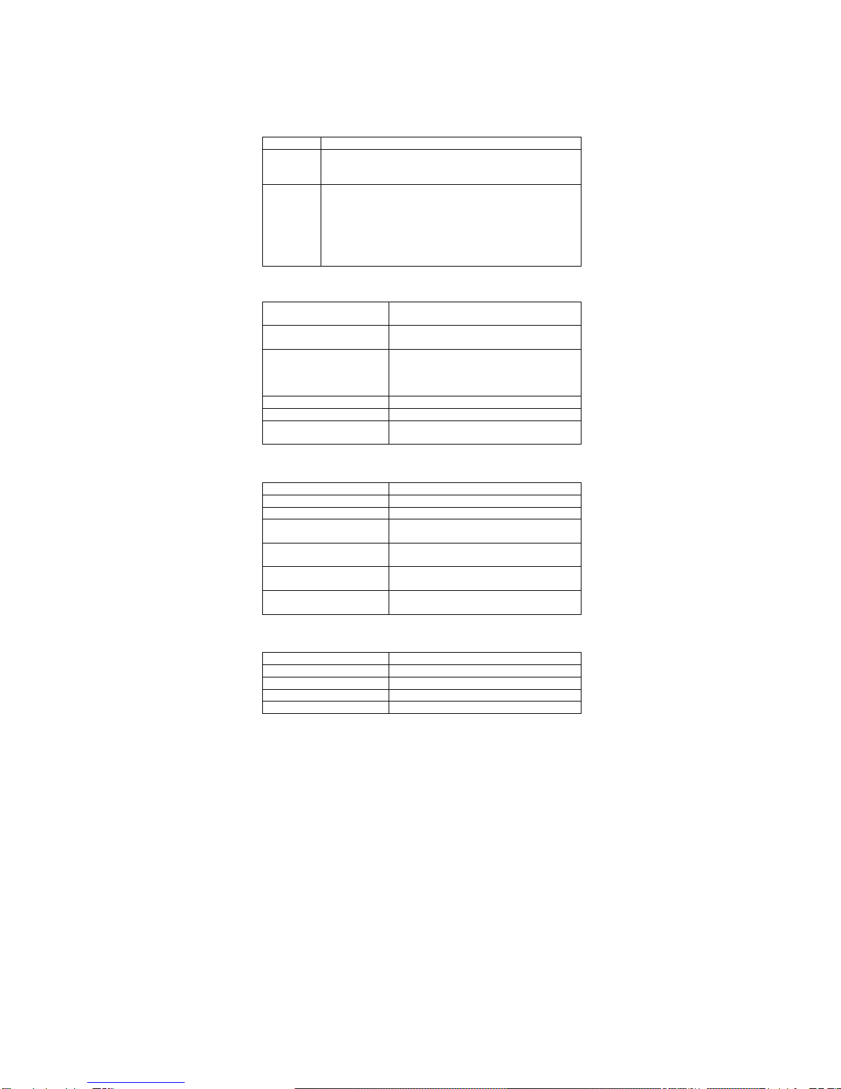
General Specification
Standard Compliance IEEE 802.3u & 802.3x 100Base-TX Fast
Ethernet, IEEE 802.3 10Base-T Ethernet
Number of Ports 8 10/100Mbps Auto-Sensing RJ-45 Ports
1 Uplink Port (Used Instead of Port 1)
Data Transfer Rate Fast Ethernet: 100Mbps (Half Duplex),
200Mbps(FullDuplex)
Ethernet: 10Mbps (Half Duplex),
20Mbps(FullDuplex)
Network Cables Unshielded Twisted-Pair Cable
Topology Star
LED Indicators Power, Link/Activity,100Mbps,Full
Duplex/Collision
Performance Specification
Transmission Method Store-and-Forward & Cut-Through
MAC Address Table 8K Entries
Packet Buffer 2M Bits Embedded DRAN
Maximum Forwarding
Rate (64byte packets) 14,8800 pps/100Base-TX
14,880 pps/10Base-TX
Maximum Filtering Rate
(64byte packets) 14,8800 pps/100Base-TX
14,880 pps/10Base-TX
Duplex Mode Supports Both Half and Full Duplex
Modes
Flow Control IEEE 802.3x (Full Duplex)
Back-Pressure (Half Duplex)
Physical & Environmental Specification
Power 100~240 VAC, 50~60Hz
Dimensions 210mmx115mmx39mm (Lxwxh)
Weight 0.7kg/1.61b
Operating Temperature 0~45 ˚C/31~113 ˚F
Humidity 10~90%(Non-Condensing)

FCC Class A Certification
Warning: This equipment generates, uses, and can
radiate radio frequency energy and, if not installed
and used in accordance with the instruction manual
may cause interference to radio communication. It
has been tested and found to comply with the limits
for a Class A digital device pursuant to Subpart B
of Part 15 FCC Rules, which are designed to
provide reasonable protection against such interfer-
ence when operated in a commercial environment
operation of this equipment in a residential area is
likely to cause interference, in which case the user,
at this own expense, will be required to take
whatever measure are required to correct the
interference.
CE Mark Declaration of Conformance
This is to certify that this product complies with
ISO/IEC Guide 22 and EN45014. It conforms to
the following specifications:
EMC: N55022(1988)/CISPR-22(1985) Class A
IEC 1000-4-2(1995) 4Kv cd,8KvAD
IEC 1000-4-3(1995) 3V/m
IEC 1000-4-4(1995) 1Kv-Power Line
0.5Kv-Signal
Line
IEC 1000-4-6(1995) 3Vrms
This product complies with the requirements of
the low Voltage Directive 73/23/EEC and the EMC
directive 89/336/EEC.
Warning
Do not plug a phone jack connector into any of the
RJ-45 port. This may damage the hub.
Table of contents
Other Gigafast Switch manuals