manuals.online logo
Brands
  1. Home
  2. •
  3. Brands
  4. •
  5. Black Box
  6. •
  7. Switch
  8. •
  9. Black Box LB620C User manual

Black Box LB620C User manual

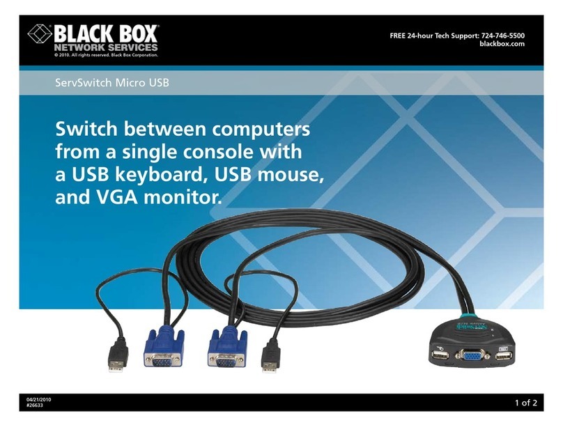
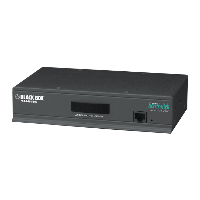
1 2 3 4
8-Port Fast Ethernet TP/Fiber
TP/SC/SCS/ST/BS Series Module
User's Manual (625−0601−000)
1. Overview
Modules of 8-Port Fast Ethernet TP/Fiber Series are used for
high-speed connection expansion in comprehensive managed
switches. Five optional module types are as below:
⎯8-Port Fast Ethernet TP Module
⎯8-Port Fast Ethernet SC Multi-Mode Fiber Module
⎯8-Port Fast Ethernet SC Single-Mode Fiber Module,
up to 80Km
⎯8-Port Fast Ethernet ST Multi-Mode Fiber Module
⎯8-Port Fast Ethernet BiDi-SC Single Fiber WDM
Module, up to 60Km
8-Port Fast Ethernet TP Module fully complies with IEEE
802.3/u/x Fast Ethernet specifications. 8-Port Fast Ethernet
Fiber Module is a 100Mbps Ethernet port that fully complies
with all IEEE 802.3u and 100Base-FX standards.
8-Port Fast Ethernet BiDi-SC Single Fiber WDM Module is
designed with an optic Wavelength Division Multiplexing
(WDM) technology that transports bi-directional full duplex
signal over a single-strand fiber.
2. Checklist
Before you start installing the Module, verify that the package
contains the following:
⎯The Module
⎯This User's Manual
Please notify your sales representative immediately if any of
the aforementioned items is missing or damaged.
3. Installing optional Modules to the
Managed Switch
The managed switch has 3 optional slots for high-speed
connection expansion.
To connect the module to the chassis:
Note: The optional modules are hot-swappable.
⇒Unscrew and remove the vacant slot dummy panel
⇒Verify that the module is the right model and conforms
to the chassis
⇒Slide the module along two guides in slot and fasten
the thumb knob, and be sure that the module is properly
seated against the slot socket/connector
⇒Install the media cable for network connection
⇒Repeat the above steps, as needed, for each module to
be installed into slot(s)
4. Fiber Transceiver Description
100Base-FX 1310nm Fiber Module Models
∗ST/SC multi-mode 2Km Option
SC.20/40/60/80Km single-mode Default (20Km)
∗∗VF-45 multi-mode 2Km ∗∗
∗∗MT-RJ multi-mode 2Km, single-mode 15Km ∗∗
∗: SC multi-mode 2Km model is option
∗∗: VF-45, MT-RJ models are available upon request
100Base-FX Single Fiber WDM Module
Mode TX, RX Wavelength
TX(Transmit) 1310nm
BS3.xx Single-Mode
Type 2 RX(Receive) 1550nm
TX(Transmit) 1550nm
BS5.xx Single-Mode
Type 1 RX(Receive) 1310nm
Note: BS3.xx and BS5.xx must be installed in pairs, i.e. install
BS3.20 at one end and BS5.20 at the other end.
5. Cabling requirements for 10/100Mbps
TP Ports
To help ensure a successful installation, you must observe the
following cabling parameter. Violating these rules can render
the LAN to work poorly.
⇒Fast Ethernet 10/100 NWay TP network connection
⎯Category 5 UTP cable and up to 100 meters
6. Cabling requirements for 100FX Module
To help ensure a successful installation, you must observe the
following cabling parameter. Violating these rules can render
the LAN to work poorly.
SC.20/40/60/80Km single mode
ST/SC multi-mode 2Km
VF-45 multi-mode 2Km
100Base-FX
1310nm Fiber
Module Models MT-RJ multi-mode 2Km, single-mode 15Km
TX(Transmit) 1310nm
BS3.20/40/60 Single-Mode
*20Km RX(Receive) 1550nm
TX(Transmit) 1550nm
100Base-FX
Single Fiber
WDM Module BS5.20/40/60 Single-Mode
*20Km RX(Receive) 1310nm
*: Default module
Fig. 1 Front View of 8-Port Fast Ethernet TP Module
Fig. 2 Front View of 8-Port Fast Ethernet SC MM Fiber Module
Fig. 6 Installation of optional modules
Fig. 3 Front View of 8-Port Fast Ethernet SC SM Fiber Module
Fig. 4 Front View of 8-Port Fast Ethernet ST MM Fiber Module
Fig. 5 Front View of 8-Port Fast Ethernet BiDi-SC Single Fiber
WDM Module
5 6
7. LED Description
LED Color Function
8-Port Fast Ethernet TP Module LED
LNK Green
Lit when connection with remote device is good
Off when cable connection is not good
ACT/
FDX/
SPD
Amber
a. LEDSET set on ACT (active) mode:
Blinks when any traffic is present
b. LEDSET set on FDX (full-duplex) mode:
Lit when full-duplex mode is active
Blinks when any collision is present
c. LEDSET set on SPD (speed) mode:
Lit when 100Mbps speed is active
Off when 10Mbps speed is active
8-Port Fast Ethernet Fiber Module LED
LNK Green
Lit when connection with remote device is good
Off when cable connection is not good
ACT/
FDX/
SPD
Green
a. LEDSET set on ACT (active) mode:
Blinks when any traffic is present
b. LEDSET set on FDX (full-duplex) mode:
Lit when full-duplex mode is active
Blinks when any collision is present
c. LEDSET set on SPD (speed) mode:
Lit when 100Mbps speed is active
Off when cable connection is not good
8. Technical Specifications
Fiber Connector:
100Base-FX:
1310nm ST, SC, MT-RJ, VF-45 multi-mode
1310nm SC, BiDi, MT-RJ single-mode
100Base-FX Single Fiber:
TX(Transmit) 1310nm
BS3.20/40/60 Single-Mode
SC *20Km RX(Receive) 1550nm
TX(Transmit) 1550nm
BS5.20/40/60 Single-Mode
SC *20Km RX(Receive) 1310nm
* : Default module
Standards:
IEEE802.3/802.3u
IEEE802.3x and 802.3ab
100Mbps Ethernet 100Base-FX
Transmission Speed and Mode:
10/100Mbps for TP(full/half duplex)
100Mbps for Fiber(full/half duplex)
Fiber Optic Cable:
62.5/125, 50/125
μ
m multi-mode
9/125
μ
m single-mode
Network Interface:
Configuration Mode Connecto
r
Slot
10/100Base-T Copper Module NWay TP (RJ-45) 3(Option)
100Base-FX 100Mbps Fiber Module 100FDX/
HDX *SC/ST
M-M 3(Option)
100Base-FX 100Mbps Fiber Module 100FDX/
HDX *SC S-M 3(Option)
100Base-FX Single Fiber WDM Module 100FDX/
HDX *BiDi-SC
S-M 3(Option)
* : Default module
Full Forwarding/Filtering Packet Rate:
PPS (packets per second)
Forwarding Rate Speed
148,800PPS 100Mbps
14,880PPS 10Mbps
Flow Control:
IEEE802.3x compliant for full-duplex
Backpressure flow control for half-duplex
Diagnostic LED :
Per Port LED :
10/100M TP Module : Link, ACT/FDX/SPD
100M Fiber Module : Link, ACT/FDX/SPD
Cable and Maximum Length:
TP Cat. 5 UTP cable, up to 100m
100Base-FX SC S-M Single-Mode Fiber, up to
20/40/60/80Km
100Base-FX WDM
BiDi-SC S-M Single Fiber, BiDi , up to
20/40/60Km
Ambient Temperature : 0°to 40°C
Humidity : 5% to 90%
Fiber Module Dimensions : 44(H) ×122(L) ×82(W) mm
TP Module Dimensions : 44(H) ×122(L) ×71(W) mm
Complies with FCC Part 15 Class A and CE Mark
Note: For connecting this device to Router, Bridge or
Switch, please refer to the corresponding device's
Technical Manual.

This manual suits for next models

1

Other Black Box Switch manuals

Black Box KV1702A User manual

Black Box

Black Box KV1702A User manual

Black Box LGB2004A User manual

Black Box

Black Box LGB2004A User manual

Black Box ServSwitch KV5004MN-R2 User manual

Black Box

Black Box ServSwitch KV5004MN-R2 User manual

Black Box LGB5028A User manual

Black Box

Black Box LGB5028A User manual

Black Box JPM816A-HD User manual

Black Box

Black Box JPM816A-HD User manual

Black Box LGB1108A User manual

Black Box

Black Box LGB1108A User manual

Black Box KV6416FA-R2 User manual

Black Box

Black Box KV6416FA-R2 User manual

Black Box SW1033A User manual

Black Box

Black Box SW1033A User manual

Black Box LGB304A User manual

Black Box

Black Box LGB304A User manual

Black Box LBH3050A User manual

Black Box

Black Box LBH3050A User manual

Black Box SW1020A User manual

Black Box

Black Box SW1020A User manual

Black Box AC447A User manual

Black Box

Black Box AC447A User manual

Black Box ICI104A User manual

Black Box

Black Box ICI104A User manual

Black Box LBG1000A-R2 User manual

Black Box

Black Box LBG1000A-R2 User manual

Black Box Active Star Hub IC207A User manual

Black Box

Black Box Active Star Hub IC207A User manual

Black Box LGH1004A User manual

Black Box

Black Box LGH1004A User manual

Black Box SW546A User manual

Black Box

Black Box SW546A User manual

Black Box PSE508MA User manual

Black Box

Black Box PSE508MA User manual

Black Box KV9004A User manual

Black Box

Black Box KV9004A User manual

Black Box LB9006A-SC User manual

Black Box

Black Box LB9006A-SC User manual

Black Box KV9316A-R2 User manual

Black Box

Black Box KV9316A-R2 User manual

Black Box ACU7017A User manual

Black Box

Black Box ACU7017A User manual

Black Box SW590A-R2 User manual

Black Box

Black Box SW590A-R2 User manual

Black Box IC1020A User manual

Black Box

Black Box IC1020A User manual

Popular Switch manuals by other brands

Lantech LES-2400-RPS user manual

Lantech

Lantech LES-2400-RPS user manual

H3C H3C S5600 Series Operation manual

H3C

H3C H3C S5600 Series Operation manual

Artistic Licence Rail-Switch II user guide

Artistic Licence

Artistic Licence Rail-Switch II user guide

Chamberlain RZ94-05 instruction manual

Chamberlain

Chamberlain RZ94-05 instruction manual

Sandberg 135-52 quick start guide

Sandberg

Sandberg 135-52 quick start guide

ATEN CN9900 quick start guide

ATEN

ATEN CN9900 quick start guide

Lucent Technologies Cajun P550 Guide Cli reference guide

Lucent Technologies

Lucent Technologies Cajun P550 Guide Cli reference guide

Raritan PX3TS user guide

Raritan

Raritan PX3TS user guide

NIVOFLOAT NL-100 Series user manual

NIVOFLOAT

NIVOFLOAT NL-100 Series user manual

RCA Digital Plus DH4CVS user manual

RCA

RCA Digital Plus DH4CVS user manual

SJE Rhombus VERTICALMASTER Installation and operating instructions

SJE Rhombus

SJE Rhombus VERTICALMASTER Installation and operating instructions

Cypress CHMX-24 Operation manual

Cypress

Cypress CHMX-24 Operation manual

Neol ePowerSwitch-1 Guard user guide

Neol

Neol ePowerSwitch-1 Guard user guide

IOGear GWFRSDU user manual

IOGear

IOGear GWFRSDU user manual

Dell PowerConnect W-IAP175P Quick setup guide

Dell

Dell PowerConnect W-IAP175P Quick setup guide

Hama Deluxe 210 operating instructions

Hama

Hama Deluxe 210 operating instructions

H3C S5130S-EI series installation guide

H3C

H3C S5130S-EI series installation guide

Honeywell PLS731B Installation and user guide

Honeywell

Honeywell PLS731B Installation and user guide

manuals.online logo
manuals.online logoBrands
  • About & Mission
  • Contact us
  • Privacy Policy
  • Terms and Conditions

Copyright 2025 Manuals.Online. All Rights Reserved.