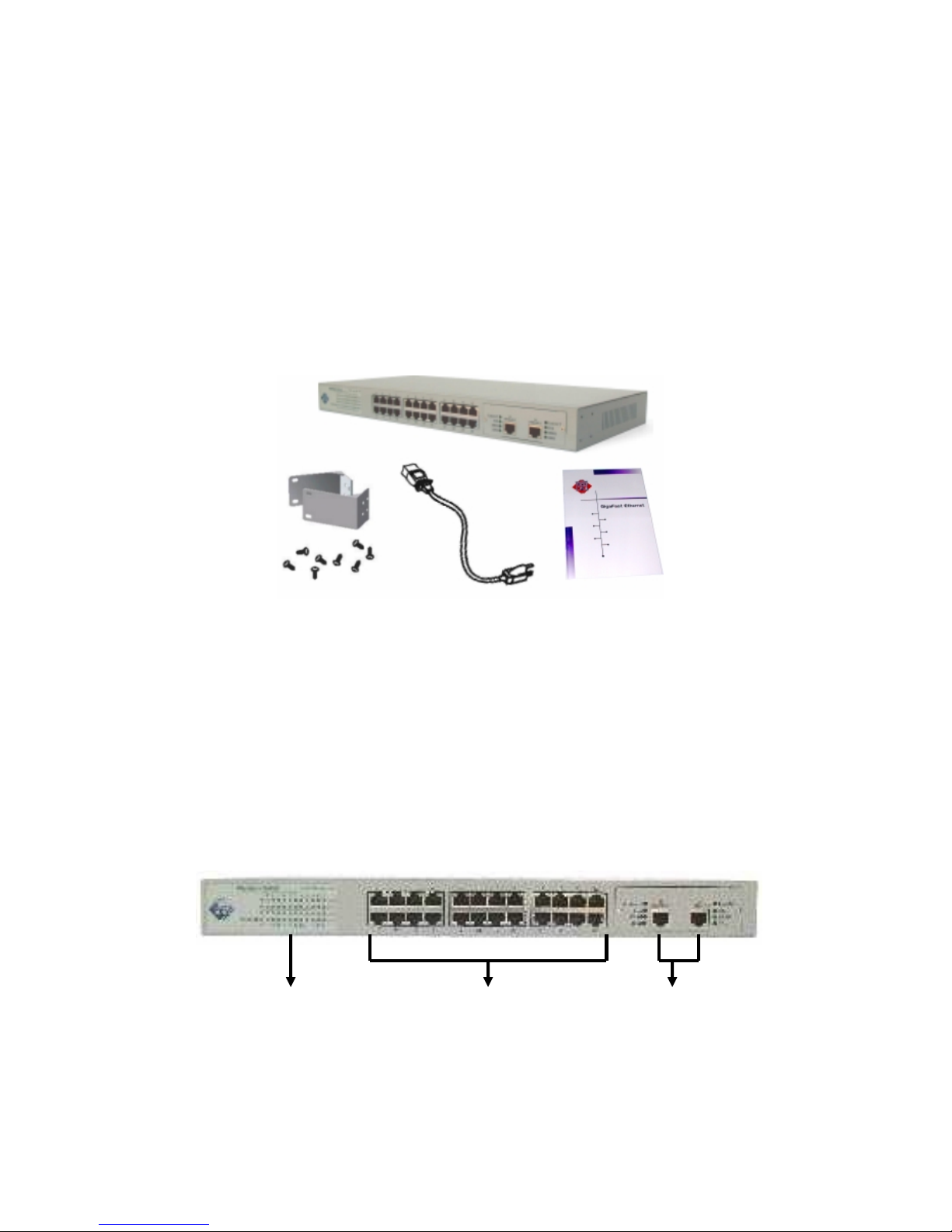
Gigafast EE2400-G User manual

1. Introduction
The Fast Ethernet Switch with Gigabit modules is an auto-sensing
10/100Mbps switch with two build-in 10/100/1000 Gigabit ports. This
high-performance switch is developed primarily to be used either as a
segment switch or a desktop switch.
Thus, EE2400-G can provide up to 2 additional Gigabit ports for 2 gigabit
backbone connections within your Local Area Network (LAN).
All of the network ports on the Model EE2400-G can adapt automatically to
the speed of the connected network or the PC, and ports can operate at
either 10Mbps or 100Mbps. In addition, each port can automatically negotiate
with the connected device to operate in full-duplex mode. If the connected
device is operating in half-duplex mode only, or does not have the capability
to participate in the negotiation process, the port will default to half-duplex
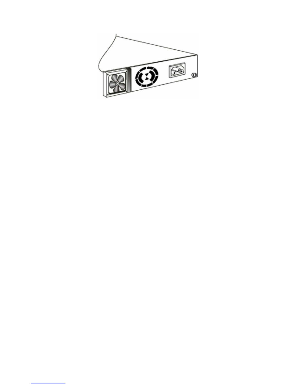
mode. The BaseSwitch EE2400-G supports basic management function
(Console management). Console management involves the RS-232 console
port. The functions of the console management include Trunk Setting, VLAN
Setting, and Priority etc.
EE2400-G is compliant to 10/100/1000BASE-T standards. It operates in a
protocol-independent manner, eliminating the overhead for management
software and maintenance efforts. Furthermore, it features up to 2
Copper-wired gigabit ports to enable Gigabit backbone connections for
departmental workgroups or high performance servers. LAN users can very
easily upgrade their existing Ethernet/Fast Ethernet to Gigabit networking
environment. With easy Plug-and-Play installation, EE2400-G Gigabit
Ethernet Switch offers you an effortless and inexpensive upgrade to Gigabit
network.
There is a console port at the rear panel of this EE2400-G. User can setup
per-port 10/100Mbps, Half/Full duplex configuration from the console port.
The VLAN、Trunking and Priority functions of EE2400-G is also setup from
the console port. Users can setup VLAN groups for network management or
user can setup trunking connection for switch-to-switch connection with faster
bandwidth.

Product Features
▪24+2-port Gigabit Ethernet Switch with 2 build-in Gigabit Ports
▪Two auto-negotiating 10/100/1000 Mbps UTP ports which support 10/100
Mbps or 1000Mbps full-duplex with standard RJ-45 connectors.
▪Auto negotiation supported by all 10/100 Mbps and Gigabit ports
▪Supports IEEE802.3x flow control in full duplex and back pressure in half
duplex to prevent packet loss
▪Automatic address-learning function to build the packet-forwarding
information table
▪Supports two built-in Gigabit Copper ports
▪Non-Blocking 9.6Gbps aggregate throughput
▪Auto MDI/MDI-X Switching
▪One Console port on the rear side for VLAN、Trunking & Priority
Configuration
▪Aging function to automatically track changes in network configuration
▪Store-and-forward mode to minimize erroneous packets on the network.
▪Easy Plug and Play installation with no software to configure, saving time
and minimizing the potential for configuration errors
▪Rack Mount Kit provided for installing the switch in a standard 19-inch
equipment rack, or for mounting on the wall
▪Conformity to standards:
-IEEE 802.3 10BASE-T standard
-IEEE 802.3u 100BASE-TX standard
-IEEE 802.3ab 1000BASE-T standard
-IEEE 802.3x flow control
Disclaimer
All Trademarks belongs to their respective owners. GigaFast cannot be held
responsible for any damage made during the installation. GigaFast also reserves the
right to modify the manuals without notice. GigaFast is not responsible for typos,
misprints or grammatical errors on the manual or product boxes.

Table of Contents
Chapter 1 Introduction
Product Features
Chapter 2 Preparation before Installation
CheckingPackageContents
TheFrontPanel
TheRearPanel
Chapter 3 Installation of the Switch
QuickInstallation
Chapter 4 Configure the Switch
Configure the Network Connection
Configure the Switch from the Console Port
Application
Chapter 5 LED’s Defined
Appendix A Product Specifications

2. Preparation before Installation
2.1 Package Contents
●One 26-port 10/100/1000Mbps Ethernet Gigabit Switching Hub
●One AC power Cord
●Two Rack-mount kits and screws
●Four self-adhesive rubber foot pads
●This installation guide
2.a Package Contents
The Front Panel
The front panel is where you can find the 24 10/100Mbps station ports
(MDI-X), two build-in Gigabit ports and LED indicators. For the technical
specifications of the ports, please refer to Product Specifications in Appendix
A for detailed information. For information concerning LED indicators, please
refer to Chapter 6: LED Indicators.
2.b Front Panel
LED Indicators Station Port Gigabit Port

The Rear Panel
The rear panel is where you can locate the power switch, AC power connector,
ventilators and console port.
2.c Rear Panel
AC Power Connector
This is a three-pronged power connector where the power cord should be
attached. Just plug the female end of the power cord into the connector, and
the male end of the power cord into an AC power outlet. The switch supports
an input voltages ranging from 100~240V at 50~60 Hz.
Ventilators
These two ventilators fans help circulate the cool air through the heated
components inside the switch. The air holes on both sides of the switch also
serve as heat vents to dissipate the heat. For proper ventilation, please be
careful in your installation that in any case these openings should not be
blocked. An adequate margin space for the rear and both sides of the switch
should be provided. Be reminded that without proper air circulation to
dissipate the heat, the internal components of the switch might get
overheated, which might lead to system failure.
Each cooling fan is housed in a fan tray, which ensures its proper functioning
without getting entangled with external wirings or improper tempering. The
cooling fans are endurable and work reliably to prevent your switch from
overheating. Since the switch is equipped with two cooling fans, heat
dissipation can still function if one fan stops running. But if you find either fan
not functioning properly, please contact your local dealer for replacement.
Console Port Ventilator Power Connector

2.d Cooling Fan housed within fan tray
2.2 Where To Place the Switch
This 24-port gigabit Switch can be placed on a flat surface (your desk,
shelf or table) or mounted onto a rack.
Place the 24-port gigabit Switch at a location with these connection
considerations in mind:
●The switch is accessible and cables can be connected easily to it
●The cables connected to the switch are away from sources of electrical
interference such as radio, computer monitor, and light fixtures.
●There is sufficient space surrounding the hub to allow for proper
ventilation (the hub may not function according to specifications beyond
the temperature range of 0 to 40 degrees C)

3. Installation of the Switch
Preparation before Installation
Before you being installing the EE2400-G; prepare the installation site. Make
sure that you have all the necessary components that come with your
package. Follow the step below to unpack your package contents:
1. Clear out the surrounding area for an adequate space to unpack the
package carton.
2. Open the shipping carton and take out the package contents carefully.
3. Put back all the shipping materials such as plastic bag, pads and linings
into the shipping carton and save them for possible future transport need.
After unpacking and taking out all the components, you should check package
contents, unpack the contents of the package and verify them against the
following list:
▪EE2400-G Gigabit Ethernet Switch
▪Self-adhesive rubber footpads for desktop installation
▪Rack Mount Kit for rack installation
▪One AC power cord
▪This installation guide
◘Caution: Use the appropriate power cord as required by your national
electrical code and ordinances.
Call your reseller or customer support in your area if there are any
wrong, missing, or damaged parts. Refer to the enclosed
Customer Support Information Card for more information.
Installation of the Switch
Quick Installation:
1. Install self-adhesive rubber footpads on the bottom of the switch
2. Connect to power: Check the integrity of the power cord to see if it is in
good condition and ready for use. Use the power chord to connect the
Switch and AC Power outlet on wall. Powered on the Switch.
3. Connect your Gigabit port with appropriate cable. You must use a
twisted-pair cable to connect the copper-wired gigabit port.

Installing the Switch in a Rack
To mount the switch in a standard 19-inch equipment rack, you need these
tools and materials:
▪Two mounting brackets supplied from the Rack Mount Kit
▪Eight screws supplied from the Rack Mount Kit
3-a Fastening the brackets on the switch
To install the switch in a rack:
1. First, align the holes on the bracket with the holes on both side of the
switch.
2. Insert screws into the holes and then fasten the bracket on one side of the
switch with a screwdriver.
3. Repeat Step 1 and 2 to fasten the bracket on the other side of the switch.
4. Mount the unit on the rack and align the notches on both brackets with
mounting holes on the rack, and then secure the unit with suitable screws.
3-b Mounting the Switch onto a Rack
Desktop Installation
1. Install self-adhesive rubber footpads on the bottom of the switch; peel of
the protective backing from the rubber pads and apply one at each marked

location on the bottom of the switch.
2. Set the switch on a desktop or any other flat surface; for proper ventilation,
make sure that the switch has at least 2 inches of space on each side and
5 inches of space at the back. It is very important that the fans located in
the rear panel are not blocked.
◘Caution: Restricted airflow could cause overheating of the components.
3-c Desktop Installation
Installation Site Preparation
You can mount EtherEngine2400-G Gigabit Ethernet Switch either on a table
or on a standard-size rack. If you plan to mount the switch on the table,
please choose a steady, level surface in a well-ventilated area that is free
from excessive dust. In any case, the installation site chosen for your switch
has to comply with the following requirements:
The surface where you want to mount the switch must be able to sustain
at least 3.8kg.
Do not place heavy objects on top of the switch
The location must preferably be free from excessive dust, away from
heat vent or other warm-air exhaust and direct sunlight. The switch
should not be placed near large electric motors or other electromagnetic
equipments. As a reference, the strength of the electromagnetic field on
site should not exceed the (RFC) standards for IEC 801-3, Level 2 (3V/M)
field strength.
The air temperature in the location should be within a range of 32˚F to
122˚F (0˚C to 55˚C).
The relative humidity in the location should not exceed 95%
non-condensing humidity.
The power outlet should be located within 6 feet from the device.
The distance between the RJ-45 port and the standard network interface
should not exceed 100 meters.

Adequate space should be allowed in front of all the ports, so that each
port is easily accessible for cable connections.
Cabling Requirements
EtherEngine 2400-G Gigabit Ethernet Switch is primarily designed as a
central switching device to provide congestion-free bandwidth to your existing
10/100/1000Mbps network. It can also provide you with up to 2 gigabit
backbones to relieve your network bottleneck. It fits well into the
10/100/1000BASE-TX cabling architecture to facilitate not only 20/200Mbps,
but also 2000Mbps full-duplex transmission speed. The auto-detecting MDI
Uplink will automatically change the regular port to an uplink port that
provides a switch-to-switch cabling extension up to 100 meters.
The table below describes which types of cable should be used in which
circumstances:
10/100/1000BASE-T connection
The 24 RJ-45 station ports (MDI-X) and the copper-wired gigabit port require
either UTP or STP cable for connection. When configuring within the
10/100/1000BASE-T cabling architecture, the UTP cabling distance should be
within a maximum distance of 100.
RJ-45 station port cable requirements:
●10BASE-T
100 ohm Category 3, 4 or 5 unshielded or shielded twisted-pair (UTP/STP)
cables.
●100BASE-TX
100 ohm Category 5 UTP/STP cables.
Connection
Specification
Station Port (10BASE-T/100BASE-TX)+
Copper-wired Gigabit Port 1000BASE-T
Port RJ45 Port
To an end station Straight-through
Twisted-pair cable
To a hub/switch Straight-through
Twisted-pair cable
Maximum Distance 100M

RJ45 Gigabit port cable requirements:
●1000BAST-T
100 ohm Category 5 UTP/STP cables.
Straight-through/crossover cabling requirements
Under most conditions, the 24 station ports on the Switch may accept normal,
straight-through cables, i.e., standard UTP/STP cables, which are the only
ones that can be used with a RJ-45 pin layout.
Normally, 10BASE-T networks require a straight-through Cat. 3,4,5 UTP/STP
cabling system. The cabling system could be found in most existing network
installations. 100/1000BASE-T networks require Cat 5 UTP/STP cabling
system.
3-d 10/100BASE-TX pin assignments for RJ-45 connector
Adapter Switch
1 1
2 2
3 3
4 4
5 5
6 6
7 7
8 8
Cable and Connector

3-e Pin Assignments for straight-through cabling
In some circumstances, however, crossover cables may be required. If a
station port on your switch must connect to a hub/switch, you must use a
crossover cable, which ha sits transmit (TD) and receive (RD) leads crossed
over to the other end of the cable.
Note:
The pin RJ-45 assignment used in 1000BASE-T is different from in
10/100BASE-TX. Therefore, a Switch-to-Switch 1000BASE-T connection
does not require a crossover cable.
However, the 1000BASE-T gigabit port can automatically determine whether
or not it needs to cross over between pairs. Therefore, the 1000BASE-T
gigabit port does not require an external crossover cable when connecting to
another Switch.
If EE2400-G interoperates with a device that cannot automatically correct for
crossover, it makes the necessary adjustment prior to commencing
auto-negotiation. If it interoperates with a device that implements MDI/MDIX
crossover, a random algorithm as described in IEEE802.3 section 40.4.4
determines which device performs the crossover.
3-f 10/100BASE-TX pin assignments for crossover cabling

Connecting to Power
EE2400-G Gigabit Ethernet Switch features a universal auto-select power
supply unit, which allows a power connection to a wide range of input
voltages from 90 to 240V AC @ 50 to 60 HZ.
To establish its power connection, simply plug the female end of the power
cord into the power connector on the rear of the switch and the male end of
the power cord into a suitable power outlet. Once you have correctly plugged
in the power, you can then turn on the Power Switch to activate the switch.
3-h Connecting the Switch to Power outlet
Power Connector
Power Cord
Table 3-g 1000BASE-T pin assignments for RJ-45 connector

4. Expanding Your Network
EtherEngine 2400-G Gigabit Ethernet Switch is primarily targeted not only as
a central switching device to manage you workgroup/departmental traffic
within Ethernet/Fast Ethernet; but it also can provide up to 2 gigabit
backbones to relieve your network bottleneck. With your existing
Ethernet/Fast Ethernet infrastructure, you can very easily connect, expand or
migrate your existing Ethernet/Fast Ethernet networks to gigabit networking
environment.
The following sections will introduce to you the basics of network connectivity
in workgroup/departmental computing within Ethernet/Fast Ethernet/Gigabit
Ethernet environment.
Connectivity Rules
10/100 Mbps Connection (10BASE-T/100BASE-TX)
Ethernet connection should be configured according to the following
connectivity rules:
The maximum length for UTP cables must not exceed 100 meters from
end station to a shared-access 10BASE-T/100BASE-TX hub.
Between any two end stations in a collision domain, there may be up to
five cable segments and four intermediate repeaters at most.
If there is a path between any two end-stations containing five segments
and four repeaters, then at least two of the cable segments must be
point-to-point link segments (e.g. 10BASE-T, 10BASE-5), while the
remaining segments may be of mixed segments (e.g.: 10BASE-2 or
10BASE-5).
Copper-wired10/100/1000Mbps
Connection(10/100/1000BASE-T)
Copper-wired Fast Ethernet/Gigabit Ethernet connection should be configured
according to the following connectivity rules:
The maximum length for STP/UTP cables is 100 meters from end station
and a shared-access 100BASE-TX hub.
The 26 Port 10/100/1000Mbps N-Way Auto-negotiating gigabit Switch
can be used to build or increase the bandwidth on a network.
EE2400-G Gigabit Ethernet Switch allows a 10BASE-T or 100BASE-TX hub
to be connected to the Switch via a 4-pair UTP/STP straight-through cable

(Category 3, 4 or 5). Each cable length can be up to 100 meters long (328
feet ). The hub-to-switch connection is daisy-chain port (MDI-II) on the hub to
any of the station ports (MDI-X) on the Switch.
For a 10BASE-T or 100BASE-TX hub, the LED indicators on the Switch
should give the following signals to indicate a proper connection:
Link/Act LED indicators should be ON at green color
FDX/COL Led indicators should be ON at green color
10/100M LED indicator should be ON if connected to 10BASE-T on red
color , if connected to 100BASE-TX on green color 100BASE-TX,
otherwise it should be OFF
Switch-to-Switch Connection (10/100BASE-TX)
EE2400-G Gigabit Ethernet Switch can be connected to another switch or
other device, such as a router or bridge by a two-pair UPT/STP
Straight-through or Crossover cable (Category 3, 4, 5).
Using a Straight-through Cable
When using a straight cable, the switch-to-switch connection is done through
the daisy-chain port (MDI-II) of the Switch to any of the 10Mbps or 100Mbps
station port (MDI-X) of another switch or device.
Using a Crossover Cable
When connecting any 10/100Mbps station port (MDI-X) of other switch or
device to any station port (MDI-X) of EE2400-G Gigabit Ethernet Switch, it is
required that you use a crossover cable.
RJ-45 Gigabit Port Description
The RJ-45 Gigabit port can automatically determine whether it needs to cross
over between pairs . Therefore, the 1000BASE-T gigabit port does not require
an external crossover cable when connecting to another switch.

4-a 1000BASE-T pin assignments for RJ-45 connector
Summary:
When connecting a computer to the station port/gigabit port of the Switch,
use a straight-through UTP cable.
When connecting the gigabit port of EE2400-G to the station port of a
hub/switch, use a straight-through cable.
When using crossover cable, the connection can be made from any
station ports (MDI-X) of EE2400-G to any station ports (MDI-X) of other
Switch.
Applications:
EE2400-G Gigabit Ethernet Switch serves primarily as a backbone switch to
connect your existing Ethernet/Fast Ethernet network to Gigabit networking
environment. EE2400-G can provide up to 2 gigabit backbones to connect to
another gigabit switches or high-end servers. With gigabit bandwidth,
backbone traffic can be greatly improved for the ever-increasing bandwidth
demand by the internet/intranet multimedia application.
After you have set up the Ethernet/Fast Ethernet portion of your network, or if
you have already got an existing Ethernet/Fast Ethernet network, you can
then directly connect to the Gigabit network using EE2400-G.
The Copper connection can either serve as a high-bandwidth backbone to
connect with other network segments, or as a connection to high-performance
server. With the exceptional bandwidth provided by the gigabit connections,
the network traffic can be greatly improved.

EE2400-G provides such a cost-effective way to gear up your network
performance to gigabit bandwidth. In addition, you will appreciate the easy
plug-and-play function of its installation within your network.
The high-performance server needs a high-bandwidth throughput, you may
consider upgrade to a server-to-switch gigabit connection, together with a
Gigabit NIC card.
The gigabit connection can be easily implemented and cost you virtually no
effort to configure and maintain. After you’ve properly connected to the gigabit
networking environment, you’ll appreciate the powerful bandwidth and the
cost-effective migration EE2400-G Gigabit Ethernet Switch offers to you.
Internet
Router
EE2400-G
EE2400-G
GE-2000N
10Mbps Hub
100Mbps Hub
Gigabit backbone
2000Mbps bandwidth
VLAN1
100Mbps Segment10Mbps Segment
VLAN2
File
Server
Printer
Gigabit backbone
2000Mbps bandwidth
10/100/1000 BASE-TX
EE2400-S

5. Configure the Switch
Configure the Switch from the Console Port
〔1〕Setup Hardware and Software for configuration
〔Hardware setup〕
Connect from the console port (at rear panel) of the Switch to COM port
of PC with the RJ45-DB9 adapters and one network cable, or standard
RS232 cable.
〔Software setup〕
1. PC is running Win95/98/NT.
2. Start→Program→Accessory→Terminal. Execute "Hypertrm"
program
3. If the connection file has been created, cancel he new connection
request and open the connection file. If the connection file has not
been created, create a new connection named "EE2400G"→Select
COM port of PC→Set COM port parameters as "Baud Rate:9600,
Data Bits: 8, parity Check: None, Stop Bit:/, Flow Control: None"
Then OK.
4. Power on the Switch and the setup console will appear as follow:
5. Enter “ 1” for Port Setup.

〔2〕Configure Connection Ports of the Switch
1. Users can enable/disable the auto-negotiation function of the
connection ports with this function. If the auto-negotiation is
disabled, users can set the connection speed, full/half duplex of
the connection ports. The default setting is auto-negotiation
enable.
2. Follow the direction in the setup menu to setup the configuration of
the Connection ports.
3. Select Port number 1~24
4. Press “ 5” for select 10M_HDX Mode

5. The indicators of the display panel of the Switch may ON/OFF
depend on the setting of the ports in this function when the
cables are link connected.
〔3〕Setup VLAN Groups of the Switch
1. Enter the VALN setup function in the setup console as follow.
2. All of the connection ports are in the same VLAN group default.
3. Users can add / modify / remove connection ports to/from VLAN
group.
Table of contents
Other Gigafast Switch manuals