Guidelines/ Manual
BTS256-LEDTester/ Page6
AboutLEDMeasurement
Version 01.2009-01
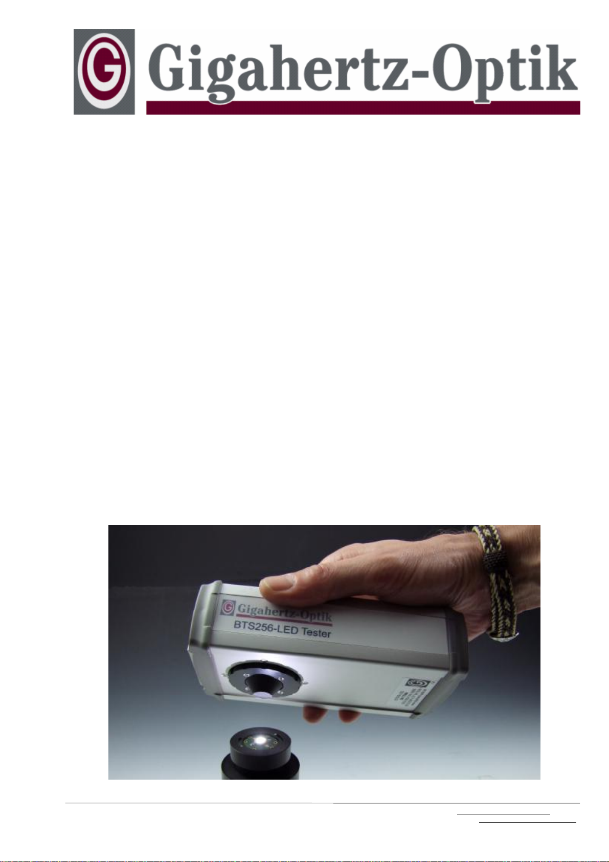
Picture6.1:
WhiteLEDAssembled toDUTPCBofGigahertz-Optik’s
LEDA2LEDMeasurementAdaptersimulating Application
ConditionsDuring Qualification Measurement
TheBTS256-LEDtesterisalightmeasurementdevicees-
peciallydesignedtoanalyzethelightoutputofprintedcir-
cuitboard(PCB)mountedand operatedLightEmitting Di-
odes(LED).
Basics ofLEDMeasurements:
LEDs aresemiconductorlight sourceswithahigh efficiency
electricalpowertolightpowerconversion.Aswithany
semiconductordevice,operating temperatureeffects
changesinperformancereferredtoasadevice’stempera-
turecoefficient. Inconnection withLEDsthetemperature
coefficientwilleffectareduction inlightoutputand adriftin
color.Operation underhigh junction temperatureconditions
mayeffectlifetime.Certainambientoperating environ-
ments,e.g.high humidity,canimpactlifetimeand device
specificationsaswell.Thermalmanagementisofprimary
importancetothesuccessfulimplementation of LEDs.
Sorting orgrading ofindividualLEDsbycolordifferences
caused bytolerancesinthe semiconductorprocessisa
common practiceoffered bymostsemiconductormanufac-
turers. But duetodiffering LEDmanufacturer’ssorting proc-
essesandoperating conditions,the LEDprocessing indus-
tryacceptstheneedforin-housemeasurements.These
measurementsshouldbe made withthe LEDdeviceinits
actualoperating stateintheapplication.
The mostcommon lightmeasurementquantity usedin
LEDtesting isluminousfluxmeasuredinlumen.Thisquan-
titycorrespondstoLEDefficiency bycorrelation ofthetotal
light outputtotheelectricalpower.Measurementofthe total
lightoutputinlminstead ofluminousintensityincdpro-
ducesmuchbetterreproducibilitybecauseitisindependent
ofspatiallightdistribution (picture6.2)whichmaybe influ-
encedbytemperature,humidity,distance,differentviewing
angles, misalignment and otherexperimentalerror.
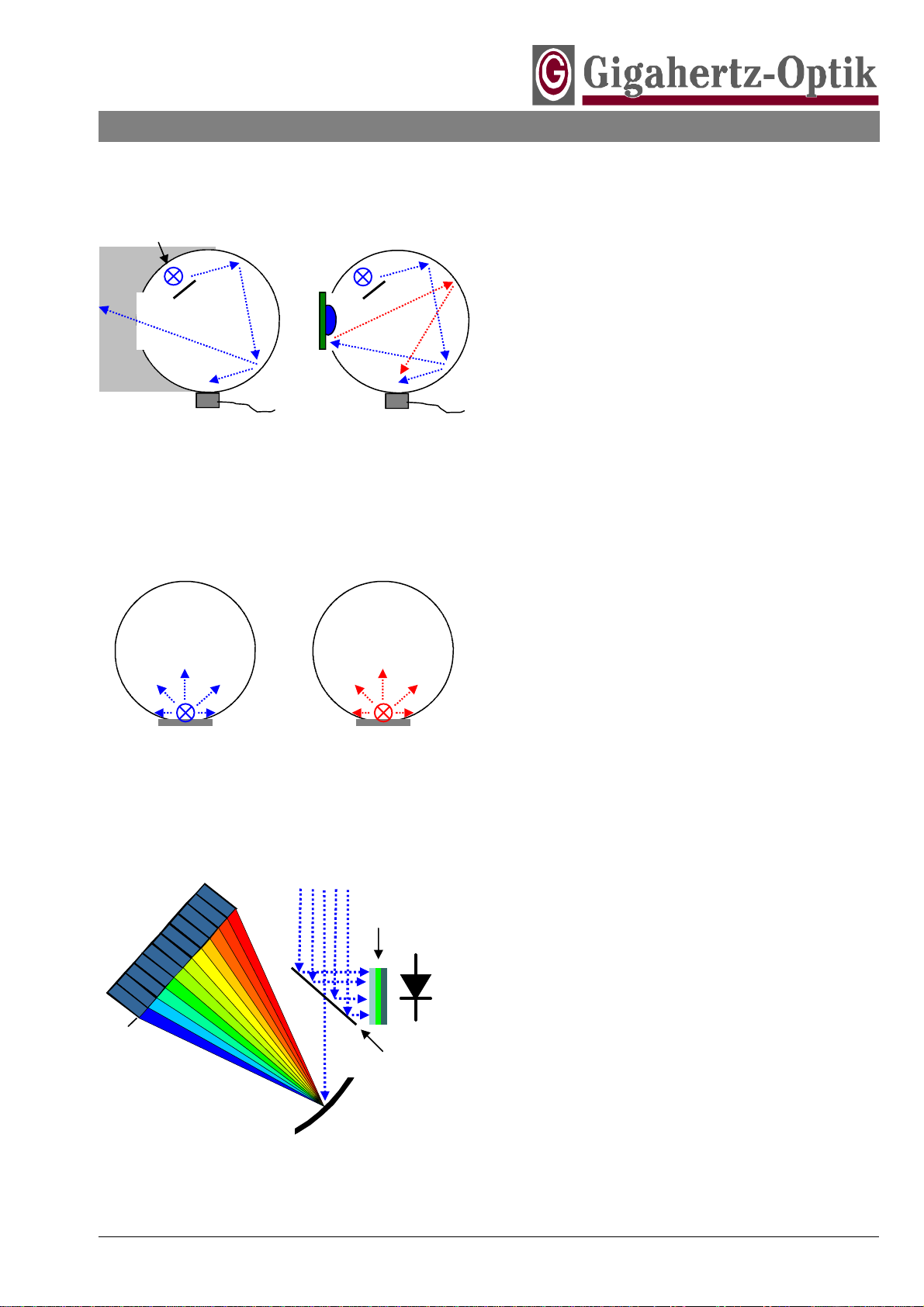
Measurementofluminousfluxwitha goniometricpho-
tometer isthe mostprecisemethodofmeasurement. Here
asummation ofthe spatialluminousintensitydistribution
withinthehemisphereinfrontoftheLEDisperformed.
Howeverthisisatimeand costintensivemethodtypically
applied inhigh levelR&Dand Qualitylaboratories.
Inindustryalight meterwithan integratingsphere (picture
6.3)arethemostcommon measurementdevicesem-
ployed.Thisapproachofferseasyand fastoperation as
wellascosteffectiveness.Theintegrating sphereactsas
lightintegratorforspatiallyemitting lightsources.The inte-
gration effectistheresultofmultiplediffusereflectionsof
the lighton the diffusereflecting surfaceofthehollow
spherewhichresultsinauniformlightdistribution atthe
spheresurface.Theilluminancemeasuredatanyposition
on theintegrating spheresurfaceisthereforean indicatorof
the totalfluxgenerated byalight sourceinside oroutside of
the sphere. Aswithanyothermeasurement deviceintegrat-
ing spheresexhibitsome typicalcharacteristics which
must beconsidered inuse:
1.The substitutioneffect isone sourceofmeasurement
uncertainty.During calibration ofthespherephotometer
someofthe lightirradiated intothe spherewillexitthe
Picture6.3:Integrating SpherePhotometer
Picture6.4:Substitution Effect
Picture6.2:LightMeasurementQuantities
LuminousFlux LuminousIntensity
[ lm]
I[ cd]
Light Detector
Baffle
Calibration: DarkRoom
withoutRe-reflected Light Measurement: DUTReflec-
ted Light backintoSphere