Marson MT82U Quick setup guide

MT82U 2D Scan Engine, Integration Guide, V0.1
M
MT
T8
82
2U
U
(
(2
2D
D
S
Sc
ca
an
n
E
En
ng
gi
in
ne
e)
)
I
In
nt
te
eg
gr
ra
at
ti
io
on
n
G
Gu
ui
id
de
e
Version 0.1 DATE: 2020/09/15

MT82U 2D Scan Engine, Integration Guide, V0.1
TABLE OF CONTENTS
1
1.
.
I
IN
NT
TR
RO
OD
DU
UC
CT
TI
IO
ON
N .........................................................................................1
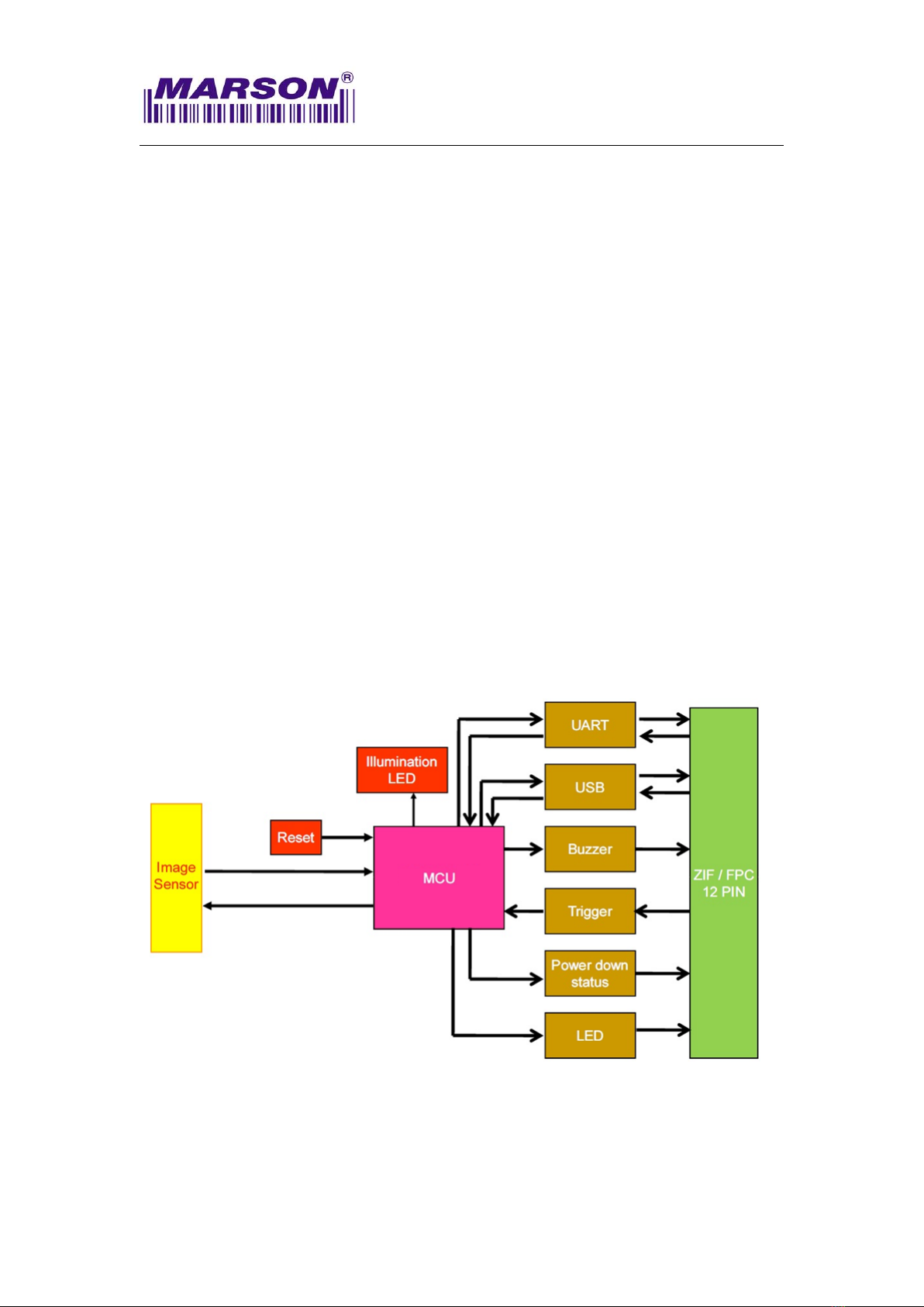
1-1. Block Diagram .................................................................................1
1
1-
-2
2.
.
E
El
le
ec
ct
tr
ri
ic
c
I
In
nt
te
er
rf
fa
ac
ce
e..............................................................................2
1
1-
-2
2-
-1
1.
.
P
Pi
in
n
A
As
ss
si
ig
gn
nm
me
en
nt
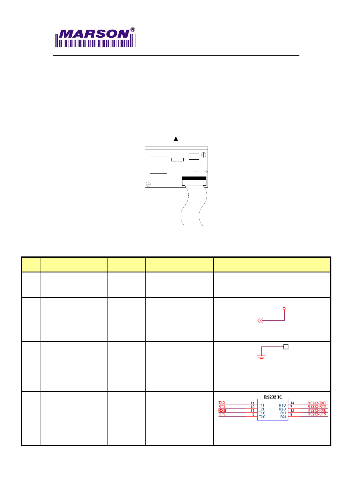
t .....................................................................2
1
1-
-2
2-
-2
2.
.
E
El
le
ec
ct
tr
ri
ic
c
C
Ch
ha
ar
ra
ac
ct
te
er
ri
is
st
ti
ic
cs
s ........................................................5
2
2.
.
S
SP
PE
EC
CI
IF
FI
IC
CA
AT
TI
IO
ON
NS
S .......................................................................................6
2
2-
-1
1.
.
I
In
nt
tr
ro
od
du
uc
ct
ti
io
on
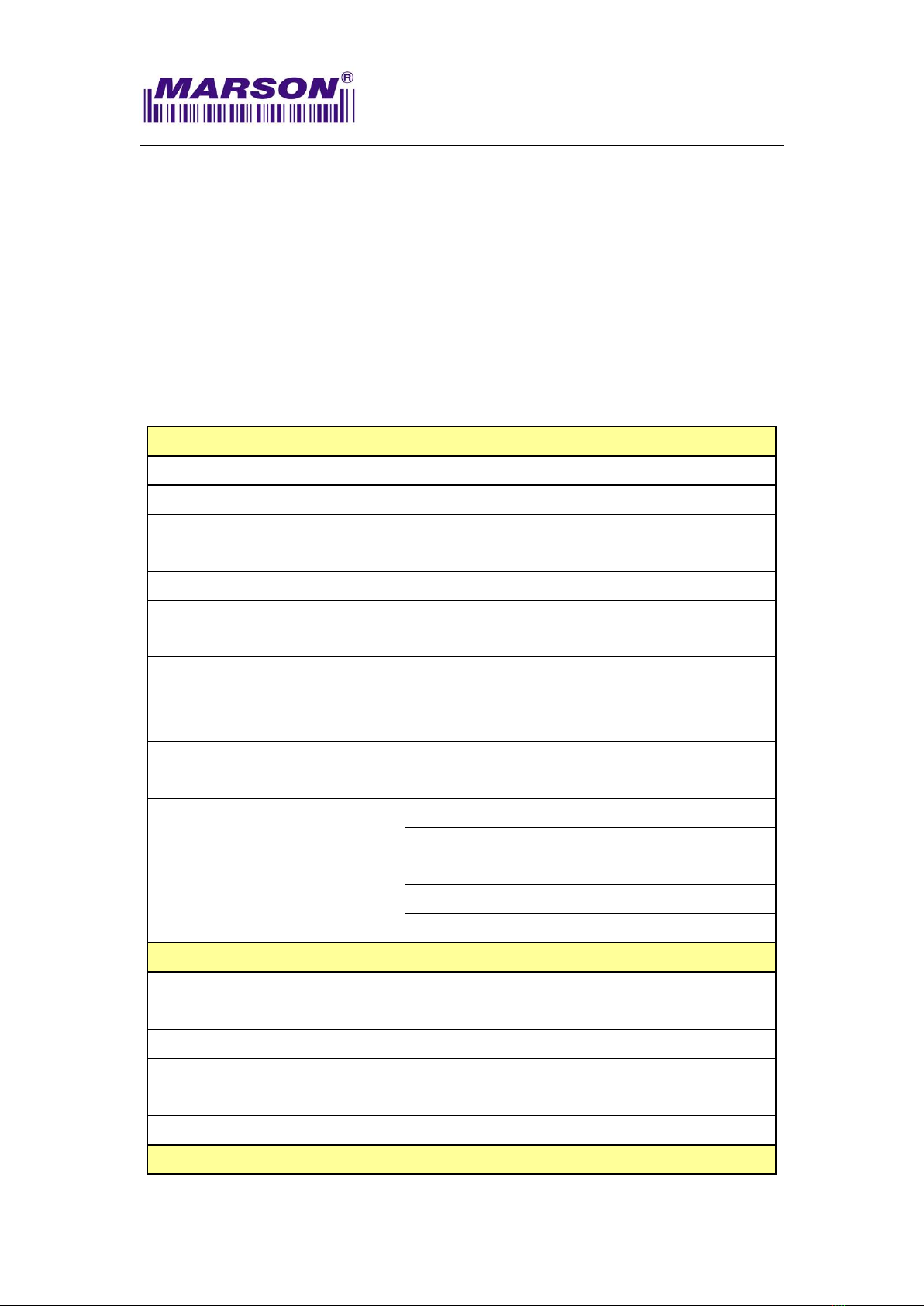
n......................................................................................6
2
2-
-2
2.
.
T
Te
ec
ch
hn
ni
ic
ca
al
l
S
Sp
pe
ec
ci
if
fi
ic
ca
at
ti
io
on
ns
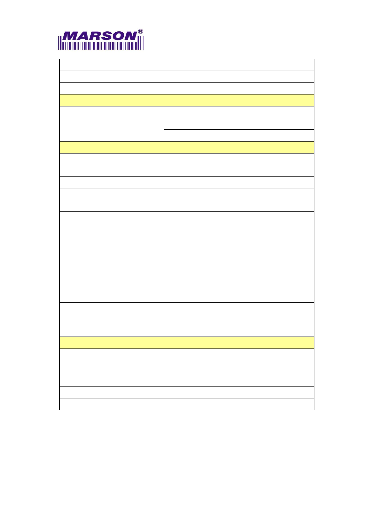
s .................................................................6
2
2-
-3
3.
.
I
In
nt
te
er
rf
fa
ac
ce
e............................................................................................8
2
2-
-3
3-
-1
1.
.
U
UA
AR
RT
T
I
In
nt
te
er
rf
fa
ac
ce
e ......................................................................8
2
2-
-3
3-
-2
2.
.
U
US
SB
B
H
HI
ID
D
I
In
nt
te
er
rf
fa
ac
ce
e..................................................................8
2
2-
-3
3-
-3
3.
.
U
US
SB
B
V
VC
CP
P
I
In
nt
te
er
rf
fa
ac
ce
e ................................................................8
2-4. Operation Method ............................................................................9
2
2-
-5
5.
.
M
Me
ec
ch
ha
an
ni
ic
ca
al
l
D
Di
im
me
en
ns
si
io
on
n ....................................................................9
2
2-
-6
6.
.
C
Co
on
nn
ne
ec
ct
to
or
r
S
Sp
pe
ec
ci
if
fi
ic
ca
at
ti
io
on
n .................................................................9
3
3.
.
I
IN
NS
ST
TA
AL
LL
LA
AT
TI
IO
ON
N ......................................................................................... 11
3
3-
-1
1.
.
E
El
le
ec
ct
tr
ro
os
st
ta
at
ti
ic
c
D
Di
is
sc
ch
ha
ar
rg
ge
e
C
Ca
au
ut
ti
io
on
ns
s................................................. 11
3
3-
-2
2.
.
M
Me
ec
ch
ha
an
ni
ic
ca
al
l
D
Di
im
me
en
ns
si
io
on
n .................................................................. 11
3-3. Window Materials ..........................................................................12
3
3-
-4
4.
.
W
Wi
in
nd
do
ow
w
S
Sp
pe
ec
ci
if
fi
ic
ca
at
ti
io
on
ns
s..................................................................13
3
3-
-5
5.
.
W
Wi
in
nd
do
ow
w
C
Ca
ar
re
e..................................................................................13
4
4.
.
R
RE
EG
GU
UL
LA
AT
TI
IO
ON
NS
S .........................................................................................14
5
5.
.
D
DE
EV
VE
EL
LO
OP
PM
ME
EN
NT
T
K
KI
IT
T.................................................................................15
6
6.
.
V
VE
ER
RS
SI
IO
ON
N
H
HI
IS
ST
TO
OR
RY
Y ..................................................................................16

MT82U Scan Engine, Integration Guide, V0.1
___________________________________________________________________________________
1
1
1.
.
I
IN
NT
TR
RO
OD
DU
UC
CT
TI
IO
ON
N
MT82U One-piece Compact 2D Scan Engine provides snappy scanning performance
at a competitive cost and compact form factor. With its all-in-one design, MT82U 2D
scan engine can be easily integrated with specific applications such as access control,
lottery kiosk and consumer electronics.
The MT82U 2D Scan Engine consists of 1 illumination LED, 1 aimer LED and a
high-quality image sensor with a microprocessor that contains powerful firmware to
control all aspects of operations and enable communication with the host system over
the standard set of communication interfaces.
Two interfaces, UART & USB, are available. UART interface communicates with the
host system over TTL-level RS232 communication; USB interface emulates a USB
HID Keyboard or Virtual COM port device and communicates with the host system
over USB.
1
1-
-1
1.
.
B
Bl
lo
oc
ck
k
D
Di
ia
ag
gr
ra
am
m

MT82U Scan Engine, Integration Guide, V0.1
___________________________________________________________________________________
2
1
1-
-2
2.
.
E
El
le
ec
ct
tr
ri
ic
c
I
In
nt
te
er
rf
fa
ac
ce
e
1
1-
-2
2-
-1
1.
.
P
Pi
in
n
A
As
ss
si
ig
gn
nm
me
en
nt
t
(Top View of MT82U)
Pin# UART USB I/O Description Schematic Example
1 NC NC ------------ Floating
2 VCC VCC ------------ Supply voltage input.
Must always be
connected to 3.3V
power supply.
+3V3
3 GND GND ------------ Power and signal
ground.
4 RXD RXD Input UART TTL data input.
Sipex®Vendor P/N: SP232ACT
Front
柔性线缆
1
12
1
12
5
mm

MT82U Scan Engine, Integration Guide, V0.1
___________________________________________________________________________________
3
Pin# UART USB I/O Description Schematic Example
5 TXD ------------ Output UART TTL data output.
Sipex®Vendor P/N: SP232ACT
6 ------------ USB_D- Bidirectional
USB Differential Signal
Transmission
(USB D-)
7 ------------ USB_D+ Bidirectional
USB Differential Signal
Transmission
(USB D+)
8 NC NC ------------ Floating
9 Buzzer
PWM
Buzzer
PWM
Output Active High: it
indicates the status of
Power-Up or a
successful barcode
decoded.
PWM controlled signal
can be used to drive
an external buzzer for
a successful barcode
decoded (Good Read).
USB_D+
USB_D-
GND
GND
VIN_
3
V
USB_Port
4
3
2
1
5
6
USB_D+
USB_D-
GND
GND
VIN_
3
V
USB_Port
4
3
2
1
5
6

MT82U Scan Engine, Integration Guide, V0.1
___________________________________________________________________________________
4
Pin# UART USB I/O Description Schematic Example
10 Good
Read
LED
Good
Read
LED
Output When scanning is
successful (Good
Read), it outputs a
high-level pulse,
whose load capacity is
limited and not enough
to driver LED directly.
A supporting LED drive
circuit is required.
11 Reset Reset Input Keeping low level for
at least 100us and
returning to high level
or floating state, the
scan engine restarts.
12 Trigger
Input
Trigger
Input
Input High: Stop Scanning
Low: Start Scanning
*Warning:
1. Pull low at power-up
will prompt the scan
engine into firmware
update mode.
Once trigger is pressed (pull lo
w), scanning
operation continues until a barcode is
successfully decoded or the trigger is released
(pull high). To proceed to the next scanning
operation, release (pull high) first and press (pull
low) the trigger again.
A minimum of 50ms
interval is reco
mmended between two trigger
signals.

MT82U Scan Engine, Integration Guide, V0.1
___________________________________________________________________________________
5
1
1-
-2
2-
-2
2.
.
E
El
le
ec
ct
tr
ri
ic
c
C
Ch
ha
ar
ra
ac
ct
te
er
ri
is
st
ti
ic
cs
s
Operating Voltage
Ta=25°C
Symbol
Ratings
Min
Typical
Max
Unit
VDD
Power supply 3.0 3.3 3.6
V
VIL
Input low level --- --- 0.8
VIH
Input high level 2 --- ---
VOL
Output low level --- --- 0.4
VOH
Output high level VDD-0.4 --- ---
Operating Current
Ta=25°C, VDD=3.3V
Ratings
Max
Unit
Standby Current 60 mA
Working Current
110

MT82U Scan Engine, Integration Guide, V0.1
___________________________________________________________________________________
6
2
2.
.
S
SP
PE
EC
CI
IF
FI
IC
CA
AT
TI
IO
ON
NS
S
2
2-
-1
1.
.
I
In
nt
tr
ro
od
du
uc
ct
ti
io
on
n
This chapter provides technical specifications of the MT82U. Operating method,
scanning range and scan angle are also presented.
2
2-
-2
2.
.
T
Te
ec
ch
hn
ni
ic
ca
al
l
S
Sp
pe
ec
ci
if
fi
ic
ca
at
ti
io
on
ns
s
Optic & Performance
Light Source white LED
Aiming visible red LED linear aimer
Sensor 640 x 480 pixels
Scan Rate 30 frames/ sec
Resolution 5mil/ 0.125mm (Code 39)
Field of View Horizontal 35°
Vertical 27°
Scan Angle
Pitch Angle ±55°
Skew Angle ±55°
Roll Angle 360°
Print Contrast Ratio 10%
Width of Field 156mm (13Mil Code39)
Typical
Depth Of Field
(Environment: 800 lux)
5 Mil Code39: 55 ~ 120mm
13 Mil UPC/EAN: 50 ~ 250mm
15 Mil QR Code: 30 ~ 180mm
6.67 Mil PDF417: 50 ~ 110mm
10 Mil Data Matrix: 25 ~ 170mm
Physical Characteristics
Dimension W21.5 x L14.5 x H10 mm
Weight 2.6g
Color Black
Material Plastic
Connector 12pin ZIF (pitch=0.5mm)
Cable 12pin flex cable (pitch=0.5mm)
Electrical

MT82U Scan Engine, Integration Guide, V0.1
___________________________________________________________________________________
7
Operation Voltage 3.3VDC ± 5%
Working Current < 110 mA
Standby Current < 60 mA
Connectivity
Interface
UART (TTL-level RS232)
USB (HID Keyboard)
USB (Virtual COM)
User Environment
Operating Temperature -20°C ~ 60°C
Storage Temperature -40°C ~ 80°C
Humidity 0% ~ 95%RH (Non-condensing)
Drop Durability 1.5M
Ambient Light 100,000 Lux (Sunlight)
1D Symbologies
UPC-A/ UPC-E
EAN-8/ EAN-13
Codabar
Matrix 2 of 5
Code 93
Code 128
Code 39
Interleaved 2 of 5
2D Symbologies
QR Code
PDF417
Data Matrix
Regulatory
ESD
Functional after 8KV contact, 12KV air discharge
(It requires housing that is designed for ESD
protection and stray from electric fields.)
EMC TBA
Safety Approval TBA
Environmental WEEE, RoHS 2.0

MT82U Scan Engine, Integration Guide, V0.1
___________________________________________________________________________________
8
2
2-
-3
3.
.
I
In
nt
te
er
rf
fa
ac
ce
e
2
2-
-3
3-
-1
1.
.
U
UA
AR
RT
T
I
In
nt
te
er
rf
fa
ac
ce
e
Below are default communication protocols:
Baud rate: 9600
Data Bits: 8
Parity: None
Stop Bit: 1
Handshaking: None
Flow Control Timeout: None
ACK/NAK: OFF
BCC: OFF
Interface Configuration Barcode:
UART
2
2-
-3
3-
-2
2.
.
U
US
SB
B
H
HI
ID
D
I
In
nt
te
er
rf
fa
ac
ce
e
Interface Configuration Barcode:
USB HID
2
2-
-3
3-
-3
3.
.
U
US
SB
B
V
VC
CP
P
I
In
nt
te
er
rf
fa
ac
ce
e
Interface Configuration Barcode:
USB VCP

MT82U Scan Engine, Integration Guide, V0.1
___________________________________________________________________________________
9
2
2-
-4
4.
.
O
Op
pe
er
ra
at
ti
io
on
n
M
Me
et
th
ho
od
d
1. At power-up, the MT82U sends the Power-Up signals over Buzzer and LED
pins as an indication that the MT82U enters Standby Mode and is ready for
operation.
2. Once the MT82U triggered by either hardware or software method, MT82U
will emit a beam of light which is aligned with the sensor’s field of view.
3. The area image sensor captures the image of barcode and produces an
analog waveform, which is sampled and analyzed by the decoder firmware
running on the MT82U.
4. Upon a successful barcode decoded, the MT82U turns off the illumination
LEDs, sending the Good Read signals over Buzzer and LED pins and
transmitting the decoded data to the host.
2
2-
-5
5.
.
M
Me
ec
ch
ha
an
ni
ic
ca
al
l
D
Di
im
me
en
ns
si
io
on
n
(Unit = mm)
Front view Bottom view
21
.5mm
17
.3mm
10
.
7
mm
Depth 2.4mm MAX
14
.
Front
2.1mm
1
.9mm
1
4.5mm
Ф
1mm*2

MT82U Scan Engine, Integration Guide, V0.1
___________________________________________________________________________________
10
2
2-
-6
6.
.
C
Co
on
nn
ne
ec
ct
to
or
r
S
Sp
pe
ec
ci
if
fi
ic
ca
at
ti
io
on
n
Below is the recommended 12-pin 0.5-pitch FPC connector on the host side.

MT82U Scan Engine, Integration Guide, V0.1
___________________________________________________________________________________
11
3
3.
.
I
IN
NS
ST
TA
AL
LL
LA
AT
TI
IO
ON
N
The scan engine is designed specifically for integration into customer's housing for
OEM applications. However, the scan engine’s performance will be adversely affected
or permanently damaged when mounted into an unsuitable enclosure.
Warning: The limited warranty is void if the following recommendations are not
adhered to when mounting the scan engine.
3
3-
-1
1.
.
E
El
le
ec
ct
tr
ro
os
st
ta
at
ti
ic
c
D
Di
is
sc
ch
ha
ar
rg
ge
e
C
Ca
au
ut
ti
io
on
ns
s
All scan engines are shipped in ESD protective packaging due to the sensitive
nature of the exposed electrical components.
1. ALWAYS use grounding wrist straps and a grounded work area when
unpacking and handling the scan engine.
2. Mount the scan engine in a housing that is designed for ESD protection and
stray electric fields.
3
3-
-2
2.
.
M
Me
ec
ch
ha
an
ni
ic
ca
al
l
D
Di
im
me
en
ns
si
io
on
n
When securing the scan engine by utilizing the machine screws:
1. Leave sufficient space to accommodate the maximum size of the scan engine.
2. Do not exceed 1kg-cm (0.86 lb-in) of torque when securing the scan engine to
the host.
3. Use safe ESD practices when handling and mounting the scan engine.

MT82U Scan Engine, Integration Guide, V0.1
___________________________________________________________________________________
12
3
3-
-3
3.
.
W
Wi
in
nd
do
ow
w
M
Ma
at
te
er
ri
ia
al
ls
s
Following are descriptions of three popular window materials:
1. Poly-methyl Methacrylic (PMMA)
2. Allyl Diglycol Carbonate (ADC)
3. Chemically tempered float glass
Cell Cast Acrylic (ASTM: PMMA)
Cell cast Acrylic, or Poly-methyl Methacrylic is fabricated by casting acrylic
between two precision sheet of glass. This material has very good optical quality,
but is relatively soft and susceptible to attack by chemicals, mechanical stress
and UV light. It is strongly recommended to have acrylic hard-coated with
Polysiloxane to provide abrasion resistance and protection from environmental
factors. Acrylic can be laser-cut into odd shapes and ultrasonically welded.
Cell Cast ADC, Allyl Diglycol Carbonate (ASTM: ADC)
Also known as CR-39TM, ADC, a thermal setting plastic widely used for plastic
eyeglasses, has excellent chemical and environmental resistance. It also has an
inherently moderate surface hardness and therefore does not require
hard-coating. This material cannot be ultrasonically welded.
Chemically Tempered Float Glass
Glass is a hard material which provides excellent scratch and abrasion
resistance. However, un-annealed glass is brittle. Increased flexibility strength
with minimal optical distortion requires chemical tempering. Glass cannot be
ultrasonically welded and is difficult to cut into odd shapes.
Property Description
Spectral Transmission 85% minimum from 635 to 690 nanometers
Thickness < 1 mm
Coating
Both sides to be anti-reflection coated to provide 1%
maximum reflectivity from 635 to 690 nanometers at
nominal window tilt angle. An anti-reflection coating can
reduce the light that is reflected back to the host case.
Coatings will comply with the hardness adherence
requirements of MIL-M-13508.

MT82U Scan Engine, Integration Guide, V0.1
___________________________________________________________________________________
13
3
3-
-4
4.
.
W
Wi
in
nd
do
ow
w
P
Pl
la
ac
ce
em
me
en
nt
t
L
The distance between window and front of MT82U should not exceed L=0.5mm
The thickness of the window should not exceed 1mm
3
3-
-5
5.
.
W
Wi
in
nd
do
ow
w
S
Si
iz
ze
e
The window size should ensure that field of view is not blocked, and the illumination
area should not be blocked as well. For the size of window, please refer to above
diagram of each optical area.
3
3-
-6
6.
.
W
Wi
in
nd
do
ow
w
C
Ca
ar
re
e
In the aspect of window, the performance of MT82U will be reduced due to any kind of
scratch. Thus, reducing the damage of window, there are few things have to be
noticed.
1. Avoid touching the window as much as possible.
2. When cleaning the window surface, please use non-abrasive cleaning cloth, and
then gently wipe the host window with the cloth that is already sprayed with glass
cleaner.
V
ertical illumination area
Vertical field of view
12
mm
A
imer 28°
H
orizontal field of view
Horizontal
i
llumination area
MT82U Side View

MT82U Scan Engine, Integration Guide, V0.1
___________________________________________________________________________________
14
4
4.
.
R
RE
EG
GU
UL
LA
AT
TI
IO
ON
NS
S
The MT82U scan engine conforms to the following regulations:
1. Electromagnetic Compliance – TBA
2. Electromagnetic Interference – TBA
3. Photobiological Safety – TBA
4. Environmental Regulations – RoHS 2.0, WEEE

MT82U Scan Engine, Integration Guide, V0.1
___________________________________________________________________________________
15
5
5.
.
D
DE
EV
VE
EL
LO
OP
PM
ME
EN
NT
T
K
KI
IT
T
TBA

MT82U Scan Engine, Integration Guide, V0.1
___________________________________________________________________________________
16
6
6.
.
V
VE
ER
RS
SI
IO
ON
N
H
HI
IS
ST
TO
OR
RY
Y
Rev.
Date
Description
Issued
Checked
0.1 2020.09.15 Preliminary Draft Release Shaw Kenji
Marson Technology Co., Ltd.
9F., 108-3, Mincyuan Rd., Sindian Dist., New Taipei City, Taiwan
TEL: 886-2-2218-1633
FAX: 886-2-2218-6638
E-mail: [email protected]
Web: www.marsontech.com
Table of contents
Popular Test Equipment manuals by other brands

ASSOCIATED EQUIPMENT CORPORATION
ASSOCIATED EQUIPMENT CORPORATION 6034 Operator's manual

APS
APS 3C Series Operation manual

ZETRON
ZETRON Viavi 3550 Maintenance Guide

Maco
Maco TRONIC 480525 operating instructions

RICE HYDRO
RICE HYDRO TR Series operating instructions

Hantek
Hantek Tablet1000 Series user manual

Kurth
Kurth KE301 manual

Hioki
Hioki 3417 instruction manual

METREL
METREL OmegaPAT XA MI 3360 instruction manual

Testboy
Testboy 40 Plus operating instructions

Berkeley Varitronics Systems
Berkeley Varitronics Systems Gazelle user manual

Valhalla Scientific
Valhalla Scientific Alpha 4314 Series Operation manual