GIGAMEDIA GGM IPAMIC User manual

IP NETWORK TALKBACK
TERMINAL
GGM IPAMIC
User Manual
Before using the system, please read this manual first

- 2 -
Important Instruction
warning
To ensure the safety and reliability of equipment and personnel during the process of installation,
use and maintenance, please observe the following items:
● If you find out any of the following unusual situation during the using process, please
immediately turn off power, plug out and quickly contact your nearest dealer. Do not use the
machine, because it may cause a fire or electric shock.
● If you detect smoke or a strange smell from the unit.
● If water or any metal object falls into this unit.
● If this machine has been dropped or the cabinet is damaged.
● Such as wire breakage (exposed core wire, broken, etc.).
● Containing high-voltage parts inside of the machine, to avoid fire or electric shock, please never
open the cabinet of the unit, any questions please inform your nearest dealer.
● Do not place cups, bowls, vases or metal is filled with water and other materials placed on this
unit. If accidentally something liquid is split into the unit, it may cause a fire or electric shock.
● The machine must not be exposed to rain and water at any damp or easily, it may cause electric
shock or fire.
● Not place metal objects or flammable materials from the vent cover on the machine, and do not
put coins which may result in a fire or electric shock flowers.
● Do not place heavy objects on the machine, in order to avoid personal injury or property damage
caused by the unit falling.
● To ensure that pre-boot volume to the minimum, turn the volume too high may cause hearing
problems.
● Do not use the machine at the sound distortion, which means that a fault may cause heat and
fire inside the machine.
● Due to long-term accumulation of dust to be cleaned, please notify your dealer regular to clean
machines, in order to avoid damage of the machine even cause a fire.
● As a Class I device, it must be well connected to the socket with grounded plug device, and the
plug must be connected to a grounded power outlet in order to ensure adequate grounding device.
● For this equipment, if the mains plug and appliance couplers are regarded as the disconnect
device, indicating that the disconnect device shall remain easy to operate.
● Due to the continuous updating of appearance and function, please kindly see the models based
on the entity, And the final interpretation of the product specification belongs to company.

- 3 -
Contents
Foreword...................................................................................................................................................... 4
1. Product Introduction.............................................................................................................................. 5
2. Features...................................................................................................................................................5
3. Nomenclature and Functions...............................................................................................................6
4. System Connection Diagram............................................................................................................... 7
5. Operating Instruction............................................................................................................................. 7
6. The principle block diagram............................................................................................................... 10
7. Performance Technical Parameters..................................................................................................11
8. Common Fault Handling.....................................................................................................................12

- 4 -
Foreword
《IP network talkback terminal product user manual》mainly introduces the GGM IPAMIC IP
network talkback terminal operation method, and the main performance parameters, common fault
solution.
This manual is only as the user operation instructions, not for maintenance purposes.Since the
issue date, if the function or related parameters changed, will be supplementary instruction, can
enquire from the dealer in details.
This manual is the company all rights reserved, without permission, any organization or individual
shall not make part or all of its contents of this manual for commercial purposes.
This manual copyright is subject to the law of the《People's Republic of China copyright law》and
other intellectual property laws and regulations to protect.Without the written permission shall not
copy or distribute.

- 5 -
1. Product Introduction
It suitable for all kinds of call center, alarm center, duty room, leader office, conference room, etc, it
can be variety of terminals of network in intercom calling(one-way to point, the partition or all zone,
two-way intercom or monitor.
2. Features
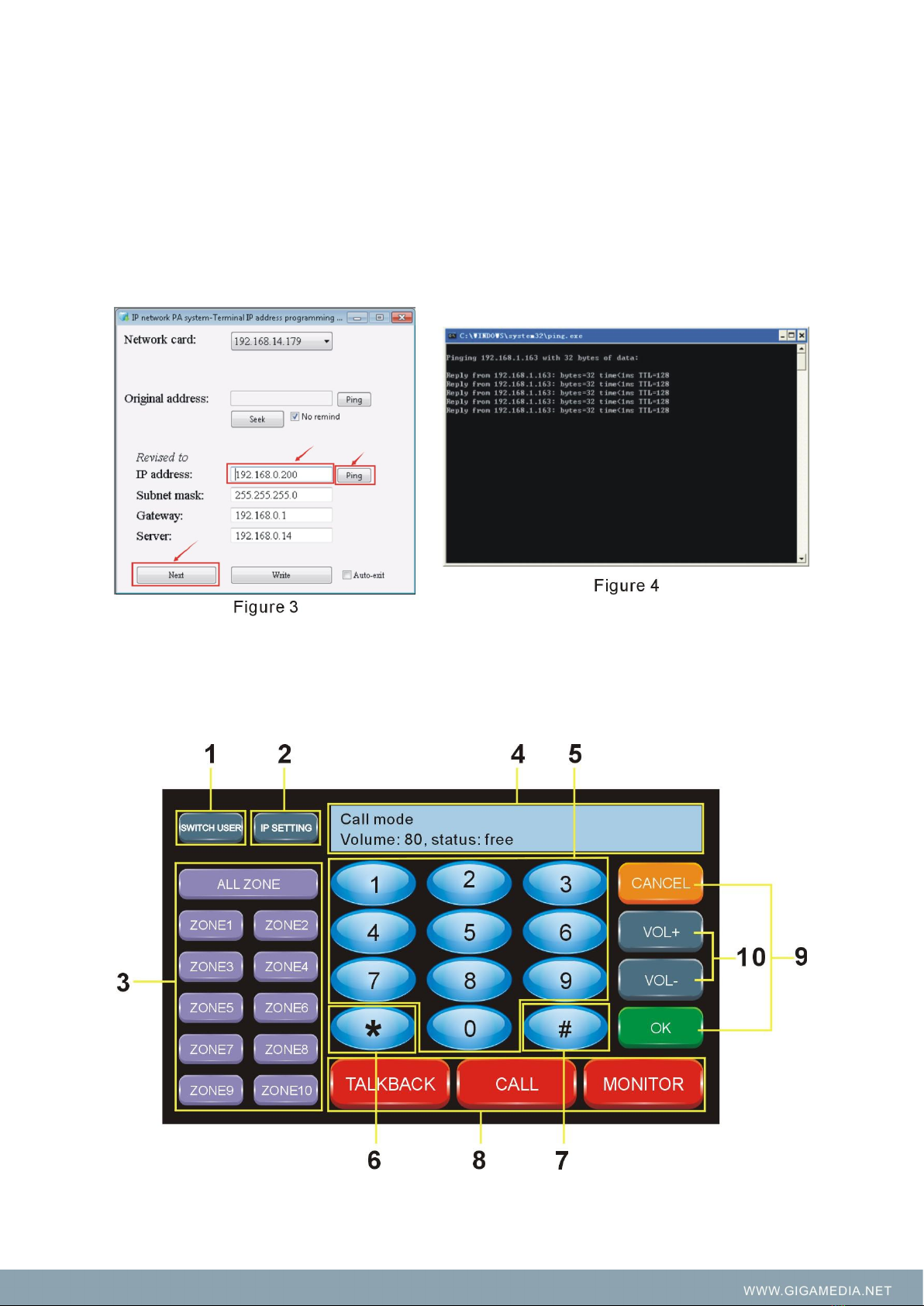
1. It built-in 7" 800*480 graph dot matrix, K600 + core 65k color touch screen display of resistance.
clear display, touch sensitive. No operation is entered into a state of dormancy, low-power save
electricity. Humanized human-computer interface.
2. It built-in numeric keys, function key interface.Support one key call partition, one key call all
zones broadcast; Support direct operation call or any terminal intercom; Support direct operation
to monitor (environmental monitoring) any terminal according to the practical environment,
monitoring distance of 5 meters. simple, intuitionistic and fast.
3. Support DHCP, compatible routers, switcher, network bridges, gateways, Modem, Internet, 2G,
3G, 4G, multicast, unicast and other arbitrary network structure.
4. Support full-duplex two-way intercom function, built-in network echo cancellation module.
Between IP terminal achieve two-way intercom, network delay is less than 300ms. Meanwhile
network echo howling suppression completely.
5. Support help ringing signal, splash screen prompt, one key to receive help, intercom function, it
can also support hands-free calls and receive broadcast, realize fast links.
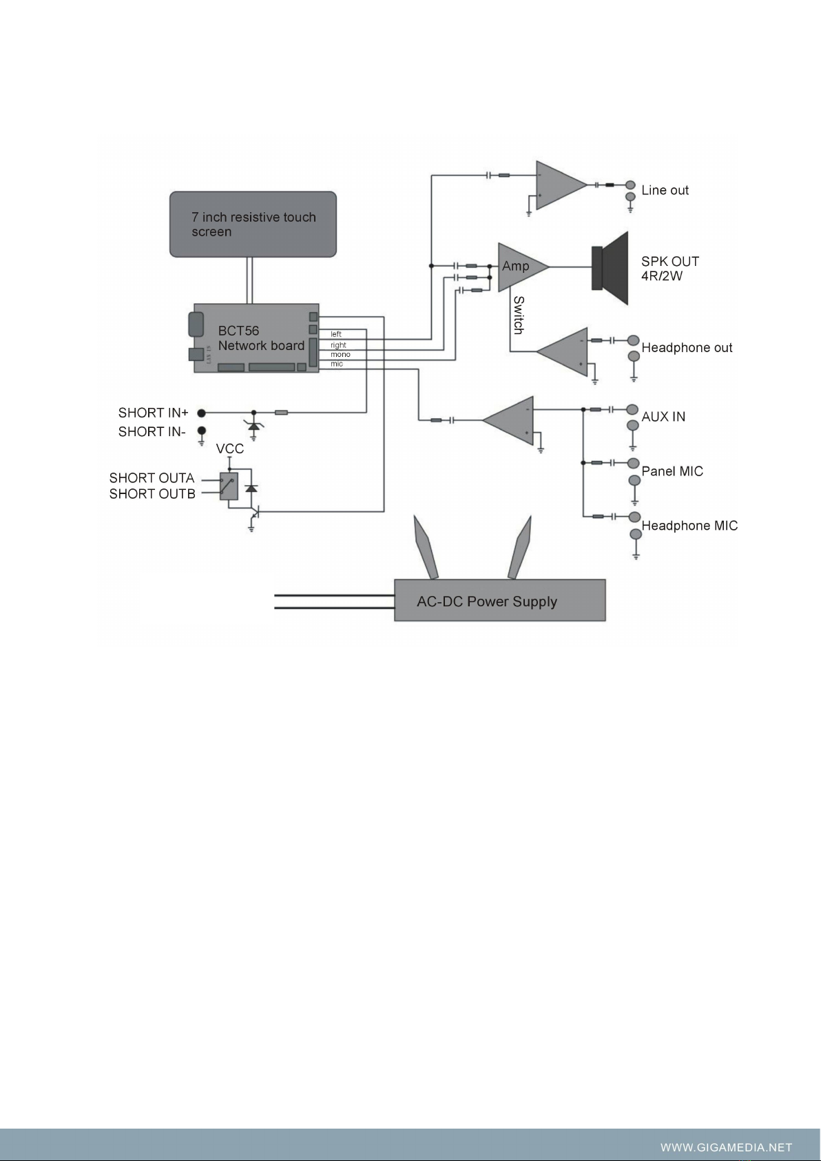
6. Built-in 2W full frequency monitoring speaker, the sound is clear and loud.
7. One φ3.5 headphone socket and one φ3.5 MIC input socket, matching the market 95% of
headsets and portable MIC.
8. One way audio line output, the expansion of power amplifier; one way audio line input, provide
multi-audio source transmission.
9. One way alarm trigger short circuit output, cascade extended warning device; one way
short-circuit input can be used as trigger preset voice prompts (or alarm).
10. DC 24V power supply interface, external connect with adapter.

- 6 -
3. Components and Functions
● Paging console: Microphone input.
● Built-in monitor speaker: to monitor the voice in the intercom environment.
● Display screen: LCD display screen, to display the working state and function operation.
● Standby interface: no special function.
● LAN network interface: RJ45 communication interface for networking of PC controller / Ethernet
/ switcher.
● 3.5mm external microphone connection interface: this 3.5mm microphone will be priority after
inserted.
● Headphone input interface: after inserting the headphone, the monitor speaker will not display
the intercom voice when paging.
● Short circuit input/output interface: short circuit input is used for receiving short circuit signal and
can be connected with door clock state inspection or entering prompt tone state inspection.
● Line input/output interface: line input is used for connecting audio devices, like CD. Line output is
used for cascading another device.
● Power switch: press down for power on, and press up for power off.
● Power input interface: input DC 24V power.
Build-in Monitor Speaker
LCD Screen
Microphone
Standby
interface
LAN
Interface
3.5mm MIC Input
Earphone Input
Line IN/OUT
Short-Circuit IN/OUT
Line IN/OUT
Power On/Off
Power IN

- 7 -
4. Connection Diagram of the System
5. Operation Instructions
Terminal Configuration
Connect with the LAN IN interface and the network interface or switcher with the network cable.
Open the file “IP software” in PC and select to run the procedure “Run the server”. Then, select to
run the procedure “configure IP address”. Single click the button “Query” (figure 1) on the pop-up
interface can check the IP address of the terminal (figure 2). As shown blow:

- 8 -
If it is necessary to amend the IP address of the terminal according to the requirement of system
configuration, then you can amend the “IP address” in the dialogue window or press “next” button
(on the basis of existing IP address +1 ascending order ) As shown blow figure 3, after setting the
corresponding parameters, click “edit” to edit, press “PING” button, check if the new IP address
terminal connect with the server, the pop-up window (As shown blow figure 3), shows that the
terminal which modify the new IP address has connected with server, then you can close the
window: “configure IP address”.
Introduction for Screen and Buttons
The standby screen show as below after start-up:

- 9 -
①Login: When the server is succeed to connect with the terminal, it will show” Connected”, When
the server is out off connection with the terminal, it will show: “not connected”
②IP setting: It is mainly used for look up terminal information, such as terminal IP address, subnet
mask, gateway and the server address, if you need configure the terminal IP, please configure on
the PC software on the server.
③Partition public address button: Please set the corresponding group in the IP software before
operating this button (The machine support 10 group only), then enter into “shortcut key” to fill the
corresponding group on the terminal configuration, restart the IP software. Then you will see the
corresponding group name. Press the group button, then press “#” button, then OK button to
speak to zones or all zones.
④Status: When it is free, it will show the wake-mode, the volume of terminal and the working
status (according to terminal configuration). When the machine operate other functions, it will
show the content correspondingly.
⑤0-9 number button: It is mainly used with other function keys, such as modifying the address,
calling a terminal, monitoring a terminal and so on.
⑥“*” button: under the coding status, press this button to return cancel.
⑦“#” button: This is a additional button when public address, for example, input the terminal code
then press this button to add more terminals. ( maximum 4 )
⑧“TALKBACK” button, “CALL” one way call button and “MONITOR” monitor button: There are
two operating ways to realize this function, press CALL+ NUMBER button + OK or NUMBER
button+CALL.
⑨“CANCEL” cancel button and “OK” confirm button: This is to confirm or hand off button when
intercom, broadcast or monitor.
⑩Volume UP/Down button: when intercom and one way calling or play background music, press
this button to up/down the volume.

- 10 -
6. Devices diagram
Power input

- 11 -
7. Technical Parameters
Model
GGM IPAMIC
Network interface
Standard RJ45 input
Support protocol
TCP/IP, UDP, IGMP Multicast
Audio format
MP3/MP2
Sampling frequency
8K~48KHz
Transmission rate
100Mbps
Audio modes
16 bit stereo with CD sound quality
Display screen size
7 inch
Screen resolution
800*480 pixel
Screen type
65K color DGUS screen
Keyboard type
Virtue QWERTY keyboard
Keyboard input way
Touch-control
Built-in impedance and power rating
4Ω, 2W
Total harmonic distortion
THD≤1%
Frequency response
80Hz~16KHz, +1dB/-3dB
SNR
>68dB
PHONE OUT output impedance and power rating
32Ω, 20mW
LINE OUT output voltage
1000mV industry standard line terminal
LINE OUT output impedance
470Ω
LINE IN input Sensitivity
350mV industry standard line terminal
MIC input sensitivity (unbalance)
10mV
Short circuit input
Dry contact input
Short circuit output
Max 3A/120V dry contact
Working temperature
5℃~40℃
Working Humidity
20%~80% relative humidity without condensing
Total power loss
≤8W
Standard DC input
DC 24V
Normal working voltage
DC12~24.5V
Dimension
200*160*60 mm
Net Weight
0.82kg

- 12 -
8. Troubleshooting Dealing Methods
Why cannot call out or paging through other terminals?
The reason is that the called or intercom terminal is receiving a higher priority task. Need to
operate after the other side end to finish the task or contact your administrator to improve the task
priority.
Why cannot perform the timed task programmed?
The cause is the start date and end date of the task set incorrectly. It can focus your attention on
the task start date and end dates settings. In addition, check if this task is started up. Finally to
confirm the performance date is according to the server, not the terminal computer.
Why user cannot log in?
The cause is the wrong server address, user name and wrong passwords. Please confirm the
information and log in again.
Why user cannot operate some terminals?
This is because administrator did not distribute the management rights for this user.
Why the task performance is disordered?
Check the priority grade of the task setting is right or not. The tasks at the same time will be
performed as below principles: later task will be priority at the same task grade, higher position
user’s task will be priority, and higher priory grade terminal will be priority.
If the problem is still not solved, please contact with our service department.

IP Network Talk back Terminal
VersionV0.1
Table of contents
Other GIGAMEDIA Microphone manuals