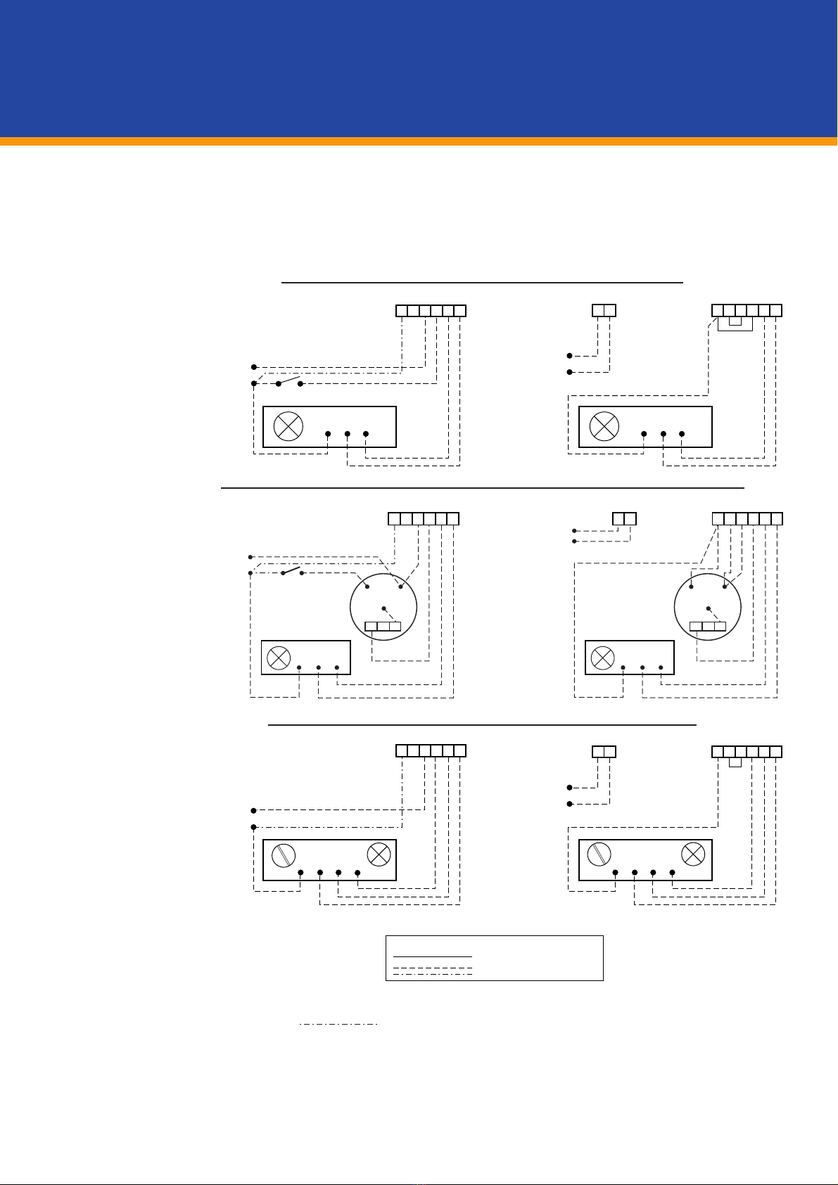
GILBERTS DUCTGARD User manual

UDC 697.9
SFB (57.9) X
Features
- Stainless Steel interlocking blades and frame side seals
- Unique patented precision blade linkage mechanism
- 8 Different modes of operation
- Connections to suit most proprietary duct work
- Extensive range of external control facilities
DUCTGARD
Duct Mounting Smoke
and Fire Control Dampers
Dampers 1 NOV 2012

Gilberts Ductgard presents an
‘engineered’ range of combined
smoke and fire dampers
suitable for use in all types of
HVAC ductwork.
Developed from our well
proven door mounting
smokegard damper, over
40 years of engineering
experience in the industry and
considerable ingenuity has
been applied in the design and
construction of this product to
produce a damper of high
efficiency, reliability, durability
and ease of use.
INTRODUCTION

The Gilbert’s 2007 Ductgard
presents a re-engineered range of
combined fire and smoke dampers
suitable for use in HVAC ductwork
systems.
Developed from a well proven,
tried and tested damper,
considerable ingenuity and
manufacturing expertise has been
further applied to produce a robust,
effective, competitive unit that is
easy to install and maintain.
The unit is designed to fit within all
types of ductwork at its juction with
a fire barrier wall, where it can be
fixed directly in or immediately
adjacent to the building structure
in both the horizontal and vertical
positions.
A choice of 8 different modes of
operation are available providing
for both a manual and fully
automatic operation.
All units comprise of an air-tight
galvanised casing (DW144 Class
C Specification) with stainless steel
interlocking blades and frame side
seals, which provides a four-hour
fire rated assembly. Sizes range
from 200 x 200 upto a maximum
of 1000 x 1000 in one unit.
Dampers over this size are supplied
in multiple units. Intermediary sizes
are available as standard upon
request.
Mode Description Page
5A Fully automatic electronic 24v DC opening with fail safe spring 4
closure via 72°C electro thermal link release
5B Fully automatic electronic 240v AC opening with fail safe spring 4
closure via 72°C electro thermal link release
6A Fully automatic electronic 24v DC closure with fail safe spring 4
opening via 72°C electro thermal link release
6B Fully automatic electronic 240v AC closure with fail safe spring 4
opening via 72°C electro thermal link release
9A Fully automatic motorised 24v AC/DC opening and fail safe 5
spring closure via 72°C electro thermal link release
9B Fully automatic motorised 240v AC opening and fail safe spring 5
closure via 72°C electro thermal link release
10A Fully automatic motorised 24v AC/DC closure and fail safe 5
spring opening via 72°C electro thermal link release
10B Fully automatic motorised 240v AC closure and fail safe 5
spring opening via 72°C electro thermal link release
Control Mode Options
ANCILLARY FEATURE OPTIONS
-REMOTE CONTROL PANELS - HARD WIRED & MULTIPLEX
-REMOTE STATUS INDICATION AND TEST PANELS
-VOLT FREE CONTACTS FOR REMOTE ELECTRICAL/BLADE STATUS INDICATION
-HEVAC BUILD IN AND DRY WALL FIXING FRAMES
- ACCESS PANELS

Features
Inter-Connecting
Mechanism
All Ductgard units are
driven using a unique,
patented, interconnecting
rack mechanism as
illustrated. This
intrinsically simple
mechanism has been
ingenuitively applied to
the damper and its
characteristics ensure that
all units can operate
repeatedly with faultless
precision. Added benefits
include reliability,
durability, speed and low
torque operating
conditions.
Interlocking Blade
Operation
The Stainless Steel
Blades featured on the
Ductgard units,
incorporate a fishtail edge
detail which, with the help
of the precision single
rack operation, enables
the blades to close and
interlock extremely tightly.
This provides a tough,
effective screen against
smoke and flames for its
maximum 4 hour rating.
Stainless Steel
Edge Seals
These provide effective
barriers to cold smoke
penetration and allow the
blades to expand under
fire conditions minimising
leakage at all times
1.2mm welded duct to damper
extension fitted as standard to
house control options, offers
DW142 Class C specification.
Connections to suit most
proprietary ductwork flanges
and spigots.
8 different modes of
operation
3
DUCTGARD
Duct Mounting Smoke and Fire Control Dampers

Mode 5
Mode 6
OPTIONAL FEATURES
-A RANGE OF MULTIPLEX OR ELECTRO-MECHANICAL CONTROL
PANELS
-REMOTE, ELECTRICAL BLADE STATUS INDICATION PANELS
-HEVAC INSTALLATION FRAME/DRY WALL FIXING FRAME
-ACCESS PANEL
Description
Mode 5 is a fully automatic type of smoke and
fire damper and operates on the basis of fail
safe closure with automatic reset. It has been
designed to close in smoke and fire conditions
upon signal from a fire detection system or in
the event of an electro thermal fusible link
separating at a pre-determined temperature
(72°C standard).
Operation
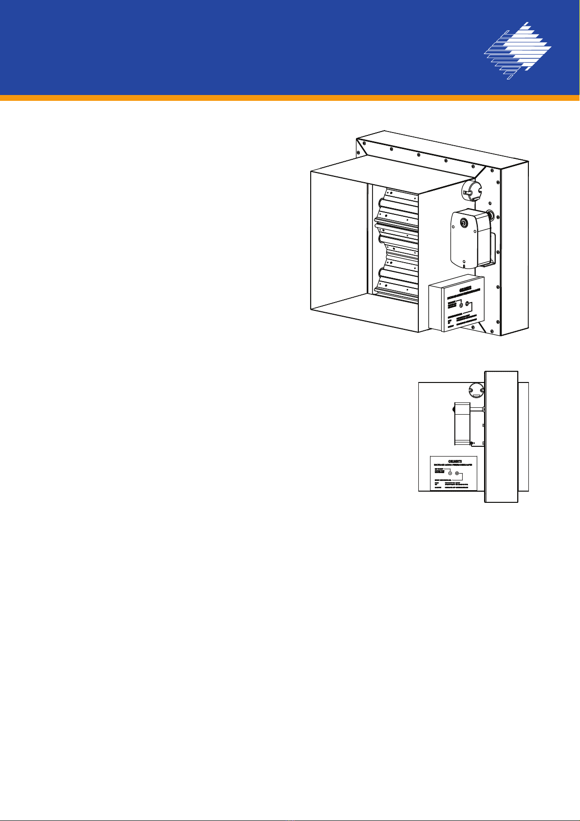
Mode 5 is fitted with a square drive spring return
motor which will hold the damper open for as
long as the supply voltage is available.
Interruption of this supply will cause controlled
damper closure by way of the motors spring
return operation. In addition however, the
damper is also fitted with an electro thermal
fusible link which will separate at a pre-
determined temperature (72°C standard) and
close the damper irrespective of motor position.
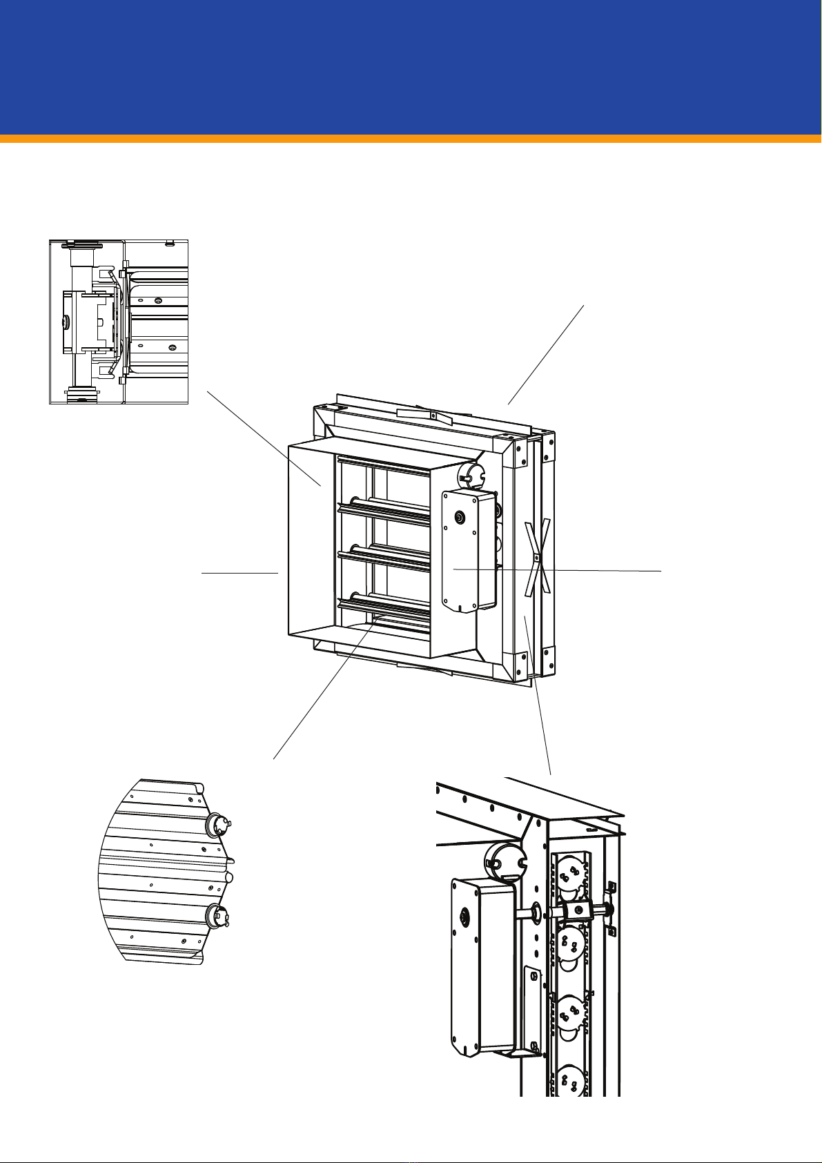
All Mode 5 units are also fitted with a control
box which is situated on the dampers ductwork
extension and houses the integral PCB, status
indication L.E.D. and test facility. The test key
facility allows local checks to be made on the
damper operation.
The L.E.D., provides the following diagnostic
checks:-
GREEN DISPLAY:- Power supply ON, unit set.
RED DISPLAY:- Power supply ON, but unit in
fail safe mode.
NO DISPLAY:- Power supply failure, unit in fail
safe mode.
The control box also provides an interface for
remote status indication, smoke detectors and
RCP control (see page 11 and 12).
Control Options
A- 24v DC Power Supply
B- 240v AC Power Supply
Re-Set Procedure
Provided the fusible link is intact and the remote
or local test facility is not being utilised the
damper will automatically reset after an
interruption of the supply voltage. The motor will
take approximately 80 seconds to fully open the
damper.
The LED indicator and test facility are housed in
a control panel mounted on the ductwork
connection sleeve. Fully assembled prior to
despatch they require only the external electrical
wiring connections to be made on site.
Mode 6 performs in exactly the same manner as
the Mode 5 except that the operation is reversed
and the unit is fail safe open. The motor sets the
unit in the closed position and the unit will only
open in the event of a signal from the fire
detection system, separation of the thermal
fusible link or operation of the key test facility.
Ordering procedure: Back cover.
4

Mode 9
Mode 10 OPTIONAL FEATURES
-A RANGE OF ELECTRO-MECHANICAL CONTROL PANELS
-VOLT FREE CONTACTS FOR REMOTE INTERFACE
-REMOTE, ELECTRICAL BLADE STATUS INDICATION PANELS
-DAMPER MOUNTING TERMINAL BOX FOR MICROSWITCH
AND/OR MOTOR CABLING
-HEVAC INSTALLATION FRAME/DRY WALL FIXING FRAME
-ACCESS PANELS
Description
Mode 9 is a fully automatic type of smoke and
fire damper and operates on the basis of fail
safe closure with automatic reset. It has been
designed to close in smoke and fire conditions
upon a failure of the supply voltage to the motor
or in the event of an electro thermal fusible link
separating at a pre-determined temperature
(72°C standard). Volt free microswitches are
included as standard.
Operation
Mode 9 is fitted with a spring return square drive
motor which will hold the damper open for as
long, as the supply voltage is available.
Interruption of this supply will cause controlled
damper closure by way of the motors spring
return operation. In addition however, the
damper is fitted with an electro thermal fusible
link which will fail at a pre-determined
temperature (72°C standard) and close the
damper irrespective of the status of the motor.
An integral test pushbutton on the electro
thermal fuse housing allows for the local testing
of the damper operation.
Motor Control Options
A: 24V AC or DC supply.
B: 240V AC supply.
Note: All options are complete with position
microswitches as standard.
Re-set Procedure
Provided the fusible link is intact the damper will
automatically reset after an interruption of the
supply voltage to the motor. The motor will take
approximately 80 seconds to open the damper.
The spring return motor and terminal box (if
fitted) are mounted on the ductwork connection
sleeve. Fully assembled prior to despatch they
require only the external electrical connections
to be made.
Mode 10 performs in exactly the same manner
as the Mode 9 except that the operation is
reversed and the unit is fail safe open. The
motor sets the unit in the full closed position and
the unit will only open in the event of a an
interruption of the supply voltage to the motor or
separation of the thermal fusible link.
Ordering procedure: Back cover
5
DUCTGARD
Duct Mounting Smoke and Fire Control Dampers

Dimensional
Data
Dampers Only Dampers with Installation Frames
Units supplied with 40mm
deep spigots for rivetting
or self tapping into
ductwork system.
List Size Range
200 - 1000 WIDE in 50mm
increments
100 - 1000 HIGH in 100mm
increments
Units supplied with 40mm
deep circular spigots for
rivetting or self tapping into
ductwork system.
List Size Range
200 - 1000 Diameter in 100mm
increments
For other circular duct sizes, overall
sizes as next size up standard size.
For example, 315 duct has 312
spigots and 432 high casing
Units supplied with 40mm deep
circular spigots for rivetting or
self tapping into ductwork
system.
List Size Range
200 - 1000 Diameter in 100mm
increments
For other circular duct sizes, overall
sizes as next size up standard size.
For example, 315 duct has 312
spigots and 432 high casing
Dim 'A'
Modes,9,10 140
Above with terminal
box 240
Modes 5,6 240
Square and Rectangular Spigots . . .Ref S Smaller and intermediate sizes available
Circular Spigots . . . . . . . . . . . . . . . . .Ref C Smaller and intermediate sizes available
Mode 9 & 10
Circular Spigots . . . . . . . . . . . . . . .Ref C Smaller and intermediate sizes available
Mode 1, 2, 5 & 6
List Width - 3
List Diameter - 3
41 140 50 25
List Diameter + 199
25
25
List Diameter + 199
25
121
93
List Diameter - 3
41 93
50 50
242 121
Dim 'A'
List Width + 199
121 40 25 25
93
41
414141414141
List Height - 3
List Height + 147List Height + 147 25252525
List Height + 147 2525
6

Dimensional
Data
Dampers Only Dampers with Installation Frames
SPECIFIC TOLERANCES AVAILABLE ON REQUEST. DIMENSIONAL DATA APPLIES TO UNITS SIZED IN 50mm WIDTH/HEIGHT
INCREMENTS ONLY. INTERMEDIATE DIMENSIONS AVAILABLE.
p,
spigots and 432 high casing
Units supplied with 40mm deep
oval spigots for rivetting or self
tapping into ductwork system.
List Size Range
300 - 1000 Wide in 50mm
increments
200 - 900 High in 100mm
increments
For other oval duct sizes, overall
sizes as next size up standard size.
For example, 350 high duct has
347 high spigots and
432 high casing
Oval Spigots . . . . . . . . . . . . . . . . . .Ref O Smaller and intermediate sizes available
List Width + 199
25 25
List Diameter - 3
List Height - 3
41 93
50 50
242 121
4141
List Height + 147 2525
Multiple
Assemblies
For Installation where a damper larger than 1000mm
x 1000mm is required multiple unit assemblies can
be provided. These can take the form of either a two
pack horizontal or vertical assembly or a full 4 pack
assembly (i.e. two double assemblies). Each module
of the assembly is provided with its own control unit
and fusible link.
Note:
Before installation of any multiple assembly
proposed arrangements should be agreed with the
relevant authority.
Dim 'A'
Modes, 9,10 - 140
(240 with terminal box)
Modes 5,6 - 240
Units supplied with
40mm deep
spigots for rivetting or
self tapping into
ductwork system.
List Size Range
1100 - 2100 WIDE in
50mm increments
1100 - 2100 HIGH in
100mm increments
For intermediate sizes
refer to head office
Multiple Square and Rectangular Spigots . . . . . . . . . . . . . . . . . .Ref S
List Width - 3
List Height - 3
93 93
4141
40
Dim A 121
List Width + 251
25 25
List Height + 147 2525
Typical
4 pack
assembly
Typical
Double
assembly
7
DUCTGARD
Duct Mounting Smoke and Fire Control Dampers

Installation
Frames
Dry Wall Partition Installation
For dry wall partitions an alternative fixing method is
illustrated. This method comprises of a fixed angle
arrangement. The plate is secured to the structure by fixing
bolts. Note:- This method of installation must be approved to
the satisfaction of the appropriate authority. Approved
alternative methods of installation are available upon request.
75mm
16swg Fixing
Angle
HEVAC Installation Frame HVC 6/5/85
The installation frame is designed to be factory assembled
on to a fire damper. This frame will under fire conditions
allow the damper to expand without distortion. Upstand
flange webs with fixing tabs built into the surrounding
structure ensure that the complete assembly will be retained
within the structural opening.
A factory assembled installation frame may be provided and
fitted to a double module assembly not exceeding an overall
size of 1524 x 1016mm (split on the larger dimension).
Adjacent frame assemblies must be separated by builders
work of a minimum distance of 225mm (between installation
frame upstand flanges unless approval has been previously
obtained from the appropriate authority).
Where two fire dampers, or two double module assemblies
are mounted in series to form a factory assembled four hour
unit, each damper or double module assembly comprising
the unit shall be provided with its own installation frame so
as to allow each individual damper or double module
assembly to expand under fire conditions.
The work shall be carried out to the satisfaction of the
appropriate authority which in inner London, will be the
District Surveyor. Any deviation must have similar approval.
Building Ties for Securing
Unit to Structure
Corner Joints permit
internal expansion of
Installation Frame
Expansion Cleats between
Frame and Damper
HORIZONTAL FLOOR MOUNTING
8

Note: DC Power Supply to have a 3v AC maximum ripple.
Wiring shown only required when local indication at damper is needed when
released remotely.
Do not loop wire under Smoke Detector terminals - break wire run to provide system supervision.
An integral LED is included in the damper control panel to indicate blade position of damper. A key is also provided
for local testing
Alternative wiring/control options are available, refer to Head Office if variations required.
Wiring Data
Modes 5/6
The wiring data below provides all the information necessary to effect correct connection of all Ductgard units in their various
modes and control options as well as instructions for including extra feature options. Removal of the lid on the damper
control box provides access to an internal terminal block for the following wiring connections. If in doubt ask.
Modes 5&6 Control Option A Modes 5&6 Control Option B
Standard Wiring Arrangement with Remote Indicator Option
OGR
LGR
++
--
N
240VAC
9VA Supply
24VDC +
300MA Supply -
OGR
GR
++
--
switch or volt
free contacts
OGR
LGR
++
--
N
240VAC
9VA Supply
SO
remote
control
panel
OGR
GR
++
--
24VDC +
300MA Supply -
SO
KEY - ALL OPTIONS
Link Wiring by Gilberts
External Wiring by Others
OGR
R
++-- G
14
2
14
2
24V DC
300MA Supply
switch or volt
free contacts
4 wire
smoke
detector
4 wire
smoke
detector
NC NO C
OGR
RLN ++-- G
240V AC
9VA Supply
NC NO C
Standard Wiring Arrangement with Smokeduct Detector and Remote Indicator
Standard Wiring Arrangement with Remote Control Panel (RCP)
9
DUCTGARD
Duct Mounting Smoke and Fire Control Dampers

Modes 9/10
Modes
9/10
Addressable
Mode 9 and 10 Ductgards in this option are normally controlled, by a remote switch on the Motor Supply.
Note: To interface with Gilberts remote indicators it is easier to switch the negative rather than the positive.
Mode 9 and 10 Ductgards in this option are interfaced with our Gardex Controlleras described on Page 11. Motorised
dampers are fitted with the Belimo BLF-T range as standard. Other actuators are available upon request.
12
-+
M
Control Option A
12
-+
M
Control Option B
S1 S2 S3 S4 S5 S6
5° 80°
S1 S2 S3 S4 S5 S6
5° 80°
LNE
M
NL123456 ++
--
SS
123456
2 Core Screened
Communication Cable
Belimo Damper Motor
DCM Damper Control Module
240V 50HZ
Fused Spur
(option 24V DC)
24 V WIRING DIAGRAM
Power Supply 24V AC +
-20%
50/60 Hz
24V DC +
-20%
Current Rating 380mA AC max
POWER CONSUMPTION
Opening 5 watts
Holding 2.5 watts
S1 - S2 made when damper
closes
S4 - S6 made when damper
open
240V WIRING DIAGRAM
Power Supply 240V AC +15% -10%
50/60 Hz
240V AC +10% 50Hz
Current Rating 200mA AC max
POWER CONSUMPTION
Opening approx 6 watts
Holding approx 3 watts
10

Control
Systems
Gilberts offer a wide choice of hard wired and multiplex controlled systems to meet the challenge of effective fire and
smoke control monitoring.
Available as stand alone, or suitable for interfacing or incorporating with building management or fire/smoke control
systems designs, the range includes four simple off the shelf packages through to bespoke designs to satisfy the most
demanding criteria.
Gardex (Modes 9/10 Options Only) Multiplex System
The Gardex system has been designed to reduce the cost of electrical wiring installations and satisfy the most complex of
control changes. Up to 126 dampers can share the same 2 wire communication line to transmit information to and from the
central controller.
Features
Housing - Metal wall mounted enclosure complete with a clear hinged lockable front cover and lower cabling
chamber. Protection rating IP55
Keyboard and Display - Directory command programming via arrow keys and 2 line x 40 character LCD display are
provided as an operator interface.
Fault reporting - Faults are identified on the LCD display and the controller can be interrogated to determine the
nature of the fault and its location.
TYPICAL OPTIONAL FEATURES
-MIMIC AND DAMPER STATUS INDICATOR LIGHTS
- INTEGRAL FIREMANS INTERFACE SWITCH
- MECHANICAL FAN CONTROL
- LINE ISOLATION
-REMOTE ALARM INTERFACE
Field Stations (DCM)
Available as an integral part of the damper, or as a
separate enclosure, the addressable module has been
designed to provide independent operation of individual
or groups of dampers in accordance with a pre-
programmed logic sequence of events.
Individual dampers are controlled and have there status
constantly monitored by the module in response to
signals from the pre-programmed controller. Maximum
length of communications 2km. In the event of
communications failure dampers assume failsafe
position.
These are available in a number of configurations and are
designed and manufactured to suit individual specific
requirements. The electro-mechanical control/monitoring
panels are based on IP55 wall mounting enclosures, which
can be provided to include such features as:
-FIREMANS/BMS INTERFACE
-MULTI ZONE CONTROL & DAMPER STATUS
INDICATIONS
-UPS
-VOLT FREE CONTROLS FOR REMOTE
INDICATION OR ALARM
Gardex
Controller
Damper
Indicator
Damper
Indicator
Expander
400mm
500mm
Bottom Entry Gland
Plate 300x90mm (approx)
CENTRAL CONTROLLER
PROGRAM
RESET
ACKNOWLEDGE
POWER ON
SYSTEM FAULT
LAMP TEST
FIRE COMMAND
FAULT
ACKNOWLEDGED
SMOKE DAMPER STATUS INDICATION
1 2 3 4 5 6 7 8 9 10 11 12 13 14 15 16 17 18 19 20
SMOKE DAMPER STATUS INDICATION
21 22 23 24 25 26 27 28 29 30 31 32 33 34 35 36 37 38 39 40
SMOKE DAMPER STATUS INDICATION
41 42 43 44 45 46 47 48 49 50 51 52 53 54 55 56 57 58 59 60
SMOKE DAMPER STATUS INDICATION
61 62 63 64 65 66 67 68 69 70 71 72 73 74 75 76 77 78 79 80
SET TRIP GREEN SET
RED TRIPPED
SO-
G-
R-
O-
RCP Modes 5 & 6 Only
Keyswitch
or push button
75mm
30mm
Please contact Head Office to discuss specific requirements.
Bespoke
Control
Panels
11
DUCTGARD
Duct Mounting Smoke and Fire Control Dampers

Ancillary
Items
Gilberts range of ancillary Items have been designed for use in conjunction with both the Ductgard and Smokegard models.
Purpose built for straightforward connection and compatibility they offer a number of useful services.
Remote Indicators/Master Monitors
Gilberts remote indicator panels can be linked to
damper Modes 5 and 6 and will provide remote
indication of the status of one or more dampers.
Ref:- RT1 (1 damper)
MM1-12 (upto 12 dampers)
Larger Panels available upon request
Standard Power Supply
Standard power supplies are available in two
sizes to suit up to 6 or up to 12 dampers. They
provide conversion from 240v AC input to a
smooth and stabilised 24v DC output.
Ref:- G6 = 6 UNIT OUTPUT
G12 = 12 UNIT OUTPUT
G6R = 6 UNIT OUTPUT + RELAY
G12R = 12 UNIT OUTPUT + RELAY
Uninterruptible Power Supply
Uninterruptible power supplies operating on a
240v AC input provide a smooth 24v DC output to
power up to 12 dampers. Unlike standard power
supplies however, in the event of a power failure,
there will be an automatic changeover to in-built
batteries without tripping the dampers providing
continued power for a period of up to 1 hour.
Ref:- UPS6 = 6 UNIT OUTPUT
UPS12 = 12 UNIT OUTPUT
UPS6R = 6 UNIT OUTPUT + RELAY
UPS12R = 12 UNIT OUTPUT + RELAY
Smoke Detectors
Smoke Detectors are available for in duct or ceiling mounting and can link directly into Modes
5 & 6 or the output relay of the Power Supply units. Detectors are 24v DC Ionisation type
Ref: In-duct 4 wire - SD3
4 wire - SD2
RED LIGHT
SYSTEM TRIPPED
GREEN LIGHT
SYSTEM SET
UNIT No.
AIIFA No.
OUTLINE OF PCB
NOTE: When damper is open yellow is +VE
When damper is closed blue is +VE
O
R
G
YELLOW
BLUE
-VE DC
FROM
DUCTGARD
100mm
76mm 35mm
240mm
240mm
87mm
POWER SUPPLY
UNIT
TYPE G12
MAINS INPUT 240 V.A.C.l
OUTPUT TO DAMPER 24 V.A.C.l
WARNING - ISOLATE
MAINS SUPPLY BEFORE
ENTERING
E
N
L
MAIN POWER SUPPLY
240v AC
24v DC POWER OUT
240mm
350mm
87mm
UNINTERUPTABLE
POWER SUPPLY
CELLS:- 27.6v DC MAX: TEST YEARLY
MAINS INPUT: 240v AC
OUTPUT TO DAMPERS 24v DC
ON
ON
THIS UNIT IS DESIGNED TO SUPPLY UP
TO 12 DAMPERS FOR UP TO 1 HOUR
THE INTERNAL DRY-FIT CELLS DO NOT REQUIRE SERVICE OR
ELECTROLYTE LEVEL TOPPING-UP. WARNING: TAKE CARE WHEN
INSIDE THIS UNIT CELLS GIVE 100+ AMPS IF SHORTED OUT
E
N
L
MAIN POWER SUPPLY
240v AC
24v DC POWER OUT
Master Monitor
A more advanced form of remote indication is
available with a master monitor. This unit
provides remote indication for the status of up to
12 individual dampers.
Ref:- MM1-12*
* dependant on number of dampers on the
system
Master Monitor
UP TO 12 PCBs IN 1
MASTER MONITOR
NOTE: When damper is open yellow is +VE
When damper is closed blue is +VE
FROM
DUCTGARD
YELLOW
BLUE
-VE DC
O
R
G
O
R
G
240mm
240mm
87mm
12

Test Data Fire Tests
All fire tests were conducted by the Warrington
Research Centre to BS476 Part 20 1987.
This standard describes the performance of
structural elements under fire conditions. It was
decided to mount the unit in the face of a 3m sq.
vertical furnace, and subject it to the test
described.
Test Description
The test specimen was fixed to a brick wall built
within a framed lined with refractory concrete at
the test laboratory. This frame was then
mounted such that the complete assembly
formed the front vertical face of the gas fired
furnace. The furnace was provided with
thermocouples arranged such that they were
evenly distributed over the exposed face of the
test construction and with their hot junction
100m from the nearest part of the construction.
Test Result
The damper assembly operated satisfactorily
and retained its integrity for the 240 minute
heating period, during which time there were not
any significant gaps in or around the assembly
to permit the passage of flames.
Air Velocity Against
Pressure Drop
The graph opposite has been formulated to give
an indication of the pressure drop expected
through a fully open damper in relation to duct
air velocity.
Airflow Blade Leakage Against
Differential Pressure
The graph opposite illustrates the maximum
leakage obtainable when the damper is in a fully
closed position under ambient temperature
conditions.
Standard Time - Temperature Curve Of BS476 Part 20 1987
1200
1100
1000
900
800
700
600
500
400
300
200
100
0
Temperature - Deg C
0 20 40 60 80 100 120 140 160 180 200 220 240
Specified Furnace Temperature
Time - minutes
Air Velocity M/S
Differential Pressure (Pa)
1000
9
8
7
6
5
4
3
2
9
8
7
6
5
4
3
2
2345678910
9
8
7
6
5
4
3
2
100
10
100
23456789
1
Leakage Rate L/S
Differential Pressure (Pa)
10000
9
8
7
6
5
4
3
2
9
8
7
6
5
4
3
2
2345678910
9
8
7
6
5
4
3
2
1000
100
100
23456789
1
Ductgard
Leakage under
Fire Test
(Unit Tested 1m2
Face Area)
13
DUCTGARD
Duct Mounting Smoke and Fire Control Dampers

Operation &
Maintenance
Instructions
Operating and Maintenance
Instructions
All Ductgard units are tested before
leaving the factory but should be test
operated prior to commissioning to
ensure correct operation. Quick and
easy testing and reset procedures for
each operational mode are detailed on
their respective data pages in this
brochure. In addition to their initial test
however, being a fire safety product, it
is also recommended that the units are
test operated regularly thereafter . Test
frequency will depend upon the
damper environment but, in the
absence of any other information, a
maximum interval of 6 months is
recommended. In addition an annual
visual inspection is also advisable to
permit cleaning and removal of any
airborne contaminants which may
affect the dampers operation.
Note
For safety the damper blades should
be closed on Modes 5,9, and open on
modes 6,10, before personally
approaching them for
inspection/cleaning.
Since the drive, linkage, motors and
electronic components on the ductgard
units are ‘sealed for life’ there should
be no requirement for periodic
maintenance and spares are not
normally required. Items such as reset
levers and test keys however can be
misplaced over time. In this event
replacements are readily available from
Head Office.
Trouble-
Shooting
Gilberts
Damper,
Smoke and
Fire Control
Range
All Ductgard units are both inspected and tested before leaving our premises. Manufactured using maintenance free ‘sealed
for life’ components there is no reason why they should not reach site in full working order and continue to function when
installed providing that our fitting and wiring instructions have been adhered to. In the event of operational difficulties please
contact our Head Office for on-line guidance and advice.
Telephone: (01253) 766911
Ductgard units carry a full 1 year warranty from the date of delivery for all parts and labour.
Smokegard
Door, Wall and Partition
Mounted Smoke and Fire
Dampers
Series 52
Smoke Evacuation Damper
Series 50/51
Fire Smoke Dampers
Firegard
Curtain Fire Dampers
Airgard
Volume Control
Dampers
Series RD
Iris Duct Damper
14

Ordering
Specification
SERIES:
SIZE (mm width x Height or Dia)
CONDITION MICROSWITCH
OPTIONS:
Fail Safe...................................FC
Normal......................................NC
Failsafe + Normal...............FC/NC
(Modes 5 & 6 only.
Standard on Mode 9 & 10)
STANDARD POWER SUPPLIES:
6 Way.....................................................................G6
6 Way c/w output relay...........................................G6R
12 Way...................................................................G12
12 Way c/w/ output relay........................................G12R
REMOTE INDICATORS:
Single unit.........................................................SR1
SMOKE DETECTORS:
24V DC wire ionisation......................................SD2
MASTER MONITOR:
1 - 12 unit..........................................................SMM1 -12
plus per damper
UNINTERRUPTIBLEPOWER SUPPLIES:
6 Way.....................................................................UPS6
6 Way c/w output relay...........................................UPS6R
12 Way...................................................................UPS12
12 Way c/w/ output relay........................................UPS12R
TYPE:
Square/Rectangular:..............S
Circular...................................C
Oval........................................O
MODE: 5, 6, 9 & 10
CONTROL OPTION: A or B
INSTALLATION FRAME OPTION:
Standard................................IF
Dry Wall Partition...................DF
CABLE TERMINATION BOX...TB
(Modes 9,10)
ACCESS PANEL..........................AP
NUMBER REQUIRED
DUC 450 x 200 9 A 15IF TB FC/NC APS
Outer Casing
Components for the outer casing are
manufactured from 1.2mm galvanised
steel. BS EN 10142:1991:FEP02G
formed into sections of average
dimensions 120 x 50mm with spigot
ends for connection to system
ductwork. Outer casing sections are
fully welded.
Inner Cassette
Components to form the inner cassette
on all four sides are from 1.5mm
galvanised mild steel. Components are
formed into a channel section of size
120mm x 50mm. The inner casing is
mechanically joined at the corners The
vertical components contain holes for
blade spindles. The horizontal
components are complete with return
edge channels for retaining the top and
bottom seals.
Damper Blades
The damper blades are made from
0.45mm thick (.018”) BS 1449 stainless
steel. Blades are formed into a hollow
sectional profile. The blade ends are
formed into individual circular drive
shafts and located on brass bushes
through the side channels.
Side seals of 0.25mm stainless (as per
blade specification) are formed and
pierced to accept blade drive shafts
and are assembled between frame and
blade ends. Top and bottom seals are
manufactured in the same material but
are retained on top and bottom frames
by returned channels fixed on in the
frame inner surface.
The blades are actuated by a 2mm
thick x 58mm steel channel located in
the side frame and acting on steel
pinions attached to blade ends. The
rack and pinions are galvansied and
are contained in the side frame.
Half gears as rack specification transfer
the sideways rack movement to circular
blade drive shafts. A drive bar moves
the rack up or down and is either hand
or motor controlled via a electro thermal
fuse.
DUCTGARD
Duct Mounting Smoke and Fire Control Dampers
Gilberts (Blackpool) Ltd reserve the right to alter the specification without notice. The information contained in this leaflet is correct at time of going to press ©2012.
For our latest product data please visit www.gilbertsblackpool.com.
GILBERTS
Head Office and Works
GILBERTS (BLACKPOOL) LTD
Gilair Works, Clifton Road,
Blackpool.
Lancashire FY4 4QT.
Telephone: (01253) 766911
Fax: (01253) 767941
e-mail: [email protected]
Web: www.gilbertsblackpool.com
Table of contents
Other GILBERTS Fire And Smoke Damper manuals
Popular Fire And Smoke Damper manuals by other brands

mercor
mercor mcr Prosmoke FS Operation and maintenance manual

Trane
Trane BAYDMPR310 Series installation guide

Mandik
Mandik FDMC General information

System air
System air FDS-3G EX Series manual

System air
System air S-SA2 Handbook

Advanced Air
Advanced Air AIR CONTROL 0400FME Installation, operation and maintenance manual

Lindab
Lindab FBC2 Installation booklet

Mandik
Mandik FDMR Installation, operation, maintenance and service instructions

Schako
Schako BSK-RPR Installation, mounting and operating instructions

Trox Technik
Trox Technik EK-JZ manual

Slant/Fin
Slant/Fin JA Series Instructions for installation

Gryfit
Gryfit LX-5 Installation and usage manual