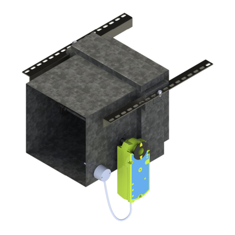
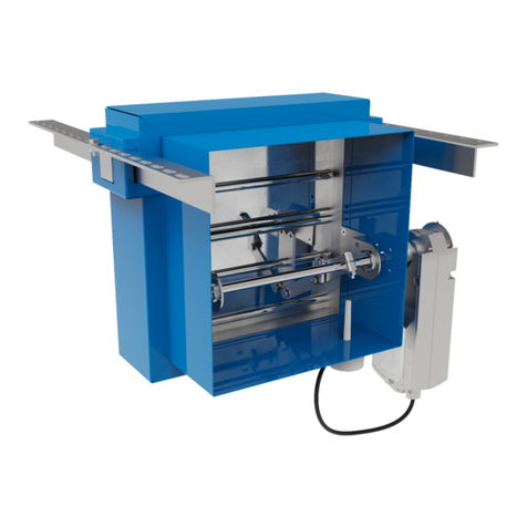
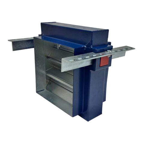
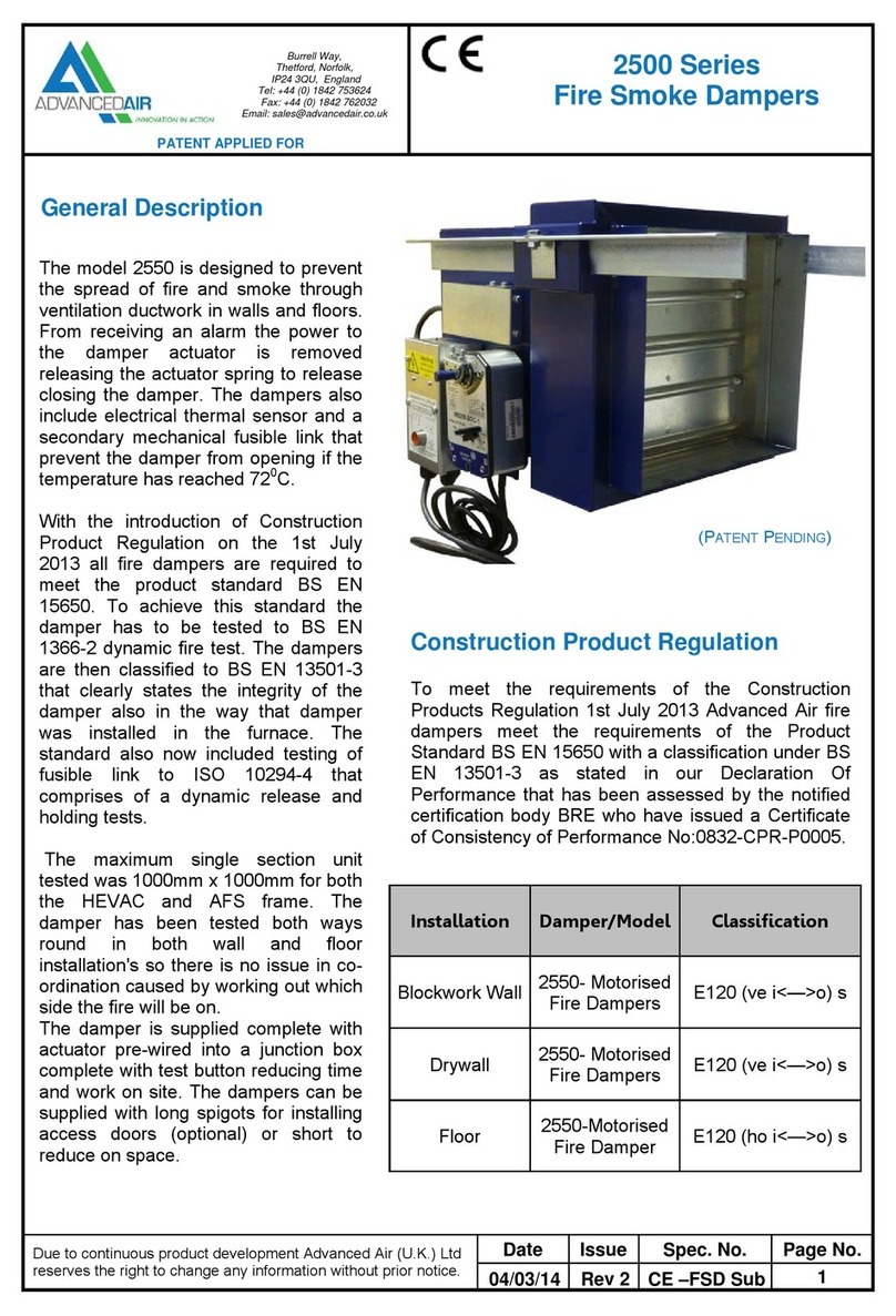
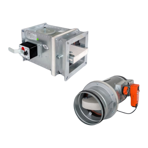
Advanced Air 0160 Series User manual

0160_IOM_1.2_Mar21_1
1
MODEL 0160
FIRE DAMPER
AIR CONTROL
INSTALLATION, OPERATION
AND MAINTENANCE MANUAL

0160_IOM_1.2_Mar21_2
2
Page
Introduction and Health & Safety 3
Fire damper – Model 0160
Two hour flexible wall – AFS with drop rods one side 4
Two hour flexible wall – AFS with drop rods in wall 5
Two hour flexible wall – multi-section AFS with drop rods two sides 6
Two hour rigid wall – AFS with drop rods one side 7
Two hour rigid wall – HEVAC 8
Two hour flexible wall – drywall plate with cleats 9
Two hour rigid floor – AFS 10
Two hour rigid floor – HEVAC 11
Operation and Maintenance 12
DW145 Fire Damper Certificate 13
Index

0160_IOM_1.2_Mar21_3
3
Introduction
Advanced Air (UK) Ltd have been manufacturing a comprehensive range of fire dampers and fire smoke
dampers since 1975. We have always taken pride in our products and tested to the highest standards,
originally to BS476 and now more stringent testing to CE labelling under the Construction Product Regulation
which was introduced 1st July 2013.
All our fire, fire smoke and smoke control dampers have been tested to BS EN 1366-2 and BS EN 1366-10.
This is to cover a variety of installations used on sites today. Under CE labelling all dampers must follow the
Product Standards BS EN 15650 and BS EN 12101-8 which ensures the product is consistent and supplied to
the same specification and standard as tested. Any deviation or changes from the installations in this manual
would require the dampers to be subject to a new test or approval sought from Local Building Control.
In line with product standards we are pleased to oer this installation manual covering installation, operation
and maintenance instructions together with Health and Safety information. We have also included within this
manual an example of the Fire Damper Certificate DW145 Inspection and Handover Check Sheet which is to
be completed by the installer. A separate certificate is required per damper.
The installation contained in this manual cover most installation on site. However, there are still installation
which Advanced Air (UK) Ltd have not yet tested. We are continually reviewing requirements and continuously
developing the products. As additional installation tests are carried out and classified, installations will be
added to this manual, and the Declaration of Performance (DoP) updated accordingly.
Health and Safety
Any instruction contained within this manual must be undertaken by competent trained personnel. When
completing the installation standard PPE should be used, steel toe cap boots, hard hat, gloves, protective
eyewear along with any other specific site or material instructions.
The size and weight of dampers vary, and it may require two or more persons to safely handle and move
them. Do not lift the dampers by the blades or the actuator.
For the installation of dampers at high level, the correct lifting equipment shall be used in accordance with
the Work at Height Regulations 2005 and specific site rules.
All waste materials should be collected and disposed of defined by the suppliers.

0160_IOM_1.2_Mar21_4
4
FIRE 0160 ADJUSTABLE FRAME SYSTEM FOR TWO HOUR FLEXIBLE SUPPORTING CONSTRUCTION SUPPORT ONE SIDE
0160 Series fire damper
AFS rail
15mm thick gypsum boards
Patented Adjustable Frame System (AFS)
incorporating bracket, bracket slot, and
Z-piece (Patent No: GB2557865)
M10 drop rod
Access door for
inspection / damper reset
Two layers of 50mm thick
140kg/m fire batt
Two hour rated flexible
supporting construction
to BS EN 1363-1:2020
Steel stud depth – 71 to 100mm
Installation sequence
4 The drywall will consist of two layers of 15mm plasterboard each side of steel studwork with an
optional mineral wool insulation. The opening will be a letterbox construction with overlapping layers
of plasterboard with an opening clearance around the damper casing in line with the above table.
5 Two M10 drop rods per fire damper shall be fitted on one side of the drywall. These should be securely
installed in line with the manufacturer’s fixing instructions in a position to match the AFS rail.
6 The drop rods should have a nut screwed on for clamping the rail from above.
7 Slide the AFS rails on each side of the damper into the brackets and insert the “Z” piece into the
bracket slot pushing it up against the underside of the rail. Insert the 8mm bolt from above into the slot
through the “Z” piece fitting the nut until tight to secure the rail.
8 The damper should be mounted centrally in the opening flush with the wall on the side with the drop
rods, as detailed in the drawing. The drop rods are to slide through the slots in the rail and a nut
screwed on to take the support of the damper rail. The damper must then be levelled and when in the
correct position the nut above the rail should be tightened against the rail.
9 The galvanised mild steel ductwork connecting to the damper spigots must overlap by up to 40mm,
leaving a minimum 10mm clearance for any duct expansion in a fire situation.
10 The galvanised mild steel ductwork connections must be sealed with an approved galvanised mild
steel ductwork sealer and fixed with low resistance fixings such as aluminium rivets that will melt at
high temperature allowing the duct to break away without eecting the integrity of the installation.
11 The connecting galvanised mild steel ductwork must be independently supported within one metre of
the connections and have been installed in accordance with DW144.
12 The gap between the damper and the wall opening will need filling with two layers of 50mm thick
140kg/m fire batt cut to an interference fit and pushed in to place. All cut edges must be sealed with
a firebatt sealant to BS EN 13501-2. A fire rated intumescent mastic to BS EN 13501-2 shall be applied
to each joint.
13 An access door should be fitted on the access side of the damper to enable the resetting of the
damper blades.
14 When the damper installation has been completed checks should be made to ensure the AFS rails are
secure and there is no movement, operation of the damper should be checked.
15 Complete DW145 Fire Damper Certificate.
PRODUCT 0160 W/ AFS RAIL APPLICATION FLEXIBLE SUPPORTING CONSTRUCTION
CLASSIFICATION REPORT NO. TBA CLASSIFICATION E120 VE I O
TESTED INSTALLATION METHOD SHOWN. DIFFERING INSTALLATION METHODS TO THIS MUST BE APPROVED BY THE BUILDING CONTROL AUTHORITY (BCA) BEFORE PROCEEDING.
Preparation
1 Ensure that the damper is kept
in a clean dry environment and
that there is no damage to the
damper.
2 Remove all the packaging and
transit ties before installation.
3 Work out the opening size to be
cut using the adjacent table.
Nom. duct width Opening width min. Opening width max.
100-1,000mm Nom. duct +194mm Nom. duct +350mm
Nom. duct height Opening height min. Opening height max.
100mm Nom. duct +100mm Nom. duct +350mm
101-300mm Nom. duct +125mm Nom. duct +375mm
301-525mm Nom. duct +150mm Nom. duct +400mm
526-700mm Nom. duct +175mm Nom. duct +425mm
701-925mm Nom. duct +200mm Nom. duct +450mm
926-1,000mm Nom. duct +225mm Nom. duct +475mm

0160_IOM_1.2_Mar21_5
5
Nom. duct width Opening width min. Opening width max.
100-1,000mm Nom. duct +194mm Nom. duct +350mm
Nom. duct height Opening height min. Opening height max.
100mm Nom. duct +100mm Nom. duct +350mm
101-300mm Nom. duct +125mm Nom. duct +375mm
301-525mm Nom. duct +150mm Nom. duct +400mm
526-700mm Nom. duct +175mm Nom. duct +425mm
701-925mm Nom. duct +200mm Nom. duct +450mm
926-1,000mm Nom. duct +225mm Nom. duct +475mm
FIRE 0160 ADJUSTABLE FRAME SYSTEM IN WALL FOR TWO HOUR FLEXIBLE SUPPORTING CONSTRUCTION
Preparation
1 Ensure that the damper is kept
in a clean dry environment and
that there is no damage to the
damper.
2 Remove all the packaging and
transit ties before installation.
3 Work out the opening size to be
cut using the adjacent table.
Patented Adjustable Frame System
(AFS) incorporating bracket, bracket
slot, and Z-piece
(Patent No: GB2557865)
Closure face board
Access door for
inspection / damper reset
0160 Series fire damper
Two layers of 50mm thick
140kg/m fire batt
M10 drop rods
15mm thick gypsum boards
Two hour rated flexible
supporting construction
to BS EN 1363-1:2020
Steel stud depth –
71 to 100mm
Installation sequence
4 The drywall will consist of two layers of 15mm plasterboard each side of steel studwork with an
optional mineral wool insulation. The opening will be a letterbox construction with overlapping layers
of plasterboard with an opening clearance around the damper casing in line with the above table.
5 Two M10 drop rods per fire damper shall be fitted centrally within the flexible wall fixed by steel anchors
into the slab or sot above. These should be securely installed in line with the manufacturer’s fixing
instructions in a position to match the AFS rail.
6 The drop rods should have a nut screwed on for clamping the rail from above.
7 Slide the AFS rails on each side of the damper into the brackets and insert the “Z” piece into the
bracket slot pushing it up against the underside of the rail. Insert the 8mm bolt from above into the slot
through the “Z” piece fitting the nut until tight to secure the rail.
8 The damper should be mounted centrally in the opening as detailed in the drawing. The drop rods
are to slide through the slots in the rail and a nut screwed on to take the support of the damper rail.
The damper must then be levelled and when in the correct position the nut above the rail should be
tightened against the rail.
9 The galvanised mild steel ductwork connecting to the damper spigots must overlap by up to 40mm,
leaving a minimum 10mm clearance for any duct expansion in a fire situation.
10 The galvanised mild steel ductwork connections must be sealed with an approved galvanised mild
steel ductwork sealer and fixed with low resistance fixings such as aluminium rivets that will melt at
high temperature allowing the duct to break away without eecting the integrity of the installation.
11 The connecting galvanised mild steel ductwork must be independently supported within one metre of
the connections and have been installed in accordance with DW144.
12 The gap between the damper and the wall opening will need filling with two layers of 50mm thick 140kg/m
fire batt cut to an interference fit and pushed in to place. All cut edges must be sealed with a firebatt
sealant to BS EN 13501-2. A fire rated intumescent mastic to BS EN 13501-2 shall be applied to each joint.
13 A closure face board of 15mm plasterboard is screwed to each side of the of the wall. It must fully cover
the fire batt and overlap the opening by 50mm.
14 An access door should be fitted on the access side of the damper to enable the resetting of the
damper blades.
15 When the damper installation has been completed checks should be made to ensure the drop rods
are secured to the cleats and there is no movement, operation of the damper should be checked.
16 Complete DW145 Fire Damper Certificate.
PRODUCT 0160 W/ AFS RAIL APPLICATION FLEXIBLE SUPPORTING CONSTRUCTION, SUPPORT IN WALL
CLASSIFICATION REPORT NO. BRE 287811C CLASSIFICATION E120 VE I O
TESTED INSTALLATION METHOD SHOWN. DIFFERING INSTALLATION METHODS TO THIS MUST BE APPROVED BY THE BUILDING CONTROL AUTHORITY (BCA) BEFORE PROCEEDING.

0160_IOM_1.2_Mar21_6
6
FIRE 0160 MULTISECTION ADJUSTABLE FRAME SYSTEM FOR FLEXIBLE SUPPORTING CONSTRUCTION
Patented Adjustable Frame System
(AFS) incorporating bracket, bracket
slot, and Z-piece
(Patent No: GB2557865)
0160 Series fire damper
AFS bracket, bracket slot,
and Z-piece
M10 drop rods
AFS rails
Access door for
inspection / damper reset
15mm thick gypsum boards
Two hour rated flexible supporting
construction to BS EN 1363-1:2020
Steel stud depth – 71 to 100mm
0160 Series fire damper
Spigot infills
Fire batt
Installation sequence
4 The drywall will consist of two layers of 15mm plasterboard each side of steel studwork with an
optional mineral wool insulation. The opening will be a letterbox construction with overlapping layers
of plasterboard with an opening clearance around the damper casing in line with the above table.
5 Two M10 drop rods per fire damper shall be fitted on both sides of the drywall. These should be
securely installed in line with the manufacturer’s fixing instructions in a position to match the AFS rail.
6 The drop rods should have a nut screwed on for clamping the rail from above. These rods will be
secured to the two top AFS rails.
7 Slide the AFS rails in all the brackets and insert the “Z” piece into the bracket slot pushing it up against
the underside of the rail. Insert the 8mm bolt from above into the slot through the “Z” piece fitting the
nut until tight to secure the rail.
8 Additional drop rods should then be passed through the top and bottom rails and fully tightened.
9 The damper should be mounted centrally in the opening flush with the wall on one side. The anchored
drop rods are to slide through the top rails and nuts are screwed on to take the support. The damper must
then be levelled and when in the correct position the nut above the rail should be tightened against the rail.
10 The galvanised mild steel ductwork connecting to the damper spigots must overlap by up to 40mm,
leaving a minimum 10mm clearance for any duct expansion in a fire situation.
11 The galvanised mild steel ductwork connections must be sealed with an approved galvanised mild
steel ductwork sealer and fixed with low resistance fixings such as aluminium rivets that will melt at
high temperature allowing the duct to break away without eecting the integrity of the installation.
12 The connecting galvanised mild steel ductwork must be independently supported within one metre of
the connections and have been installed in accordance with DW144.
13 The gap between the damper and the wall opening will need filling with two layers of 50mm thick
140kg/m fire batt cut to an interference fit and pushed in to place. All cut edges must be sealed with
a firebatt sealant to BS EN 13501-2. A fire rated intumescent mastic (to BS EN 13501-2) shall be applied
to each joint.
14 An access door should be fitted on the access side of the damper to enable the resetting of the
damper blades.
15 When the damper installation has been completed checks should be made to ensure the AFS rails are
secured to the damper and there is no movement, operation of the damper should be checked.
16 Complete DW145 Fire Damper Certificate.
Preparation
1 Ensure that the damper is kept
in a clean dry environment and
that there is no damage to the
damper.
2 Remove all the packaging and
transit ties before installation.
3 Work out the opening size to be
cut using the adjacent table.
Nom. duct width Opening width min. Opening width max.
1001-2,000mm Nom. duct +194mm Nom. duct +350mm
Nom. duct height Opening height min. Opening height max.
1001-1146mm Nom. duct +150mm Nom. duct +400mm
1147-1521mm Nom. duct +175mm Nom. duct +425mm
1552-1996mm Nom. duct +200mm Nom. duct +450mm
1997-2000mm Nom. duct +225mm Nom. duct +475mm
PRODUCT 0160 MULTISECTION W/AFS APPLICATION FLEXIBLE SUPPORTING CONSTRUCTION
CLASSIFICATION REPORT NO. TBA CLASSIFICATION E120 VE I O
TESTED INSTALLATION METHOD SHOWN. DIFFERING INSTALLATION METHODS TO THIS MUST BE APPROVED BY THE BUILDING CONTROL AUTHORITY (BCA) BEFORE PROCEEDING.
While we have tested a damper 2,000 x 2,000mm, larger sizes can be supplied but the installation will need to be checked by a
competent structural engineer as stated in the Extended Fields of Application BS EN 15882-2:2015. With all larger sizes there should
be a risk assessment carried out and a full method statement documented to ensure the correct lifting gear and safety precautions
are put in place prior to the installation being carried out.

0160_IOM_1.2_Mar21_7
7
Nom. duct width Opening width min. Opening width max.
100-1,000mm Nom. duct +194mm Nom. duct +350mm
Nom. duct height Opening height min. Opening height max.
100mm Nom. duct +100mm Nom. duct +350mm
101-300mm Nom. duct +125mm Nom. duct +375mm
301-525mm Nom. duct +150mm Nom. duct +400mm
526-700mm Nom. duct +175mm Nom. duct +425mm
701-925mm Nom. duct +200mm Nom. duct +450mm
926-1,000mm Nom. duct +225mm Nom. duct +475mm
FIRE 0160 ADJUSTABLE FRAME SYSTEM FOR TWO HOUR RIGID SUPPORTING CONSTRUCTION
Patented Adjustable Frame System (AFS)
incorporating bracket, bracket slot, and
Z-piece (Patent No: GB2557865)
Access door for
inspection / damper reset
Two layers of 50mm thick
140kg/m fire batt
Two hour rated blockwork,
masonry or homogeneous
concrete wall to
BS EN 1363-1:2020
AFS rail
M10 drop rod
PRODUCT 0160 W/ AFS RAIL APPLICATION RIGID CONSTRUCTION
CLASSIFICATION REPORT NO. TBA CLASSIFICATION E120 VE I O
TESTED INSTALLATION METHOD SHOWN. DIFFERING INSTALLATION METHODS TO THIS MUST BE APPROVED BY THE BUILDING CONTROL AUTHORITY (BCA) BEFORE PROCEEDING.
Preparation
1 Ensure that the damper is kept
in a clean dry environment and
that there is no damage to the
damper.
2 Remove all the packaging
before installation.
3 Work out the opening size to be
cut using the adjacent table.
Installation sequence
4 Two M10 drop rods shall be fitted on one side of the drywall.
5 The drop rods should have a nut screwed on for clamping the rail from above.
6 Slide the AFS rails on each side of the damper into the brackets and insert the “Z” piece into the
bracket slot pushing it up against the underside of the rail. Insert the 8mm bolt from above into the slot
through the “Z” piece fitting the nut until tight to secure the rail.
7 The damper should be centrally positioned in the opening with the access side flush with the wall,
as detailed in the drawing. The drop rods are to slide through the slots in the rail and a nut screwed
on to take the support of the damper rail. The damper must then be levelled and when in the correct
position the nut above the rail should be tightened against the rail.
8 The galvanised mild steel ductwork connecting to the damper spigots must overlap by up to 40mm,
leaving a minimum 10mm clearance for any duct expansion in a fire situation.
9 The galvanised mild steel ductwork connections must be sealed with an approved galvanised mild
steel ductwork sealer and fixed with low resistance fixings such as aluminium rivets that will melt at
high temperature allowing the duct to break away without aecting the integrity of the installation.
10 The connecting galvanised mild steel ductwork must be independently supported within one metre of
the connections and have been installed in accordance with DW144.
11 The gap between the damper and the wall opening will need filling with two layers of 50mm thick
140kg/m fire batt cut to an interference fit and pushed in to place. A fire rated mastic will be applied
to each joint.
12 An access door should be fitted on the access side of the damper to enable the resetting of the
damper blades.
13 When the damper installation has been completed checks should be made to ensure the AFS rails are
secure and there is no movement, operation of the damper should be checked.
14 Complete DW145 Fire Damper Certificate.

0160_IOM_1.2_Mar21_8
8
FIRE 0160 HEVAC FOR RIGID SUPPORTING CONSTRUCTION WALL
0160 Series
fire damper
HEVAC frame
4:1 mortar mix
Lintel
150mm thickness
two hour rated rigid
supporting construction
to BS EN 1363-1:2020
Turnback tabs
Ductwork
support
Access door for
inspection / damper reset
Installation sequence
4 In the opening, mark the positions for the turnback ties on the HEVAC frame.
5 Create 20mm deep pockets for the HEVAC tabs to be located in.
6 Oer up the damper into the opening and support from the bottom of the damper so that it sits
centrally within the opening and has an even space on all four sides.
7 Bend the HEVAC tabs so that they lock into the pockets.
8 A 4:1 mortar mix can then be gradually applied between the wall and the damper, ensuring the mortar
is only filled up to the HEVAC frame and not the damper spigots. This ensures the damper can move
within the HEVAC frame.
9 The galvanised mild steel ductwork connecting to the damper spigots must overlap by up to 40mm,
leaving minimum 10mm clearance for any duct expansion in a fire situation.
10 The galvanised mild steel ductwork connections must be sealed with an approved galvanised mild
steel ductwork sealer and fixed with low resistance fixings such as aluminium rivets that will melt at
high temperature allowing the duct to break away with aecting the integrity of the installation.
11 The connecting galvanised mild steel ductwork must be independently supported within one metre of
the connections and have been installed in accordance with DW144.
12 An access door should be fitted on the access side of the damper to enable the resting of the damper
blades.
13 When the damper installation has been completed, checks should be made to ensure the damper is
secure and there is no movement, operation of the damper should be checked.
14 Complete DW145 Fire Damper Certificate.
Preparation
1 Ensure that the damper is kept
in a clean dry environment and
that there is no damage to the
damper.
2 Remove all the packaging and
transit ties before installation.
3 Work out the opening size to be
cut using the adjacent table.
Nom. duct width Opening width min. Opening width max.
100-1,000mm Nom. duct +160mm Nom. duct +185mm
Nom. duct height Opening height min. Opening height max.
100mm Nom. duct +160mm Nom. duct +185mm
101-300mm Nom. duct +185mm Nom. duct +210mm
301-525mm Nom. duct +210mm Nom. duct +235mm
526-700mm Nom. duct +235mm Nom. duct +260mm
701-925mm Nom. duct +260mm Nom. duct +285mm
926-1,000mm Nom. duct +285mm Nom. duct +310mm
PRODUCT 0160 W/ HEVAC FRAME APPLICATION RIGID SUPPORTING CONSTRUCTION
CLASSIFICATION REPORT NO. BRE 262247B CLASSIFICATION E120 VE I O
TESTED INSTALLATION METHOD SHOWN. DIFFERING INSTALLATION METHODS TO THIS MUST BE APPROVED BY THE BUILDING CONTROL AUTHORITY (BCA) BEFORE PROCEEDING.

0160_IOM_1.2_Mar21_9
9
FIRE 0160 DRYWALL PLATE INSTALLATION FOR FLEXIBLE SUPPORTING CONSTRUCTION
Drywall plate
M10 drop rod
Cleat
Access door for
inspection / damper reset
Two layers of 50mm thick
140kg/m fire batt
15mm thick gypsum boards
Two hour rated flexible
supporting construction
to BS EN 1363-1:2020
Steel stud depth – 71 to 100mm
0160 Series fire damper
Installation sequence
4 The drywall will consist of two layers of 15mm plasterboard each side of steel studwork with an
optional mineral wool insulation. The opening will be a letterbox construction with overlapping layers
of plasterboard with an opening clearance around the damper casing in line with the above table.
5 Two M10 drop rods per fire damper shall be fitted on one side of the drywall. These should be securely
installed in line with the manufacturer’s fixing instructions in a position to match the cleats on the dry
wall damper frame.
6 The drop rods should have a nut screwed on for clamping the cleat from above.
7 The damper should be mounted centrally in the opening flush with the dry wall frame on the side with
the drop rods, as detailed in the drawing. The drop rods are to slide through the holes in the cleats
and a nut screwed on to take the support of the damper. The damper must then be levelled and when
in the correct position the nut above the rail should be tightened against the cleat.
8 The galvanised mild steel ductwork connecting to the damper spigots must overlap by up to 40mm,
leaving a minimum 10mm clearance for any duct expansion in a fire situation.
9 The galvanised mild steel ductwork connections must be sealed with an approved galvanised mild
steel ductwork sealer and fixed with low resistance fixings such as aluminium rivets that will melt at
high temperature allowing the duct to break away without eecting the integrity of the installation.
10 The connecting galvanised mild steel ductwork must be independently supported within one metre of
the connections and have been installed in accordance with DW144.
11 The gap between the damper and the wall opening will need filling with two layers of 50mm thick
140kg/m fire batt cut to an interference fit and pushed in to place. All cut edges must be sealed with
a firebatt sealant to BS EN 13501-2. A fire rated intumescent mastic (to BS EN 13501-2) shall be applied
to each joint.
12 An access door should be fitted on the access side of the damper to enable the resetting of the
damper blades.
13 When the damper installation has been completed checks should be made to ensure the drop rods
are secured to the cleats and there is no movement, operation of the damper should be checked.
14 Complete DW145 Fire Damper Certificate.
Preparation
1 Ensure that the damper is kept
in a clean dry environment and
that there is no damage to the
damper.
2 Remove all the packaging and
transit ties before installation.
3 Work out the opening size to be
cut using the adjacent table.
Nominal duct width Opening width maximum
100-1,000mm Nominal duct +90mm
Nominal duct height Opening height maximum
100mm Nominal duct +90mm
101-300mm Nominal duct +115mm
301-525mm Nominal duct +140mm
526-700mm Nominal duct +165mm
701-925mm Nominal duct +190mm
926-1,000mm Nominal duct +215mm
PRODUCT 0160 W/ DRYWALL PLATE APPLICATION FLEXIBLE SUPPORTING CONSTRUCTION
CLASSIFICATION REPORT NO. 2019 EFECTIS R002230 CLASSIFICATION E120 VE I O
TESTED INSTALLATION METHOD SHOWN. DIFFERING INSTALLATION METHODS TO THIS MUST BE APPROVED BY THE BUILDING CONTROL AUTHORITY (BCA) BEFORE PROCEEDING.

0160_IOM_1.2_Mar21_10
10
PRODUCT 0160 W/AFS APPLICATION RIGID SUPPORTING CONSTRUCTION FLOOR
CLASSIFICATION REPORT NO. 2013EFECTISRO511C CLASSIFICATION E120 HO I O
TESTED INSTALLATION METHOD SHOWN. DIFFERING INSTALLATION METHODS TO THIS MUST BE APPROVED BY THE BUILDING CONTROL AUTHORITY (BCA) BEFORE PROCEEDING.
FIRE 0160 ADJUSTABLE FRAME SYSTEM FOR RIGID SUPPORTING CONSTRUCTION FLOOR
Patented Adjustable Frame System (AFS)
incorporating bracket, bracket slot, and Z-piece
(Patent No: GB2557865)
Access door
for inspection /
damper reset
0160 Series
fire damper
Suitable
bolts
Supporting
Z-angle
Three layers of
50mm fire batt
Min. 150mm thick
two hour rated
rigid supporting
construction to
BS EN 1363-1:2020
AFS rail
(40x40x4mm)
by others
Preparation
1 Ensure that the damper is kept
in a clean dry environment and
that there is no damage to the
damper.
2 Remove all the packaging and
transit ties before installation.
3 Work out the opening size to be
cut using the adjacent table.
Nom. duct width Opening width min. Opening width max.
100-1,000mm Nom. duct +100mm Nom. duct +350mm
Nom. duct height Opening height min. Opening height max.
100mm Nom. duct +140mm Nom. duct +350mm
101-300mm Nom. duct +165mm Nom. duct +375mm
301-525mm Nom. duct +190mm Nom. duct +400mm
526-700mm Nom. duct +215mm Nom. duct +425mm
701-925mm Nom. duct +240mm Nom. duct +450mm
926-1,000mm Nom. duct +265mm Nom. duct +475mm
Installation sequence
4 Install 40mm x 40mm x 4mm angle through the AFS brackets ensuring they are of sucient length to
extend past the opening on each side by 100mm.
5 Position the dampers evenly in the centre of the opening.
6 Secure the angles to the floor. Mark the hole positions on the angle at least 50mm away from the
opening. Drill and install M8 steel anchors and bolt the angle to the floor.
7 The galvanised mild steel ductwork connecting to the damper spigot must overlap by 40mm, leaving
a 10mm clearance for any duct expansion in a fire situation.
8 The galvanised mild steel ductwork connections must be sealed with an approved galvanised mild
steel ductwork sealer and fixed with low resistance fixings such as aluminium rivets that will melt at
high temperature allowing the duct to break away without aecting the integrity of the installation.
9 ‘Z’ angles are required to support the first layer of fire batt. These measure 50mm x 150mm x 50mm
by 100mm wide. They are to be positioned on all fire batt joints on the bottom layer and evenly spaced
on a 500mm minimum pitch.
10 The gap between the damper and the floor opening will need filling with three layers of 50mm thick
140kg/m3fire batt cut to an interference fit and pushed into place. All cut edges must be sealed with a
fire batt sealant to BS EN 13501-2. A fire rated intumescent mastic to BS EN 13501-2 shall be applied to
each joint.
11 The connecting galvanised mild steel ductwork must be independently supported within one metre of
the connections and have been installed in accordance with DW144.
12 An access door should be fitted on the access side of the damper for inspection and maintenance.
13 When the damper installation is complete the operation of the damper should be checked.
14 Complete DW145 Fire Damper Certificate.

0160_IOM_1.2_Mar21_11
11
PRODUCT 0160 W/HEVAC APPLICATION RIGID CONSTRUCTION FLOOR
CLASSIFICATION REPORT NO. BRE 287811D CLASSIFICATION E120 HO I O
TESTED INSTALLATION METHOD SHOWN. DIFFERING INSTALLATION METHODS TO THIS MUST BE APPROVED BY THE BUILDING CONTROL AUTHORITY (BCA) BEFORE PROCEEDING.
FIRE 0160 HEVAC FOR RIGID SUPPORTING CONSTRUCTION FLOOR
HEVAC frame 0160 Series fire damper
Turnback tabs
Fire batt
Access door
for inspection /
damper reset
Rigid construction
4:1 mortar mix
Installation sequence
4 In the opening, mark the positions for the turnback tabs on the HEVAC frame, making sure that the
HEVAC casing will sit flush with the floor surface.
5 Create 20mm deep pockets for the HEVAC tabs to be located in.
6 Oer up the damper into the opening and support from below or clamp angles spanning the opening.
7 Bend the HEVAC tabs so that they lock into the pockets.
8 Fire batt of a minimum 25mm thickness and density of 140kg/m shall be installed under the damper
frame to serve as shuttering to facilitate installation of the penetration seal all around the damper.
9 A 4:1 mortar mix can then be gradually applied between the floor and the damper, ensuring the mortar
is only filled up to the HEVAC frame and not the damper spigots. This ensures the damper can move
within the HEVAC frame.
10 The fire batt shall remain in situ after the mortar has been applied.
11 The galvanised mild steel ductwork connecting to the damper spigots must overlap by up to 40mm,
leaving minimum 10mm clearance for any duct expansion in a fire situation.
12 The galvanised mild steel ductwork connections must be sealed with an approved galvanised mild
steel ductwork sealer and fixed with low resistance fixings such as aluminium rivets that will melt at
high temperature allowing the duct to break away without aecting the integrity of the installation.
13 The connecting galvanised mild steel ductwork must be independently supported within one metre of
the connections and have been installed in accordance with DW144.
14 An access door should be fitted on the access side of the damper to enable the resetting of the
damper blades.
15 When the damper installation has been completed, checks should be made to ensure the damper is
secure and there is no movement, operation of the damper should be checked.
16 Complete DW145 Fire Damper Certificate.
Preparation
1 Ensure that the damper is kept
in a clean dry environment and
that there is no damage to the
damper.
2 Remove all the packaging and
transit ties before installation.
3 Work out the opening size to be
cut using the adjacent table.
Nom. duct width Opening width min. Opening width max.
100-1,000mm Nom. duct +160mm Nom. duct +185mm
Nom. duct height Opening height min. Opening height max.
100mm Nom. duct +160mm Nom. duct +185mm
101-300mm Nom. duct +185mm Nom. duct +210mm
301-525mm Nom. duct +210mm Nom. duct +235mm
526-700mm Nom. duct +235mm Nom. duct +260mm
701-925mm Nom. duct +260mm Nom. duct +285mm
926-1,000mm Nom. duct +285mm Nom. duct +310mm

0160_IOM_1.2_Mar21_12
12
• To reset the damper, the bottom blade will need to be pushed away from the locking ramp, then
keeping the bottom blade level push the blade pack upwards into the top of the damper. When the top
has been reached the EML fusible link can then be swung into position and secured with the latch. NB;
• For larger dampers independent supports may be required to hold the blade pack in position
whilst securing the latch.
• Dampers 149mm and under will have a ring pull fitted to enable the blade to be pulled away from
the locking ramps, on these sizes the release latch is on the opposite side of the locking ramps.
This is the reason access doors are required on both sides of the damper.
• Refit the access door and complete any relevant reports.
Initial operating check
The 0160 fire damper should only be commissioned once installation has been completed.
The damper should be inspected thoroughly to ensure that it is clean and free of any internal debris before
the damper is tested as per the following instructions;
• Remove the access door or doors, (on some installations access doors are required on both sides of
the damper to enable the resetting of the damper). If a transportation tie is still fitted to the link, remove it.
• The 0160 fire damper is fitted with an EML fusible link, this link is provided with a release latch on the
access side of the damper. To test the damper the latch is released allowing the blades to drop and
the link is retained on a pivot opposite to the latch.
• Before testing the damper, check that the blade pack is sitting level to the drop direction, if they are
sitting uneven before testing this could result in damage to the blades and spring system.
0160 OPERATION AND MAINTENANCE
• Visually inspect the damper blades to ensure that they are all
interlocked, that the springs are straight and that the bottom damper is
locked into the locking ramp on both sides of the damper. NB;
• On vertically installed dampers 750 high and above, it is OK for
these not to have springs and locking ramps fitted.
Maintenance
0160 fire dampers are installed as a life safety product and it is essential that they are always maintained so
they are in a clean working condition. In accordance with BS9999 Annex W.1 maintenance and inspection
should be undertaken annually.
Maintain the dampers as follows;
• Remove the access door to internally inspect the damper.
• Visually inspect all damper components for signs of corrosion, obstructions and build-up of dirt/dust.
• Remove any obstructions, wipe away all dirt and dust from the damper blades, sides and duct surfaces.
• Examine the EML fusible link to ensure that no corrosion has occurred.
• If the EML fusible link is required to be replaced, then should be done as follows:
• Use independent supports or hold the damper blade pack in position.
• Release the EML latch, the link will now drop and pivot on the opposite side.
• To release the link from the retaining bracket, hold the link and lift it upwards in its retaining slot
then pull it away from the bracket.
• To fit a new link push it into the slot of the bracket on the non-access side of the damper.
• Rotate it upwards and secure with the release latch
• Test and check the damper by the method detailed in the ‘Initial Operating Check’.
• Refit the access door and complete maintenance reports as appropriate.
• Release the latch on the EML, the blades will
drop quickly under the force of the springs
and gravity, ensure that hands and arms are
away from the direction of blade travel.
Release latch
Bottom blade
locked into ramp

0160_IOM_1.2_Mar21_13
13
Fire Damper Certificate
CE-020
CE Certification
Rev 01
June 2019
S Manning
DW 145 Inspection & Handover Check Sheet to be completed by the installer with a separate
certificate for each damper.
No.
Question
Guidelines
Tick
1 Are the dampers the correct type?
Fire Damper Model 0160, 0400MAN
Fire Damper Model 2550, 2530, 26SCD
and 0400FME
2 Are the dampers correctly identified?
Identification label clearly shows the
damper individual reference number
3 Are the dampers located correctly?
The damper position matches the
position as detailed on the
manufactures installation instructions
4
Have supports for both the damper and
the adjacent ductwork been installed in
accordance with the approved method?
5
Are the dampers fitted in the correct
orientations?
The dampers are installed the correct
way up relative to airflow and access
6 Is access, through the ductwork to the
damper unobstructed?
There is unobstructed space to allow
safe access to damper, also through
ceiling void and adjacent services
7
Confirm the space around the damper has
not been used for the passage of other
services
The presence of other services will
invalidate the installation method
8
Using the access opening provided,
confirm that the damper has been left in
the open position
9
Release the damper catch to simulate the
thermal release mechanism (damper drop
test)
Ensure the blade operation is free from
interference
10 Check damper blades for damage
With the damper in the closed position
inspect for damage
11 Re-set damper and replace access panel
After resetting check that if supplied
the visual position indicator is correct
12 Is the fire barrier and penetration seal
complete?
Confirm at handover if installation is
complete and if no then other trades
will be required to finish
13 Handover damper installation for
commissioning
Obtain relevant acceptance of the
damper installation from the
nominated person responsible
Project
Installer Name
Damper ID No:
Company
Location
Date
Type
I hereby confirm the damper detailed has been installed and
tested according to the manufactures recommendations
Model No:
Signature
Other manuals for 0160 Series
1
Table of contents
Other Advanced Air Fire And Smoke Damper manuals
Popular Fire And Smoke Damper manuals by other brands

Mandik
Mandik FDMQ manual

Honeywell Home
Honeywell Home TrueZONE Bypass installation instructions

mercor
mercor mcr FID S c/P Series Operation and maintenance manual

MAT
MAT Roto-Twist RT-150 Installation, operation & maintenance instructions

mercor
mercor mcr ZIPP Operation and maintenance manual

Schako
Schako BSK-RPR-EU Series Technical documentation