Wildeboer FR90 User manual

Maintenance-free
FR90 re dampers
■ Sizes ∅ 100 mm to ∅ 800 mm
■ For universal use with a wide range of applications
■ Fire classication: EI 30/60/90/120 (ve - ho, i ↔ o) S C10ooo
■ Hygiene certicate
■ Environmental Product Declaration according to ISO 14025 and EN 15804
User Manual 5.3 (2018-07) 1
The German original version of this document shall prevail

User Manual 5.3 (2018-07) 2 Subject to change
Series FR92
FR90 re dampers
Features and characteristics
Single-piece sheet steel casing
galvanized - longitudinal seam welded - extremely robust
airtight, smoke-proof
Leak tightness class C
according to EN 1751
Option: Epoxy resin powder coating
Break-resistant
damper blade
with elastomer lip seal
airtight, leak tightness class 3
according to EN 1751
Options:
• Metal cover made of galvanized steel
• Metal cover made of 1.4301 stainless steel
Large free cross-section
Maximum volume ows
Minimum pressure drop
Extremely low sound power level
Nominal sizes [mm]
DN 100 to DN 800
Thermal-mechanical
release mechanism
for single handed operation
Option:
Electric actuators, also explosion-protected
Release mechanism and axis of
the damper blade rotatable 360°
Two control openings (inspection openings)
for viewing both sides of the damper blade
Fully enclosed:
•Operation unit
•Release mechanism
• Release element
Lip seals
All-round enclosed
thermal release elements 70°C or 95°C
Option:
Corrosion-resistant release element 70°C

User Manual 5.3 (2018-07) 3Subject to change Series FR92
FR90 re dampers
Description
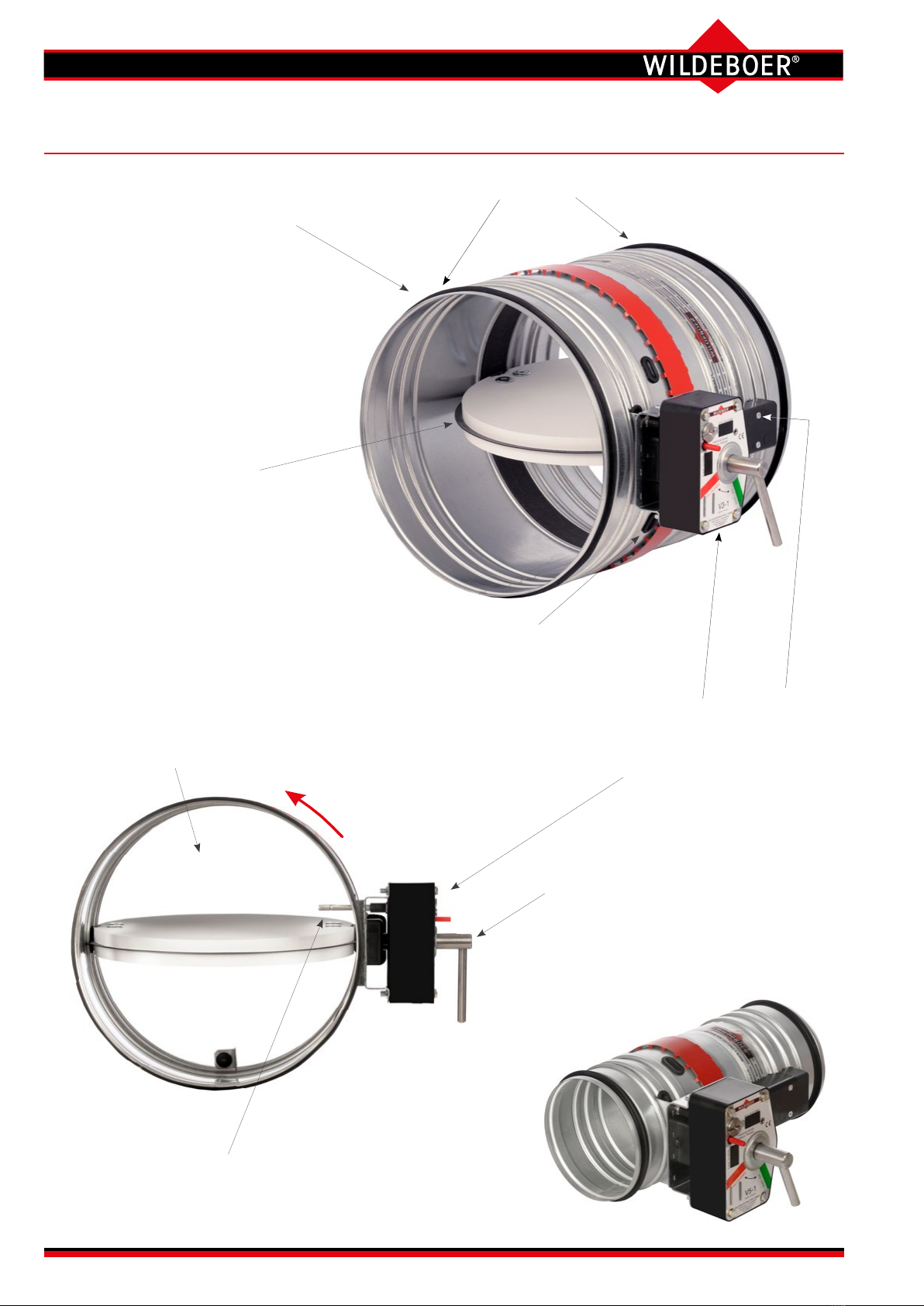
All-round single-piece galvanized sheet steel casing.
Casing tightness class C according to EN 1751.
Moulded push-t connections with lip seals for spiral
duct according to DIN 24145, for exible pipe and for
similar ducts of ventilation and air conditioning systems.
All-round press-moulded beading over the whole length
of casing ensures necessary strength and free move-
ment of the damper blade even with large dimensions.
Low pressure drop and a very low noise level are thus
achieved.
Replaceable damper blade made of high-tempera-
ture-resistant, abrasion-proof calcium silicate with
wear-resistant elastomer seals. Damper blade leak tight-
ness class 3 according to EN 1751.
Option: Casing with powder coating. ⇒ see page 6
Option: Damper blade with metal cover (not replaceable)
made of galvanized steel or 1.4301 stainless steel.
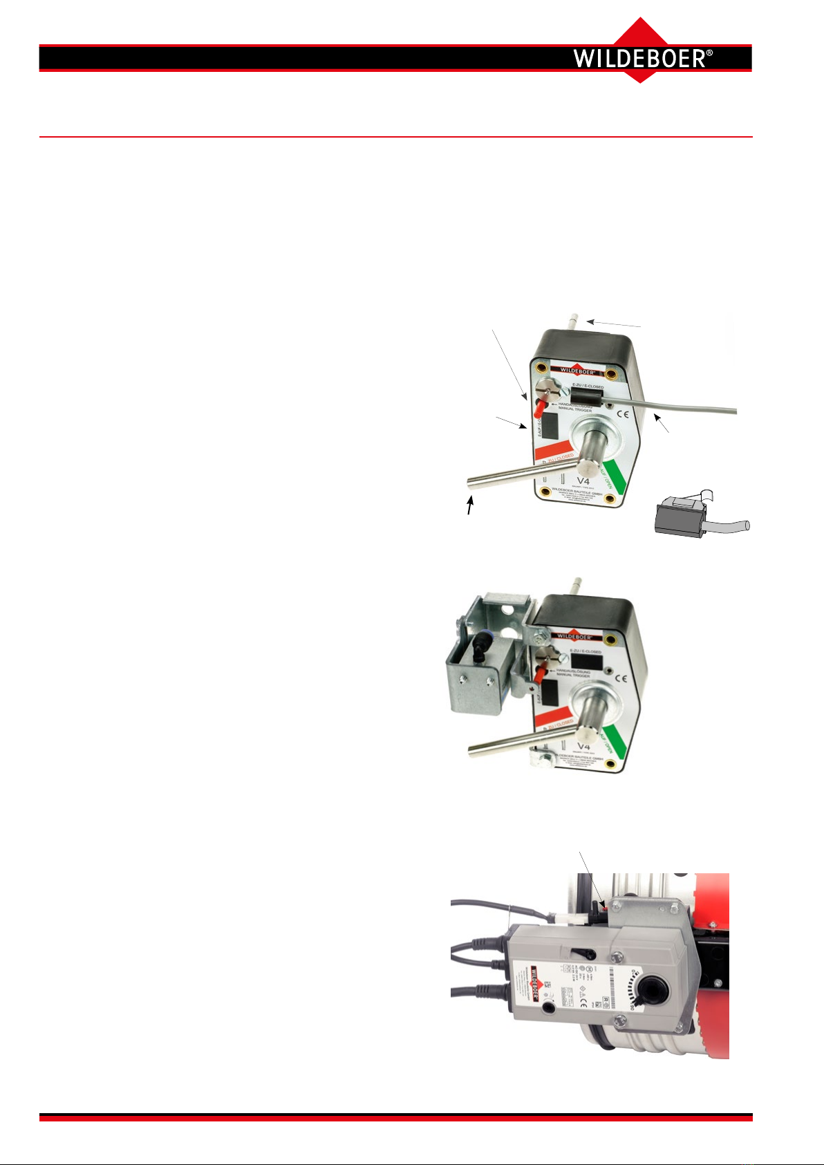
Enclosed, maintenance-free drive mechanism in the
area of the casing wall as a self-locking transmission
for break-proof torque transmission. Sealed drive axles
made of stainless steel, with red metal bearings. Ther-
mal release mechanisms for 70°C or 95°C nominal tem-
perature. The operation units can be actuated manually
or electrically. ⇒ see pages 4 and 5
Release mechanisms, operation units and electric actu-
ators are enclosed and with a spring return. They are
maintenance-free, can be connected in a form-locking
or force-tting manner, are easy to replace and can be
easily retrotted as required.
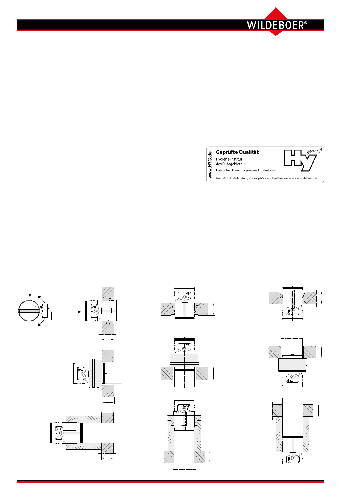
For installation with horizontal or vertical damper blade
axles and in intermediate positions. Air ows are pos-
sible from each connection side.
Connection to ventilation ducts made from non-combus-
tible or combustible materials is possible, also protective
grille.
Installation spacings from 15 mm possible.
Maintenance-free FR90 re dampers according to EN 15650
Fire classications: EI 30/60/90/120 (ve - ho, i ↔ o) S C10ooo
Declaration of performance: DoP no.: CPR/FR90/003
EU Declaration of Conformity according to Directive 2014/34/EU for
use in potentially explosive atmospheres
Environmental Product Declaration ISO 14025, EN 15804:
EPD-WWB-20130082-IBA1-DE
Additional national approvals in
Germany:
• Building materials: Z-56.4212-993
FR90 re dampers are essentially
made from non-combustible build-
ing materials.
• Air transfer applications:
Z-6.50-2133
Z-19.18-2241
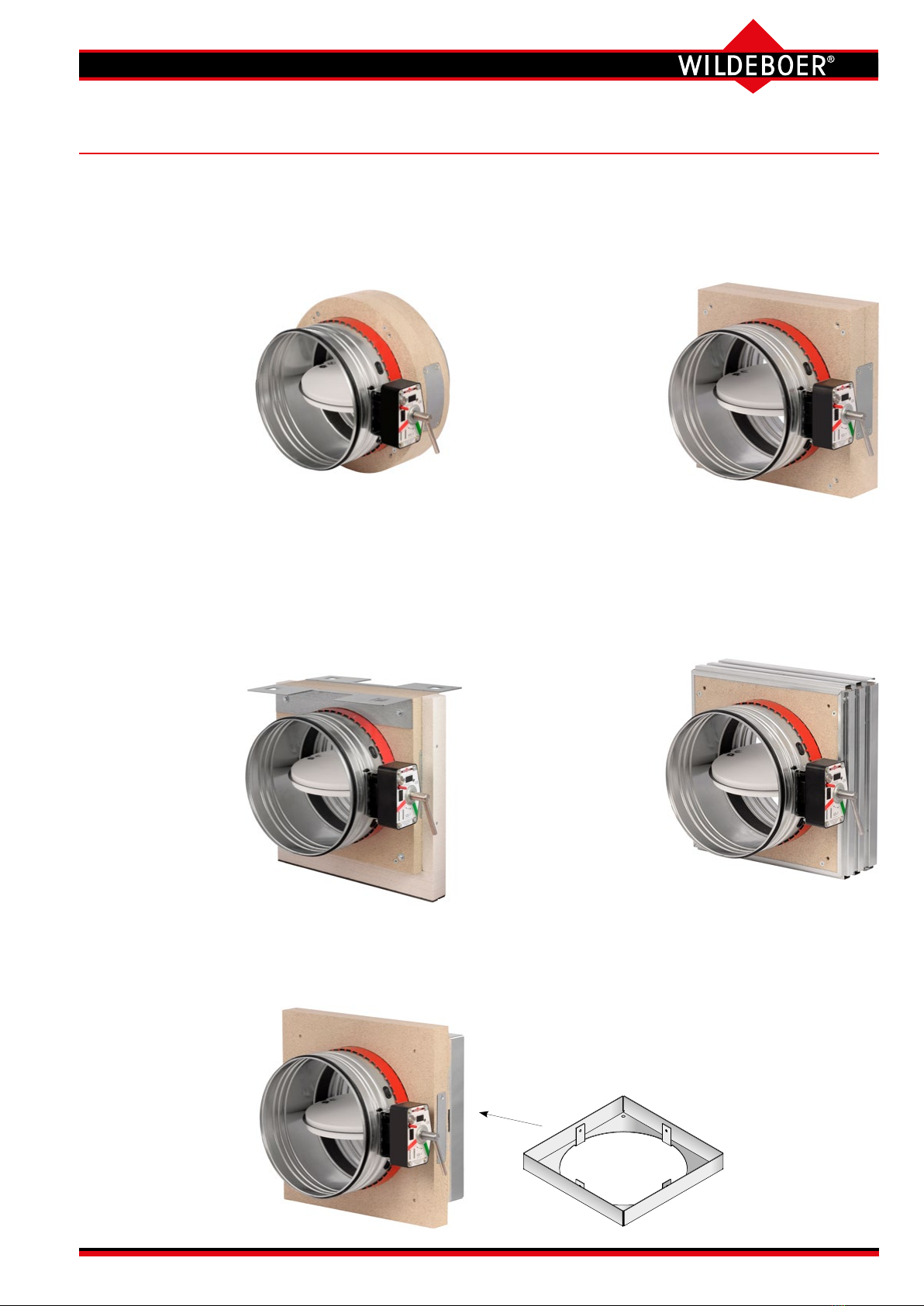
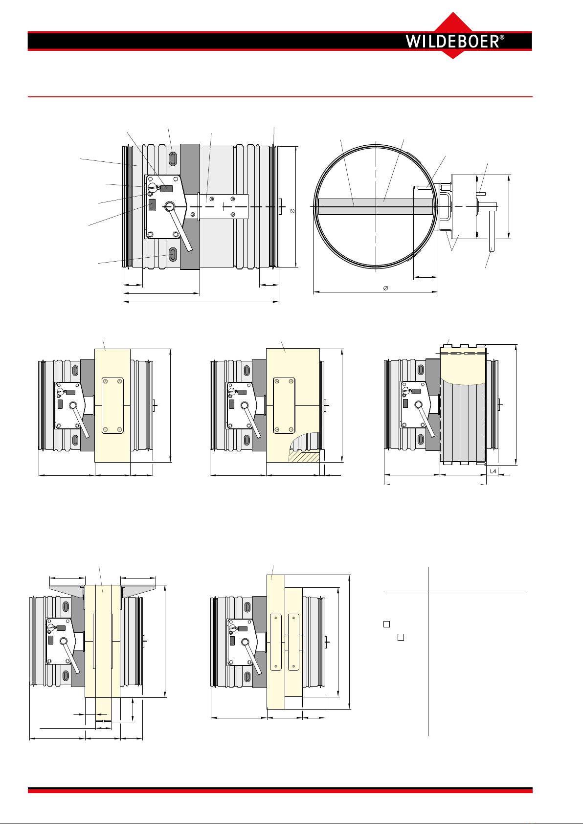
•Circular installation subframe RR (RR100, RR150) for
simplied installation in circular installation openings.
Only up to DN 315! ⇒ see pages 7, 8, 13, 14, 22, 42 to 44
•
Rectangular installation subframe RE (RE100,
RE150) for simplied installation in rigid walls and
ceilings and in metal stud walls with cladding on both
sides.
⇒ see pages 7, 8, 13, 14, 20 to 22, 42 to 44
• With rectangular installation subframe RH (RH100,
RH150) for installation in wooden walls and wooden
ceilings. ⇒ see pages 7, 8, 28 to 31, 42 to 45
• Rectangular installation subframe RH150 for instal-
lation in ceilings with steel frames.
⇒ see pages 7, 8, 33, 34, 42 to 45
•Mounting frame AE for mounting on rigid walls and
ceilings and walls with cladding on one side and with
or without metal studs.
⇒ see pages 7, 8, 15, 26, 27, 35, 42 to 44
•Installation subframe ER6 for sliding ceiling connec-
tions with drops of up to 40 mm in metal stud walls
with cladding on both sides.
⇒ see pages 7, 8, 23 to 25, 42, 43
•Mounting frame RV for connection to ventilation
ducts with re resistance period. Installation remote
from rigid walls and ceilings and metal stud walls.
⇒ see pages 7, 8, 36 to 39, 42 to 45
Nominal sizes [mm] DN:
100 - 125 - 140 - 160 - 180 - 200 - 224 - 250 - 280 - 315 - 355 - 400 - 450 - 500 - 560 - 630 - 710 - 800
Options:
FR90 re dampers in these sizes achieve re resistance periods of up to 120 minutes if they are installed in accordance with
the following stipulations. Installation types in, on or remote from rigid walls and ceilings or metal stud walls, in wooden walls and
ceilings and in ceilings with steel frames with a minimum thickness and re resistance period. If the walls, ceilings have a re
resistance period of less than 120, 90 or 60 minutes, the re resistance period of the FR90 re dampers is reduced accordingly;
partly if the minimum thickness is lower.

User Manual 5.3 (2018-07) 4 Subject to change
Series FR92
FR90 re dampers
Release mechanisms and actuators (1)
Thermal-mechanical release mechanism - Standard -
with 70°C release element, protection class IP54.
Option: with coated 70°C release element.
Option: with coated 95°C release element.
Option: with limit switch
E Changeover with gold-plated contacts for 5 A at
250 VAC or 24 VDC; protection class IP67;
1m silicone free connection cable 3 x0.34 mm².
One or two can be plugged in for the CLOSED and/or OPEN
position indicator instead of blind caps.
Enclosed release
element can be
replaced from the
front.
Blind cap can
be replaced with
the OPEN limit
switch.
Manual release
“Red button”
Lever for opening
the re damper.
Inserted
CLOSED limit
switch.
FR90 re dampers, series FR92, are tted with maintenance-free thermal-mechanical release mechanisms or with
thermal-electrical release mechanisms on the spring return actuators. Release occurs at a nominal temperature of
70°C or 95°C. Coated release elements provide increased corrosion protection.
Electric spring return actuators also close the re dampers if the supply voltage is interrupted. They reopen the re
dampers as soon as the voltage is present again.
Release mechanisms and operation units can be replaced on site!
Release mechanism and remote release with lift cylinder
Option: with additional remote release based on the:
closed circuit principle. The re dampers must be opened man-
ually, and close after the electrical supply voltage is interrupted.
GU24 with magnetic clamp 24 V
DC; 1.6
W;
100%
duty cycle; IP42.
WU220 with magnetic clamp 230 V
AC; 4
VA;
100%
duty cycle; IP42.
Open circuit principle. The re dampers must be opened man-
ually, and close by means of electrical or pneumatic stimulus.
G24 with lifting solenoid 24 V
DC; 3.5
W; 100%
duty
cycle; IP42.
W220 with lifting solenoid 230 V
AC; 5.5
VA; 100% duty
cycle; IP42.
P with lift cylinder 4 to 8 bar.
P2 with lift cylinder 1.2 to 8 bar.
Option: Electric spring return actuator - Standard up to DN 315 -
only for sizes DN ≤315 mm
with 70°C release element; protection class IP54.
M220-10/F 230 V AC; 6.5 VA / 3 W; Imax ≤ 5 ms = 4 A
M24-10/F 24 V AC/DC; 4 VA / 2.5 W; Imax ≤ 5 ms = 8.3 A
Runtime: Opening < 60 s, closing ≈ 20 s
CLOSED/OPEN position indicators via limit switches for 0.5 A
at ≤ 250 V AC or for 1 mA up to 3 A at 5 up to 250 V DC.
Halogen-free connection cable; 1 m long; 2 x 0.75 mm² and
6 x 0.75 mm². The AMP connector plugs are detachable.
Option: with 95°C release element.
Figure shows M220-10/F or
M24-10/F.
Button for function check

User Manual 5.3 (2018-07) 5Subject to change Series FR92
Option: Electric spring return actuator
with 70°C release element and terminal box.
EM-1 10 Nm
EM-2 15 Nm
RM-1 10 Nm
Power consumption up to 20 W including heating;
Inominal ≤0.7 A; Imax ≤ 1 s ≈ 2.5 A
Runtime: Opening ≈ 30 s, closing ≈ 10 s.
CLOSED and OPEN position indicators via limit
switches for ≤3A at 24 VAC/DC and ≤0.25 A at
250 V AC/DC;at least 5 V, 10 mA.
The 12 x 0.5 mm² halogen-free connection cable must be wired in
the terminal box! All of the contained voltages must be the same!
The actuators can be rotated into
suspended and vertical positions on site.
Terminal box
Thermal-mechanical release mechanism
with 70°C release element; protection class IP54.
Option: with coated 70°C release element.
Option: with explosion-protected limit switch
E-Ex with normally open contact and normally closed
contact for 6 A at ≤250 VAC or 0.25 A at
≤230 VDC; protection class IP65;
2m connection cable 4 x0.75 mm².
One or two can be attached for the CLOSED and/or OPEN
position indicator.
- designs
Building area where a dangerous, potentially explo-
sive atmosphere may occur in normal operation...
... as a mixture of air and
combustible gases, mists or vapours...
... in the form of a cloud of
combustible dust contained in the air...
... can form occasionally. ... occurs temporarily or not at all. ... can form occasionally. ... occurs temporarily or not at all.
Zone 12 21 22
Identication of the re damper II 2 G c IIc T6/T5 II 3 G c IIc T6/T5 II -/2 D c T80°C/T95°C II -/3 D c T80°C/T95°C
Thermal-mechanical release mechanism with or
without explosion-protected limit switch X X *)X X *)
Motor drive EM-1 or EM-2 X X *)X X *)
RM-1 - X - X
Ambient temperatures: -20 … +40°C for T6 and T80°C/-20 … +50°C for T5 and T95°C *) Also to be used in this zone!
24 to 240 V AC/DC;
protection class IP66.
}
Use of explosion-protected designs
Enclosed release element
Enclosed
release element
Option: Electric spring return actuator
- Standard from DN 355 -
with 70°C release element; protection class IP54.
M220-9/H 230 V AC; 9,2 VA; Imax ≤ 2 ms = 0.27 A.
M24-9/H 24 V AC/DC; 6.1 VA / 3.5 W; Imax ≤2ms = 3.5 A.
Runtime: Opening ≈ 60 s, closing ≈ 21 s.
CLOSED/OPEN position indicators via limit switch for
5A at ≤240 V AC.
Halogen-free connection cable; 0.9 m long;
2x0.75 mm² and 6 x0.75 mm². The AMP connector
plugs are detachable.
Option: with 95°C release element.
Enclosed release element
Button for function check
FR90 re dampers
Release mechanisms and actuators (2)

W
D
D
D
W
D
D
W
D
W
User Manual 5.3 (2018-07) 6 Subject to change
Series FR92
FR90 re dampers
•
meet the hygiene requirements according to VDI 6022-1, VDI 3803-1, DIN 1946-4, DIN EN 13779
• do not promote the growth of microorganisms 1) (fungi, bacteria). This
reduces the risk of infection for people and also the necessary cleaning and
disinfection work!
• are resistant to disinfectants 2)
• are suitable for use in hospitals and similar facilities!
•
permanently perform their function under high corrosion conditions.
Tested according to EN 15650, annex B with 20% saline solution.
1) The corresponding resistance of the materials to fungi and bacteria has been veried by testing the microbial metabolic potential according to
DIN EN ISO 846 for all materials in the FR90 re dampers.
2) The resistance to disinfectants of the materials in the FR90 re dampers was tested with the disinfectant groups of active ingredients alcohol and
quaternary compounds. These disinfectants are on the list by the Robert Koch Institute, and were used in accordance with the specications in
the list of disinfectants by the Disinfectants Commission in the German Association for Applied Hygiene (VAH). It has been veried that FR90 re
dampers can withstand normal use of disinfectants and disinfection methods.
Vertical installation positions D = ceiling
Horizontal installation positions W = wall
Damper blade axle and drive can be installed
to rotate up to 360°!
Operation side
Installation remote from
and above ceilings
Installation remote from
and below ceilings
Installation remote from walls
Installation directly under ceilings
Installation directly on ceilings
Installation
directly on walls
Installation in walls
Vertical installation in ceilings
Non-operation side
Visible side
Installation in suspended position ceilings
Installation positions
Option:
Powder coating
For FR90 re damper casings with inner and outer epoxy resin coating
• damper blades with metal cover made of 1.4301 stainless steel
• thermal-mechanical release mechanisms with corrosion-resistant (coated) release element 70°C
should be used. This allows for additional corrosion protection for higher stresses.
FR90 re dampers
Powder coating/hygiene /installation positions

User Manual 5.3 (2018-07) 7Subject to change Series FR92
With mounting frame AE made of calcium silicate
for mounting on rigid walls and ceilings and on walls
with cladding on one side
(shaft walls) and with
and without metal
studs.
⇒ see pages 8, 15, 26,
27, 35,
42 and 44
FR90 re dampers
Installation subframes/mounting frames
Accessories for mounting frame:
Connecting frame for attaching the ventilation duct
with re resistance period to walls and ceilings.
⇒ see pages 8, 36 to 39, 42 to 44
Featured: Size for DN ≤315
Rectangular installation subframe RE100 or RE150
made of calcium silicate for simplied – also multiple –
installation in rigid walls and ceilings and in
metal stud
walls
with cladding on both sides.
⇒ see pages 8, 13, 14, 20 to 22, 42 to 44
With rectangular instal-
lation subframe
RH100 or RH150
made of calcium sil-
icate for dry instal-
lation in wooden
walls and in wooden
ceilings
⇒ see pages 8, 28 to 31,
42 to 45
With rectangular installation
subframe RH150 for installation in ceilings with steel
frames.
⇒ see pages 8, 33, 34, 42 to 45
With installation subframe ER6 made from calcium
silicate for sliding ceiling connections with a drop of
up to 40 mm in metal stud walls with cladding on both
sides.
The drop can be
single or recurring
(settlement and
changing loads).
⇒ see pages 8,
23 to 25
, 42, 43
With circular installation subframe RR100 or RR150
for simplied installation in circular openings such as
core holes in rigid walls and ceilings or holes in metal
stud walls with cladding on both sides.
Only up to DN 315!
⇒ see pages 8, 13, 14, 22,
42 to 44
With Mounting frame RV for connection to ventilation
ducts with re resistance period.
Particularly for installation remote from rigid walls and ceilings
and from metal stud walls with
cladding on both sides.
⇒ see pages 8,
36 to 39, 42 to 45

L2
150 L6
Installation subframe RR / RE / RH (150mm long)
RR
□RE/RH
Control opening
Casing
Thermal-mechanical
release mechanism
Manual release
Limit switch
E-OPEN (optional)
Control opening
L1
L2
50
L1
Outer dimension = DN+8
1D
Manual lever
Operation unit
Manual release
Release element
Damper bladeDamper blade seal
Enclosed transmission
Limit switch
E-CLOSED (optional)
Lip seal
231
L
Installation subframe RR / RE / RH (100mm long)
L2 100 L3
RR
□RE/RH
□AE
Mounting frame AE
L2 128
L5
Installation subframe ER6 (only available assembled)
101 101
□RE
L2 100 L3
30
Stud profile
depths S:
50 to 125 mm
68
Mounting frame RV
L2
□DN + 59
100 L3
□DN + 130
User Manual 5.3 (2018-07) 8 Subject to change
Series FR92
DN from 100 355
to 315 800
Ø D1 DN - 1 DN - 1
Ø RR DN + 99 -
RE/RH DN + 89 DN + 99
AE DN + 110 DN + 120
L 320 340
L1 40 50
L2 155 160
L3 65 80
L4 37 52
L5 283 288
L6 15 30
FR90 re dampers
Data sheet (1)
All dimensions in mm
With installation subframe RR100, RR150 (circular) or RE100, RE150,
RH100, RH150 (rectangular)
Installation lengths 100 mm and 150 mm.
⇒ see pages 3, 7, 13, 14, 20 to 22, 28 to 34, 42 to 44
With installation subframe ER6
⇒ see pages 3, 7, 23 to 25, 42, 43
With mounting frame RV
⇒ see pages 3, 7, 36 to 39, 42 to 45
With mounting frame AE
⇒ see pages 3, 7, 15, 26, 27, 35, 42 to 44

Y
L
XDN T
J3, J4 J3
U
User Manual 5.3 (2018-07) 9Subject to change Series FR92
Maximum excess lengths of mechanical and electrical equipment parts.
Additional space must be provided for
assembly, electrical connections and main-
tenance; observe the cable entry points!
In addition to the "T" measurement,
it is recommended that a distance of
400 mm be kept from adjacent walls,
ceilings or other re dampers, in order
to ensure that the release mechanisms
and actuators can be accessed for
operational purposes.
Damper blade
Operation side: X
Non-operation side: Y
Actuators
U Horizontal (delivery condition)
J Vertical
J3
EM-1, RM-1, EM-2
Rotated to vertical or suspended
position
J4
M220-11/H, M24-11/H
rotated to suspended position
DN
≤ 200 V5-1
≥ 224 up to ≤ 315 V3-1
≥ 355 V4
DN Ø D1 L J3 J4 X Y
100 99 320 220 160 - -
125 124 320 210 150 - -
140 139 320 200 140 - -
160 159 320 190 130 - -
180 179 320 180 120 - -
200 199 320 170 110 - -
224 223 320 160 100 - -
250 249 320 150 90 - 10
280 279 320 130 70 - 25
315 314 320 115 55 - 43
355 354 340 95 35 - 52
400 399 340 70 10 - 75
450 449 340 45 - 12 100
500 499 340 20 - 37 126
560 559 340 - - 68 156
-
630 629 340 - - 104 192
710 709 340 - - 144 233
800 799 340 - - 190 279
FR90 re dampers
Data sheet (2)
Operating area, closing and opening
• FR90 re dampers are quick-closing, apart from the versions with electric
actuators. Due to the ow dynamics, if the re damper is triggered at high
inow velocities, this may cause pressure surges accompanied by multiplica-
tion of operating pressures, which in turn may lead to considerable damage
to the ventilation and air conditioning system. When shut-o dampers are
closed, the volume ows are distributed to other parallel dampers that are still
open. This may lead to excessive stress, in particular at high operating pres-
sures, large volume ows and large cross-sections. Electric actuators should
be used under such conditions. They close re dampers relatively slowly. In
addition, the fan switch-o can also be triggered via the OPEN limit switch.
•
The application limits marked in the nomograms must be complied with!
⇒ see page 9
• For large re dampers that are subjected to an unfavourable ow, actuators
with large torques may be necessary in order to open the re dampers when
the fan is running and there are very large volume ows. These actuators are
available on request. Alternatively, it is also possible to switch on the fans
once the re dampers are fully open.
• It must be ensured that the inows and outows are as equal as possible.
• FR90 Fire dampers with electric actuator can be used for OPEN/CLOSED
volume ow control.
All dimensions in mm
Thermal-mechanical release mechanisms are marked with V3-1, V4,
V5-1. The allocations dependent on DN nominal sizes must not be changed!
Size-dependent excess lengths
T U
Thermal-mechanical
release mechanism 130 -
with: • W220, WU220 155
• G24, GU24 155 -
• P, P2 140 -
• E-Ex limit switch 140 -
M220-9/H, M24-9/H 125 60
M220-10/F, M24-10/F 85 80
M220-11/H, M24-11/H 110 110
EM-1, EM-2, RM-1 310 216
Size-independent
excess lengths

pS
LR
100
3
6
7
8
9
10
11
12
13
14
5
2
4
Sound power level
L [dB(A)]
WA
30
70
20
25
125
140
160
180
200
224
250
280
315
355
400
450
500
560
630
710
800
60
50
40
3
6
7
8
9
10
11
12
13
14
15
2
3
4
5
6
7
10
15
20
30
40
50
100
70
1
300
200
150
]aP[p
Pressure drop
S
Volume flow V [m³/h]
200 300 500 700 1000 2000 3000 5000 10000 20000100 3000050 75
Nominal size DN [mm]
v = 2 m/s
A
4
5
15
-15
0
-20
-5
-10
+5
+25
Oktav-Mittenfrequenz [Hz]
125 250 500 1000 2000 4000 8000
63
0
5
+20
+15
+10
-25
-30
-35
-40
Octave mid frequency [Hz]
Flow velocity v
a
[m/s]
2
4
8
12
8
12
10
4
2
6
Relative sound power level ∆L [dB]
vA
vA
User Manual 5.3 (2018-07) 10 Subject to change
Series FR92
FR90 re dampers
Dimensioning (1) pressure drop, sound power level with ventilation duct connection on both sides
Relative sound power level
Example: Both sides with ventilation duct connection
V = 265 m³/h
DN = 125 mm
v
A = 6 m/s
Dps = 16 Pa
LWA = 38 dB(A)
Sound power level LW-Oct for the octave mid frequencies
f [Hz] 63 125 250 500 1000 2000 4000 8000
LWA [dB(A)] 38 38 38 38 38 38 38 38
DL6 m/s [dB] +12 +6 +4 -2 -7 -15 -23 -30
LW-Oct [dB] 50 44 42 36 31 23 - -
FR90 re dampers can be used up to 15 m/s velocity in the inow cross-section AA and up to 2500 Pa operating pressure.
Nomenclature
⇒
see page 11

User Manual 5.3 (2018-07) 11Subject to change Series FR92
FR90 re dampers
Dimensioning (2) Free cross-sections, weights, nomenclature
Free cross-sections Afree [m²], weights [kg]
Nomenclature
DN [mm] Nominal size
AA [m²] Inow cross-section
Afree [m²] Free cross-section
V [m³/h] Volume ow
vA [m/s] Flow velocity in inow cross-section (inow velocity)
Dps [Pa] Static pressure drop
LW-Oct [dB] Octave sound power level LW-Oct = LWA + DL
DL [dB] Relative sound power level to LWA
f [Hz] Octave mid frequency
LWA [dB(A)] A-weighted, area-corrected sound power level
DN Afree
[m²] RE100 RE150
[m²] FR90 FR90 RH100 RH150 RR100 RR150 AE ER6 RV
100 0.0047 2.3 2.0 3.0 1.4 2.2 3.5 4.9 2.1
125 0.0082 2.5 2.4 3.6 1.7 2.5 4.1 5.7 2.5
140 0.0108 2.6 2.6 3.9 1.8 2.7 4.5 6.1 2.7
160 0.0149 2.7 3.0 4.5 2.0 3.0 5.0 6.8 3.1
180 0.0195 2.9 3.3 5.0 2.2 3.3 5.5 7.4 3.4
200 0.0248 3.1 3.7 5.5 2.4 3.6 6.1 8.1 3.8
224 0.0298 3.6 4.1 6.2 2.7 4.0 6.8 8.2 4.2
250 0.0383 3.9 4.7 7.0 2.9 4.4 7.6 9.0 4.8
280 0.0494 4.3 5.3 7.9 3.2 4.8 8.5 9.9 5.4
315 0.0642 4.9 6.0 9.0 3.6 5.3 9.6 11.0 6.1
355 0.0806 7.9 7.6 11.4 - - 11.8 14.3 7.0
400 0.1051 9.0 8.7 13.1 - - 13.4 16.2 8.1
450 0.1356 10.4 10.0 15.1 - - 15.3 18.5 9.4
500 0.1702 11.8 11.5 17.2 - - 17.3 20.9 10.7
560 0.2169 13.7 13.3 19.9 - - 19.9 23.9 12.4
630 0.2786 16.1 15.5 23.2 - - 23.0 27.7 14.6
710 0.3584 19.1 18.2 27.3 - - 26.8 32.3 17.2
800 0.4603 22.8 21.5 32.3 - - 31.3 37.9 20.3
Installation
subframe
The weight of the re dampers must factor in the weight of the
• installation subframes RE, RH, RR, ER6, the mounting frame AE or the mounting frame RV;
• The following must be added for actuators:
- M220-10/F; M24-10/F: 1.5 kg
- M220-9/H; M24-9/H: 2 kg
- M220-11/H; M24-11/H: 2 kg
- EM-1, RM-1; EM-2: 5 kg
Mounting
frame
Installation subframe Mounting
frame
Fire
damper

s 15≥
s 15≥
s 15≥
Blind cap
E-
CLOSED
Thermal-mechanical
release mechanism
Control openings
(inspection openings)
Actuator
on the left
Operation
unit on right
d or. a
b
User Manual 5.3 (2018-07) 12 Subject to change
Series FR92
Installation with mortar
in walls and ceilings with
only 15 mm spacing.
FR90 re dampers
Installation in rigid walls and ceilings (1)
The rigid walls and ceilings can
be made of concrete, lightweight
concrete, porous concrete (aerated
concrete) or plaster. They can be a
masonry or wallboard construction
and must have a bulk density of
≥ 450 kg/m³. Walls can also be re
walls, shaft walls, shafts or ducts.
The all-round ≥
15
mm wide gap "s"
should be lled ≥
100
mm deep
with
mortar of group II or III according to
DIN 1053 or classes M2.5, M5, M10
or M20 according to EN 998-2, or
with the corresponding re-protec-
tion
mortar or gypsum mortar.
Installation opening a x b or ∅ d
a ≥ DN + 30 mm, b ≥ DN + 75 mm,
d ≥ DN + 75 mm
Clearance between FR90 re
dampers
≥
15
mm.
Installation does not require a
specic opening when the wall or
ceiling is built.
Fire resistance period
in minutes
30
60
90
30
60
90
120
Rigid walls 95
Rigid ceilings 100 115
To install the FR90 re dampers in
rigid walls and ceilings, the mini-
mum thicknesses W, D[mm] are
required:
Installation without installation
subframe (standard installation)

b
a
b
d bzw. a
Installation
subframe
RE 100 / 150
alternative
Fill on
both sides
Screw
M6x20
Installation
subframe
RE
100 / 150
alternative
FR90 connection
brackets for attachment
Screw M6x20
Installation
subframe
RE
100 / 150
alternative
Screw M6x20
FR90 connection
brackets for attachment
Installation
subframe
RR
100 / 150
FR90 connection
brackets for attachment
Screw M6x20
Installation
subframe
RR
100 / 150
Fill on both sides
Screw
M6x20
Installation
subframe
RR
100 / 150
FR90 connection
brackets for attachment
Screw M6x20
User Manual 5.3 (2018-07) 13Subject to change Series FR92
FR90 re dampers
Installation in rigid walls and ceilings (2)
Installation with circular installation sub-
frames RR100, RR150 (only DN ≤ 315 mm)
Installation with mortar
Filled installation
Installation with
mineral wool
Fire resistance period
in minutes
30
60
30
60
90
Rigid walls 70*)100
Rigid ceilings -100
*) This installation must be performed with
installation subframe RE100 or RR100.
Installation openings
•Installation with mortar
DN ≤ 315: a x b = DN + 120 to 190
DN ≥ 355: a x b = DN + 130 to 200
DN ≤ 315: ∅d = DN + 130 to 170
DN ≤ 200: a x b = DN + 130
Fill gap s with mortar!⇒ see page 12
Mortaring in ceilings must be secured
from falling out by roughening the
reveals or using mortar anchors!
•Installation with mineral wool
DN ≤ 315: a x b = DN + 110 to 130
DN ≥ 355: a x b = DN + 120 to 140
DN ≤ 315: ∅d = DN + 120 to 140
Design gap s ≤ 20 mm and ll with
mineral wool!⇒ see page 14
Mineral wool must be prevented from
falling out by using a non-combustible
adhesive! A sheet metal cover is rec-
ommended when using mineral wool!
•Filled installation
DN ≤ 315: a x b = DN + 93 mm
DN ≥ 355: a x b = DN + 103 mm
DN ≤ 315: ∅d = DN + 103 mm
Joints must be designed approx. 2 mm
and sealed on both sides of the wall
or ceiling with gypsum ller or with
non-combustible adhesive!
Adhesive ⇒ see page 44
All dimensions in mm
Installation with rectangular
installation subframes RE100, RE150
For installation in rigid walls and
ceilings, the minimum thicknesses
W, D[mm] are required:

s
c
c
Settlement joint
Overlap
15 mm≥
s 15≥
FR90 fire dampers
Rigid ceiling
Installation opening
Non-load-bearing
rigid wall
≥ 100 mm thick
B
B
Settlement joint
Installation opening
Non-load-bearing
rigid wall
≥ 100 mm thick
s15≥C
Rigid ceiling
Lintel
FR90 fire dampers
Overlap
15 mm≥
C
FR90 connection
bracket
RE
Release
mechanism
or actuator
W, D
09≥54≥
s
s
s
A
A X
s
s
c
A-A
Y
Installation
subframe RE
15 s 50≤ ≤
A
NDx9.0≤
0.9 x DN≤
15 s 50≤ ≤
05s51
≤≤
0.9 x DN≤
A-A
Settlement joint possible
A
W, D
150
C-C
Lintel
Mortar
Settlement joint
B-B
Mortar
Settlement joint
Reinforcement
Screw M6
Metal dowel
M6
FR90
corner bracket
Wall / ceiling
s
FR90 connection bracket
Metal anchor M6
Screw M6
Wall
User Manual 5.3 (2018-07) 14 Subject to change
Series FR92
Partial mortaring
Mineral wool:
Bulk density ≥150 kg/m³
Melting point ≥1000°C
Adhesive ⇒ see page 44
Settlement joints (sliding ceiling connection)
above non-load-bearing rigid walls and under ceil-
ings are lled on site, with mineral wool for exam-
ple. The illustration shows the installation of FR90
re dampers immediately under such settlement
joints. A reinforcement should be inserted into the
mortar bed or a lintel to prevent cracks from form-
ing later.
In hard-to access corners and directly on walls and ceilings, gaps
"s" on
FR90 re dampers without installation subframe can be lled with two layers
and 150
mm deep with mineral wool
"Knauf
Insulation
TPD"
or equivalent.
They must be secured with non-combustible adhesive. A sheet metal cover
is recommended when using insulation wool. IMortaring in ceilings must be
prevented from falling out by roughening the reveals or using mortar anchors!
Fire resistance period
in minutes
30
60
90
Rigid walls 100
Rigid ceilings 100
For installation in rigid walls and
ceilings, the minimum thicknesses
W, D[mm] are required:
Detail Y
Spacings c between subframes RE or RR that are not directly next to each other depend
on the structural properties of the wall or ceiling. C≥50 mm is normally sucient. For
installation in walls, 4 x FR90 connection brackets or FR90 corner brackets are
required on one side; for installation in ceilings, they are necessary on both sides (8 x).
Types of walls and ceilings
⇒ see page 12
Multiple installation of up to 4 x FR90 re dampers of the same size
side-by-side, above each other or in a combined manner is possible
without any weight restriction. Assembly of frames RE
⇒ see page 21
FR90 re dampers
Installation in rigid walls and ceilings (3)
Detail X

d
55≥
EA
Release mechanism
or actuator
W, D
011≥
A-A
EA
AEAE
EA≥
A
A
s
W, D
Pass-through
threaded bolt M6
or dowel
160W, D ≥
AE
x2
x1
EA
2x
1x
AE washerHexagon nut M6
Mounting frame AE
Ventilation duct
as required
FR90
128
d
A-A
A
A
Mounting
frame
AE
User Manual 5.3 (2018-07) 15Subject to change Series FR92
Mounting on masonry (example)
FR90 re dampers
Mounting
on
rigid walls and ceilings
Installation opening
∅d = DN + 10 to 15 mm
The gap between ventilation duct
and wall or ceiling does not need
to be lled.
Mounting frames AE should be
secured with threaded rods which
pass through the wall or ceiling,
and washers and nuts on both
sides.
Dowels with verication of re pro-
tection suitability can be used in
suitable walls and ceilings.
Factory-produced holes in the
mounting frames AE indicate the
number of the fastenings.
DN pc pc
[mm] per corner in total
≤ 315 1 4
≥ 355 2 8
Spacing between the mounting frames AE of the FR90 re dampers and from
the adjacent walls and ceilings is not required.
Mounting with mounting frame AE
Types of walls and ceilings ⇒ see page 12
DN 100 125 140 160 180 200 224 250 280 315 355 400 450 500 560 630 710 800
AE 210 235 250 270 290 310 334 360 390 425 475 520 570 620 680 750 830 920
x1 - - - - - - - - - - 228 250 275 300 330 365 405 450
x2 120 145 160 180 200 220 244 270 300 335 385 430 480 530 590 660 740 830
Fire resistance period
in minutes
30
60
90
Rigid walls and ceilings 100
Ventilation ducts on the non-operation side of the FR90 re damper can
be fed through the wall or ceiling and should lie ush. The connection of the
FR90 re damper on the non-operation side can be fully inserted in these.
Connections can be made to the casing of missing re dampers if it is
ensured that the damper blade can move freely! ⇒ see page 9
All dimensions in mm
To mount the FR90 re
dampers, the opposite
Minimum thickness
W, D[mm] is required:

2-way
crimping
2 drywall screws
3.5 mm (both sides)
User Manual 5.3 (2018-07) 16 Subject to change
Series FR92
Wall types
The walls, shaft walls, facings, re walls etc. must be
produced according to the manufacturer’s specications
or technical standards. General building authority test
certicates (AbP) must be observed in Germany.
Consideration must be given to specications for
design, re resistance period and re safety classica-
tion, specied wall widths, wall heights and wall thick-
nesses, and dimensionings for studding and cladding.
• Flexible walls of the "metal stud wall" type can be
clad on one side or both sides. The cladding may be
single-layer or multi-layer, depending on the re resist-
ance period.
In general, shaft walls and facings should be clad on
one side. Shaft walls without metal studs should only
be fastened at the side. ⇒
see pages 26 to 27
Fire walls and safety partition walls are metal stud
walls with multi-layer cladding on both sides, and can
contain inlays made from sheet steel. ⇒ see page 35
• Metal stud walls can be produced with or without min-
eral wool between the metal studs.
• Cladding made of DF type gypsum boards according
to EN 520 or equivalent cladding material (re-resist-
ant plasterboards, cement-bound boards, calcium
silicate boards, etc.) must be xed in a manner appro-
priate to the wall in question.
In the perimeter area of the FR90 re dampers, clad-
ding must be secured with
drywall screws of a suitable
length and ≥ 3.9 in diameter at spacings of ≤ 200 mm
or ≤ 150 mm.
⇒ see pages 18 to 27 and 35
• Proles for metal stud walls are described by
DIN 18182 and EN 14195, and constructions by
DIN 18183.
• FR90 re dampers may be installed in metal stud
walls with up to 1000 mm metal stud spacing
(span), and have been tested accordingly.
• The required bay rails and stieners should be
used for installing FR90 re dampers in metal
stud walls so as to produce circumferential
frames. Intersections must be connected with
two blind rivets made from steel with diame-
ters of 4 to 5 mm or with drywall screws with
diameters of ≥ 3.5 mm and lengths of
≥ 10 mm.
Two-way prexing may also
be performed by means
of clinching (crimp-
ing), as is typical
in dry construction.
Two joint points
should be used.
In addition, the
claddings must be
connected to the metal framework at the intersections
using double-connected screw fastenings.
•Fillings suitable for gap "s":
Openings in the gap "s" can be lled manually or
mechanically with mortar of group II or III according to
DIN
1053 o
r classes M2.5, M5, M10 or M20 according
to EN 998-2, or with the corresponding re protection
mortar or gypsum mortar.
The minimum thickness W of the wall is generally su-
cient as the depth of mortaring.
"Knauf Insulation TPD" mineral wool or equivalent
with bulk density ≥ 150*) kg/m³, building material class
A according to DIN 4102 or according to EN 13501-01
and melting point ≥1000°C must be used; darning wool
as well.
Mineral wool should be xed to prevent it falling out by
using a non-combustible adhesive.
Adhesive ⇒ see page 44
In the case of installation subframes RE in metal
stud walls, the gap can also be lled with cladding
panels made of wall-building materials, construction
boards made from calcium silicate, mats made of
calcium-magnesium silicate or with ceramic bre; the
building material class A and ≥ 1000°C melting point is
always required.
*)Lower bulk densities are possible for shorter re resistance periods
of less than 90 minutes! ⇒ see page 19
The following minimum thickness W [mm] is required
for installing FR90 re dampers:
FR90 re dampers
Installation in metal stud walls (1a) General
Details according to wall types
⇒ see pages 18 to 27
Fire resistance period in minutes 30
60
30
60
90
30
60
90
120
Metal stud walls with
cladding on both
sides
≥1-layer
cladding 70 - -
≥2-layer
cladding - 95 95
Shaft walls made of
wall boards, at least
2-layer
with metal
studs -90 -
without metal
studs - 40 -

≤ Span ≤ Span ≤ Span ≤ Span ≤ Span ≤ Span ≤ Span ≤ Span ≤ Span ≤ Span
≤ Span
≥50
≥500
≥500
≥500≥500≥500≥500
≤ Span ≤ Span ≤ Span
≥500
≥500
≤ Span ≤ Span
≤ Span
User Manual 5.3 (2018-07) 17Subject to change Series FR92
For H trimmers with horizontal proles
above and below the installation opening
and with vertical proles on the right and
left edge, non-adjacent vertical proles must be ≥ 500 mm longer. Cladding for these
proles must be screwed on with spacing of ≤ 200 mm.
Installation openings for FR90 re dampers require cutouts in cladding, and trimmers or particular arrangements
may be required in metal studs.
Sub-structures of metal stud walls consist of CW proles as supports. These should be set on the oor and on the ceil-
ing in UW proles fastened to the oor and ceiling. Supports adjoining rigid walls are then attached to these proles.
Installation openings for FR90 re dampers should be produced, as described above, as circumferentially sealed frames
made of proles. Sealed prole webs are possible, if required, using box-shaped nesting. These are adjoined by llings
made of mineral wool or mortar or installation subframes RE of the re dampers. Exceptions are possible with installa-
tion openings which have an accurate t.
Severed supports will require trimmers which can simultaneously serve as the frame for the installation openings.
Trimmers are needed for installation openings with widths larger than the spans.
Examples of installation openings
Installation with installation subframes in wall thicknesses ≤ 150 mm
Installation with mortar, mineral wool, installation subframe
Trimmers, as shown for retroactive installation, require addition-
al metal studs on the left and right.
These should be set in the oor and
ceiling proles.
For this purpose, the wall can be cut
and new openings created. New clad-
dings must then be attached to the
added and existing studs, making sure
to maintain the necessary overlaps.
Surplus studs can be removed as long
as the intended spans are not exceed-
ed.
FR90 re dampers
Installation in metal stud walls (1b) Metal framework
Depending on the type of wall, suitable connections can be used to interrupt proles on ceilings and
oors for the purpose of installing FR90 re dampers. ⇒ see pages 18 to 22, 26 to 27

15≥
15
≥
200≈
15
≥
b
a
Wall cladding
Mortar
Mask perforated
profiles before
mortaring
Drywall screw Ø 3.9
FR90 casing Mortar
FR90 casing
WWall cladding
40≥
Drywall screw 3.9
Abstand ≤ 200 mm
Mortar
approx. 30
Mortar
anchor
approx.
30
15 s 30≤≤
15 s 30≤≤
15 s 30≤≤
W
150
Mortar
B-B
Mineral wool
Ceiling Connection profile
Stud profile
Bay rail
Side profile
Wall
User Manual 5.3 (2018-07) 18 Subject to change
Series FR92
Weight limit
FR90 re dampers with a total weight of ≤ 90 kg including mortar (approx.
2200 kg/m³) may be installed between two metal studs!
Total weight [kg] of re damper incl. mortar with W = 100 mm*)
DN 100 125 140 160 180 200 224 250 280
[kg] 6 7 8 9 10 11 13 14 16
DN 315 355 400 450 500 560 630 710 800
[kg] 19 24 28 33 37 44 52 62 75
*) the weights should be multiplied by 1.35 for W = 150 mm.
FR90 re dampers
Installation in metal stud walls (2) Installation with mortar
Connections to
rigid walls, ceil-
ings, oors:
Installation openings
a x b or ∅d ≥ DN + approx. 60 mm
Mortar anchors made from, for example, riveted perforated tape must be attached to
the metal proles of the wall, at least 1 piece per side, with approx. 200 mm spacing.
Openings in perforated metal proles must be masked with adhesive lm
before mortaring.
The table
applies for
installation
openings
of the size
DN+ 60 mm.
Distances
between FR90
re dampers
and adjacent
walls and
ceilings
Connections within the wall
Bay rail between the
re dampers
Installation with mortar
Types of metal stud walls with cladding on both sides ⇒ see pages 16 and 17
Fire resistance period in minutes
30
60
90
120
Walls with ≥2-layer cladding on both sides
95
Gap "s" = 15 mm to 50 mm
should be lled 150 mm deep
with mineral wool in two-layer
cut-outs from boards and xed in
place to prevent falling out using
non-combustible adhesive. A
sheet metal cover is recommend-
ed when using mineral wool! Mortar, mineral wool ⇒ see page 16 Adhesive ⇒ see page 44
Partial mortaring
(up to re resistance class EI 90)
The minimum thick-
nesses W [mm] shown
opposite are required
for installing the FR90
re dampers:

m
a
n
DN + ca. 6
o
≥40
approx. 30
approx. 30
approx. 30
approx. 30
Fill on both sides
Fill on
both sides
Drywall screw 3.9
Spacing ≤ 200 mm
Wall cladding
Mineral wool filling
W
Mineral wool filling
Wall cladding
Drywall screws 3.9
Fill on
both sides
200≈
100≥
□a x b
Mineral wool filling
70≥
100≥
FR90 casing
≥40
approx
. 30
01.a
c
Gypsum filler
W
03.a
c
Mineral wool
100 kg/m²
≥
Drywall screw Ø 3.9
Spacing ≤ 200 mm
Mineral wool filling
Single or multi-layer
wall cladding
Elastic connection directly to
the FR90 fire damper or to
‘short’ ventilation duct
W
User Manual 5.3 (2018-07) 19Subject to change Series FR92
Installation recommendation
• Construct metal stud wall with an installation opening and apply cladding
on the one side.
• Fill installation opening with mineral wool and apply a second cladding.
• Cut installation opening in claddings and mineral wool lling and chamfer
them all around.
• Insert and align re damper.
• Seal remaining joints with gypsum ller or equivalent.
FR90 re dampers
Installation in metal stud walls (3) Installation with mineral wool
All dimensions in mm
Connection to rigid walls,
ceilings, oors
Installation openings
•Metal studs
a x b ≥ DN + approx. 60 mm
•Cladding
The notch m x n is required
on the operation side. On the
non-operation side it is only need-
ed if the dimension "o" on the
non-operation side is greater than
the wall thickness (W), minus the
thickness of the cladding.
•Mineral wool lling
The bulk density of the mineral
wool lling around the casing of
the FR90 re damper for a re
resistance period of 90 minutes
must be ≥ 150 kg/m³; for
60 minutes ≥ 100 kg/m³ is
sucient and for 30 minutes
≥ 50 kg/m³ is sucient.
Connection within the wall
Example for thicker wall
Installation with
mineral wool
Types of metal stud walls with cladding on both sides ⇒ see pages 16 and 17
Distances
between FR90
re dampers
and adjacent
walls and
ceilings
⇒ see page 14
mno
DN ≤ 315 26 62 107
DN ≥ 355 31 98 116
Installation in EI 120 walls is in
principle unchanged. Apply approx.
10 mm gypsum ller all around.
Fire resistance period in minutes
30
60
90
120
Walls with ≥2-layer cladding on both sides
95
The minimum thick-
ness W [mm] shown
opposite is required for
installing the FR90 re
dampers:

b
a
W
FR90 connection
bracket
≥02
≥02
ER
ER
Fill on
both sides
≥05
Side profile
(as required)
Bay rail
Stud profile
Installation opening a x b
Bay rail
Connection profile
Drywall screws for attaching the wall cladding
DN 355≥DN 315
≤
Connection profileSpan
FR90 connection brackets
alternative
Drywall screw
3.9
≤200≤200
FR90 connection
bracket
Side profile
(as required)
Bay rail
Stud profile
DN 355≥
DN 315
≤
Connection
profile
alternative
FR90 connection
bracket
FR90 connection
bracket Drywall screw 3.9
Drywall screw 3.9
Drywall screws
Screw M6 x 20
Wall / ceiling
Metal dowel M6Metal dowel M6
Hexagon screw M6
FR90 corner bracket
Installation
subframe
RE
alternative
FR90
connection
brackets for
attachment
Drywall screw 3.9
Screw M6x20 Fill on
both sides
Single or multi-layer
wall cladding
Reveal made of
wall-building materials
width 50 mm≥
FR90 connection
bracket
FR90 casing
RE
W
0
W
≥0Single or multi-
layer wall cladding
Reveal made of wall-
building materials
Width ≥50 mm
Reveal made of
wall-building
materials
RE
FR90 connection
bracket
FR90 casing
≥85
≥45
RE
FR90 casing FR90 connection bracket
≥40
FR90 corner bracket
FR90 casing
RE Fill on both
sides
Single or multi-
layer wall cladding
FR90
connection
bracket
W
FR90 casing
RE
Single or multi-
layer wall cladding
W
FR90
connection
bracket
FR90 casing
≥20
RE
User Manual 5.3 (2018-07) 20 Subject to change
Series FR92
FR90 connec-
tion brackets are
sucient on one
side of the wall.
FR90 re dampers
Installation in metal stud walls (4a) Installation with installation subframe
Installation opening
• DN ≤ 315: a x b = DN + 91+3 mm
• DN ≥ 355: a x b = DN + 101+3 mm
≥ 50 mm spacing is
required between the
frames of the FR90
re dampers.
All dimensions in mm
RE100: W ≤ 110
RE150: W ≤ 150
RE100: W ≥ 150
RE150: W ≥ 200 RE100: W ≥ 150
RE150: W ≥ 200
RE100: W = 125
RE150: W = 175
Installation with rectangular installation subframe RE
Types of metal stud walls with cladding on both sides ⇒ see pages 16 and 17
The minimum
thicknesses W
[mm] shown
opposite are
required for
installing the
FR90 re dampers:
Connections
to rigid walls,
ceilings,
oors
Connections
within the
wall
Fire resistance period in minutes 30
60
30
60
90
Walls with cladding
on both sides
≥1-layer cladding 70 -
≥2-layer cladding - 95
Fire walls and safety partition walls ⇒ see page 35
Other manuals for FR90
2
Table of contents
Other Wildeboer Fire And Smoke Damper manuals
Popular Fire And Smoke Damper manuals by other brands

System air
System air FDS-3G OF Series manual

System air
System air DKIR1 ORIGINAL INSTALLATION, OPERATION AND MAINTENANCE MANUAL

eControls
eControls R80DV Installer manual

actionair
actionair CSS Installation

Nailor
Nailor CVR Series Installation, operation & maintenance manual

Greenheck
Greenheck FD150X Installation, operation and maintenance