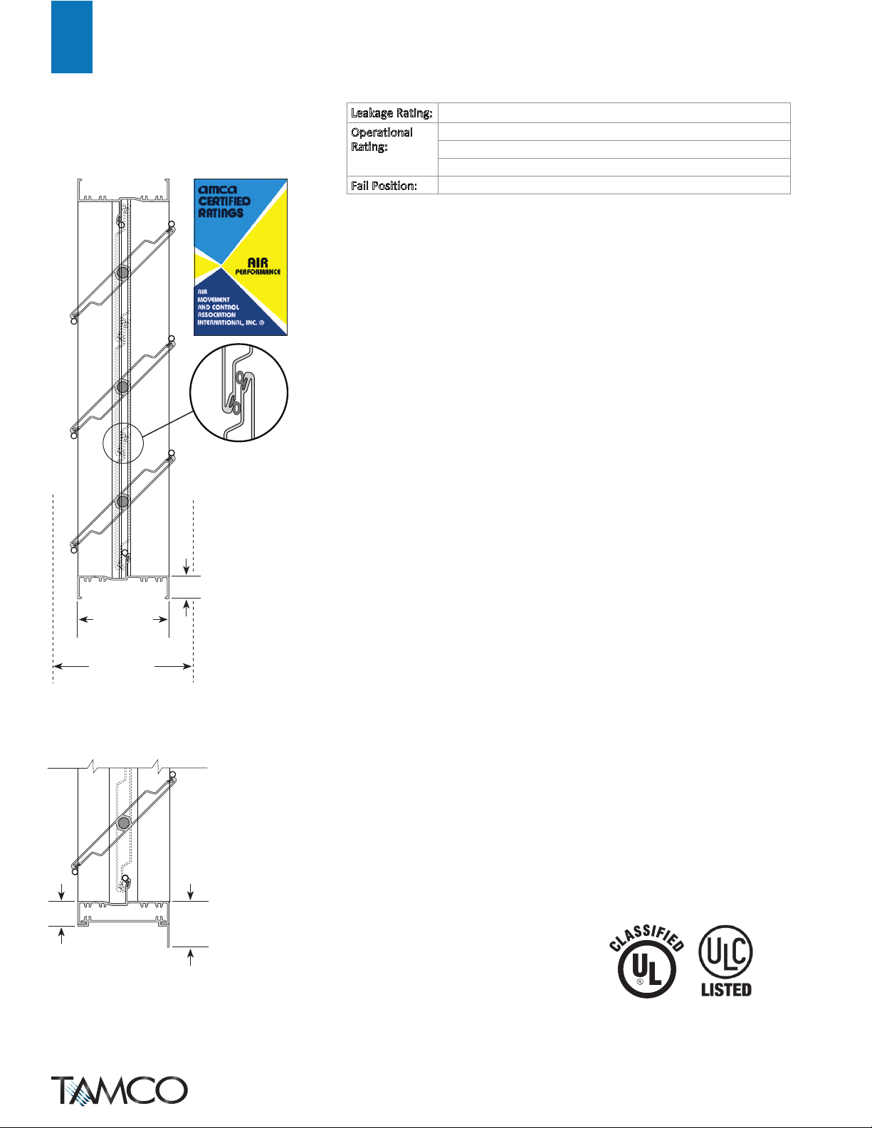
manuals.online logo
Brands
  1. Home
  2. •
  3. Brands
  4. •
  5. Tamco
  6. •
  7. Fire And Smoke Damper
  8. •
  9. Tamco 1000 SM Series User manual

Tamco 1000 SM Series User manual

6.4"
162.6 mm
blades fully open
4"
101.6 mm
1"
25.4 mm
In Duct or
Flanged to Duct
Install Types
1.06"
27 mm 2"
50.8 mm
Extended Rear Flange
Install Type
TAMCO® Series 1000 SM meets the require-
ments for smoke dampers established by:
UL 555S/ULC-S112.1 File R16679
National Fire Protection Association:
NFPA Standards 80, 90A, 92, 101, 105
California State Fire Marshall Listing#:
3230-2116:0100
Leakage Rating: Class 1
Operational
Rating:
Airflow: 2000 fpm (10.2 m/s). Rated for airflow in either direction.
Temperature: 250°F (121°C)
Pressure: 4” w.g. (1 kPa) static pressure differential
Fail Position: Closed
STANDARD CONSTRUCTION:
1. Extruded aluminum (6063-T5) smoke damper frame is not less than 0.080” (2.03 mm) in
thickness. Damper frame is 4” (101.6 mm) deep x 1" (25.4 mm), with mounting flanges on both
sides of frame. Damper frame has a 2" (50.8 mm) mounting flange on the rear of the damper,
when ordered as Extended Rear Flange install type.
2. Blades are maximum 6” (152.4 mm) deep extruded aluminum (6063-T5) air-foil profiles. All
blades are symmetrically pivoted.
3. Blade and frame seals are specially designed and engineered extruded silicone. Seals are
secured in an integral slot within the aluminum extrusions. Blade and frame seals are
mechanically fastened to prevent shrinkage and movement over the life of the damper.
4. Bearings are composed of a bronze oilite inner bearing - fixed around a 7/16” (11.11 mm)
aluminum hexagon blade pivot pin - rotating within a bronze oilite outer bearing inserted in
the frame.
5. The 7/16” (11.11 mm) hexagonal drive rod, U-bolt fastener, and hexagonal retaining nuts are
zinc-plated steel. These provide a positive connection to blades and linkage.
6. Aluminum and corrosion-resistant zinc-plated steel linkage hardware is installed in the frame
side, complete with cup-point trunnion screws for a slip-proof grip.
7. Smoke dampers are designed for operation in temperatures ranging from -40°F (-40°C) to
250°F (121°C).
8. Smoke dampers are custom made to required size, without blanking off free area.
9. Smoke dampers are available with parallel blade action.
CONSTRUCTION OPTIONS:
For each option listed, replace the lines above with their corresponding lines below.
MR - MOISTURE RESISTANCE OPTION:
1. Extruded aluminum (6063-T5) smoke damper frame is not less than 0.080” (2.03 mm) in
thickness. Damper frame is 4” (101.6 mm) deep x 1” (25.4 mm), with mounting flanges on both
sides of frame. Damper frame has a 2” (50.8 mm) mounting flange on the rear of the damper,
when ordered as Extended Rear Flange install type. Frame is assembled using stainless steel
screws.
5. The
7/16” (11.11 mm) hexagonal drive rod, U-bolt fastener, and hexagonal retaining nuts are
stainless steel. These provide a positive connection to blades and linkage.
6. Aluminum and stainless steel linkage hardware is installed in the frame side, complete with
cup-point trunnion screws for a slip-proof grip.
SW - SALT WATER RESISTANCE OPTION:
1. Extruded aluminum (6063-T5) smoke damper frame is not less than 0.080” (2.03 mm) in
thickness. Damper frame is 4” (101.6 mm) deep x 1” (25.4 mm), with mounting flanges on both
sides of frame. Damper frame has a 2” (50.8 mm) mounting flange on the rear of the damper,
when ordered as Extended Rear Flange install type. Aluminum frame is clear anodized to a
minimum thickness of 0.7 mil (18 microns) deep. Frame is assembled using stainless steel screws.
2. Blades are maximum 6” (152.4 mm) deep extruded aluminum (6063-T5) air-foil profiles, clear
anodized to a minimum thickness of 0.7 mil (18 microns) deep. All blades are symmetrically pivoted.
5. The
7/16” (11.11 mm) hexagonal drive rod, U-bolt fastener, and hexagonal retaining nuts are
stainless steel. These provide a positive connection to blades and linkage.
6. Linkage hardware is installed in the frame side. All aluminum linkage hardware parts are clear
anodized. All non-aluminum linkage hardware parts are stainless steel. They are complete with
cup-point trunnion screws for slip-proof grip.
SUBMITTAL DATA |
Series 1000 SM
UL/ULC Approved Smoke Damper
1
TAMCO JUNE, 2016
www.tamcodampers.com
© T.A. Morrison & Co. Inc., 2016
VELOCITY VS. PRESSURE DROP
Pressure Drop (inches w.g.)
Face Velocity (fpm)
AMCA Figure 5.3
100 500 1,000 5,000 10,000
1.0
0.5
0.1
.03
.01
LEGEND:
12" x 12"
(305 mm x 305 mm)
36" x 36"
(915 mm x 915 mm)
12" x 48"
(305 mm x 1220 mm)
24" x 24"
(610 mm x 610 mm)
48" x 12"
(1220 mm x 305 mm)
INSTALLATION:
10. Smoke dampers may be mounted vertically (standing up/horizontal airflow) with blades
running horizontally, or mounted horizontally (lying down/vertical airflow).
11. Dampers are available in four install types: Installed In Duct, Flanged to Duct, Extended Rear
Flange, and Square to Round Transition. (See Install Types pages for details.)
12. Multi-section smoke dampers may require field assembly of sections.
13. Installation of dampers must be in accordance with TAMCO’s current UL/ULC Approved
Smoke Damper Installation Guidelines, provided with each smoke damper shipment.
(Printed installation guidelines are provided with each damper shipment, however all
technical information available on TAMCO’s web site at www.tamcodampers.com supersedes
information contained within printed versions.)
ACTUATORS:
14. UL 555S/ULC-S112.1 requires that all actuators for smoke dampers be factory mounted.
Approved actuators are Belimo and Honeywell.
15. Voltage: 24 vac, 120 vac, 230 vac, single phase.
16. Mounting: Internal or external actuator mounting. (All smoke dampers with internally
mounted actuators, will be mounted on a jackshaft. If actuator side of damper is to be
connected to duct work, smoke damper assembly will have to be installed in a sleeve.)
17. Options: Auxiliary switches.
18. Actuator quantity and location requirements are shown in, and must be in accordance with,
TAMCO UL/ULC Approved Smoke Damper Configurations.
38
SUBMITTAL DATA |
Series 1000 SM
UL/ULC Approved Smoke Damper
2
TAMCO® Series 1000 SM meets the require-
ments for smoke dampers established by:
UL 555S/ULC-S112.1 File R16679
National Fire Protection Association:
NFPA Standards 80, 90A, 92, 101, 105
California State Fire Marshall Listing#:
3230-2116:0100
MINIMUM OPENING SIZE:
11”w x 6”h (280 mm x 153 mm)
MAXIMUM SINGLE-SECTION OPENING SIZE:
36"w x 48"h (915 mm x 1220 mm)
MAXIMUM MULTI-SECTION OPENING SIZES:
144”w x 96”h (3658 mm x 2438 mm)
288”w x 48”h (7316 mm x 1220 mm)
PERFORMANCE DATA |
Series 1000 SM
UL/ULC Approved Smoke Damper
FIG. 5.3
Test damper is fully ducted with a 5 diameter duct run
upstream, and a 6 diameter duct run downstream.
Pressure drop values are based on Flanged to Duct install type.
Pressure drop will be greater for In Duct install type dampers.
TAMCO JUNE, 2016
www.tamcodampers.com
© T.A. Morrison & Co. Inc., 2016
T.A. Morrison & Co. Inc. certifies that
the TAMCO Series 1000 SM UL/ULC
Approved Smoke Damper shown
herein is licensed to bear the AMCA
Seal. The ratings shown are based on
tests and procedures performed in
accordance with AMCA Publication 511
and comply with the requirements of
the AMCA Certified Ratings Program.
The AMCA Certified Ratings Seal
applies to air performance ratings.
>Always provide opening width and height dimensions, when ordering.
>Width dimension is always parallel to blades.
>Height dimension is always perpendicular to blades.
INSTALL TYPES |
Series 1000 SM
UL/ULC Approved Smoke Damper
FLANGED TO DUCT TYPE
&
>Finished damper O.D. is 2" (50.8 mm) greater
than opening width and height dimensions.
MINIMUM SECTION SIZE:
11”w x 6”h (280 mm x 153 mm)
MAXIMUM SECTION SIZE:
12 ft² (1.1 m²)
36”w x 48”h (915 mm x 1220 mm)
EXTERNAL ACTUATOR
Both front and rear flanges can be
mounted to opening surfaces.
INTERNAL ACTUATOR
Only rear flange can be mounted
to opening surface.
EXTENDED REAR FLANGE TYPE
&
>Finished damper O.D. is 4" (101.6 mm) greater
than opening width and height dimensions.
MINIMUM SECTION SIZE:
11”w x 6”h (280 mm x 153 mm)
MAXIMUM SECTION SIZE:
12 ft² (1.1 m²)
36”w x 48”h (915 mm x 1220 mm)
>Extended Rear Flange install type dampers are
not designed so that the front of the damper
may be inserted into an opening, as the side
frame members extend to the full height of the
rear flange.
EXTERNAL ACTUATOR
Both front and rear flanges can be
mounted to opening surfaces.
INTERNAL ACTUATOR
Only rear flange can be mounted
to opening surface.
INSTALLED IN DUCT TYPE
&
>Finished damper O.D. is ¼" (6.4 mm) less than
opening width and height dimensions.
MINIMUM SECTION SIZE:
11”w x 6”h (280 mm x 153 mm)
MAXIMUM SECTION SIZE:
12 ft² (1.1 m²)
36”w x 48”h (915 mm x 1220 mm)
INTERNAL ACTUATOR
Must be inserted in a sleeve,
or opening.
433
TAMCO JUNE, 2016
www.tamcodampers.com
© T.A. Morrison & Co. Inc., 2016
EXTERNAL ACTUATOR ONLY
SQUARE TO ROUND TRANSITION
&
>Always provide duct diameter dimension
when ordering.
>If using TAMCO Connect software to submit
orders, enter diameter dimension in both the
width and height fields.
>Transition pieces are a minimum of 18 ga. galva-
nized steel for Series 1000 SM smoke dampers
when ordered with no option.
>Transition pieces are 304 stainless steel, when
Series 1000 SM smoke dampers are ordered
with the MR or SW Options.
>Transition pieces and damper are sealed
together.
>Dampers are built 4" (102 mm) larger than
specified duct diameter. (Dampers are fabri-
cated square.)
>Finished transition diameter is ¼" (6.35 mm)
less than specified duct diameter, providing
clearance for mating duct which slides over
round transition. This ensures free movement
of damper blades.
MINIMUM DUCT DIAMETER:
9” (229 mm)
MAXIMUM DUCT DIAMETER:
58” (1474 mm)
MAXIMUM SECTION SIZE:
12 ft² (1.1 m²)
MAXIMUM FINISHED OD:
62”w x 62”h (1575 mm x 1575 mm)
INSTALL TYPES |
Series 1000 SM
UL/ULC Approved Smoke Damper
13"
(331 mm)
¼"
(6.35 mm)
less than
specied
4"
(102 mm)
1½"
(38 mm)
3"
(76 mm)
Joiner
Item# 7 S10080080
180.000 X 120.000 - Series1000 SM PARALLEL
PO# 123456 FLANGEDTO
Project ANYTOWN CITY HALL
Tag OAS 1EA
Batch111023 Shelf#24
PBJumper 1 - 5.625 Jumper
BladeSize 56.9896 GREY PARALLEL(E) 23F
LEFT
MILLBOTH
1.5 [69000] DRIVE
S10080080
BATCH# 111023
Shelf# 24
Item# 7
Section# 4
Item# 7 S10080080
180.000 X 120.000 - Series1000 SM PARALLEL
PO# 123456 FLANGEDTO
Project ANYTOWN CITY HALL
Tag OAS 1EA
Batch111023 Shelf#21
PBJumper 1 - 5.625 Jumper
BladeSize 56.9896 GREY PARALLEL(E) 23F
LEFT
MILLBOTH
1.5 [69000] DRIVE
S10080080
BATCH# 111023
Shelf# 21
Item# 7
Section# 1
Item# 7 S10080080
180.000 X 120.000 - Series1000 SM PARALLEL
PO# 123456 FLANGEDTO
Project ANYTOWN CITY HALL
Tag OAS 1EA
Batch111023 Shelf#26
PBJumper 1 - 5.625 Jumper
BladeSize 56.9896 GREY PARALLEL(E) 23F
RIGHT
MILLBOTH
1.5 [69000] DRIVE
S10080080
BATCH# 111023
Shelf# 26
Item# 7
Section# 6
Item# 7 S10080080
180.000 X 120.000 - Series1000 SM PARALLEL
PO# 123456 FLANGEDTO
Project ANYTOWN CITY HALL
Tag OAS 1EA
Batch111023 Shelf#23
PBJumper 1 - 5.625 Jumper
BladeSize 56.9896 GREY PARALLEL(E) 23F
RIGHT
MILLBOTH
1.5 [69000] DRIVE
S10080080
BATCH# 111023
Shelf# 23
Item# 7
Section# 3
1"
(25 mm)
2"
(51 mm)
4" - 6"
(102 mm - 153 mm)
58"
(1474 mm)
Maximum duct diameter
9"
(229 mm)
Minimum duct diameter
62"
(1575 mm)
Square maximum
Transition attaches to damper frame or
sleeve with minimum #8 sms screws,
¼” bolts, 3/16” rivets, or welds.
Linkage extends up to
15/16” (33 mm) beyond
the outer edge of the
transition.
4
TAMCO JUNE, 2016
www.tamcodampers.com
© T.A. Morrison & Co. Inc., 2016

Other Tamco Fire And Smoke Damper manuals

Tamco AIR-IQ Instruction sheet

Tamco

Tamco AIR-IQ Instruction sheet

Tamco 7000 Series Instruction sheet

Tamco

Tamco 7000 Series Instruction sheet

Tamco 1000 SM Series Instruction sheet

Tamco

Tamco 1000 SM Series Instruction sheet

Tamco AIR-IQ2 Instruction sheet

Tamco

Tamco AIR-IQ2 Instruction sheet

Popular Fire And Smoke Damper manuals by other brands

Schako BSK-RPR Installation, mounting and operating instructions

Schako

Schako BSK-RPR Installation, mounting and operating instructions

Swegon Actionair CSS Series installation guide

Swegon

Swegon Actionair CSS Series installation guide

Greenheck FD Series Installation instruction supplement

Greenheck

Greenheck FD Series Installation instruction supplement

Greenheck FSD Series Installation, operation and maintenance manual

Greenheck

Greenheck FSD Series Installation, operation and maintenance manual

Mandik FDMD installation instructions

Mandik

Mandik FDMD installation instructions

BSB FSD-C Series quick start guide

BSB

BSB FSD-C Series quick start guide

EKOVENT EKO-SRB1 Installation, operating and maintenance instructions

EKOVENT

EKOVENT EKO-SRB1 Installation, operating and maintenance instructions

SIOX MIDI SMOKE 2 manual

SIOX

SIOX MIDI SMOKE 2 manual

Val-Matic FrostSafe Two-Way Damper Operation, maintenance and installation manual

Val-Matic

Val-Matic FrostSafe Two-Way Damper Operation, maintenance and installation manual

Advanced Air 2500 Series manual

Advanced Air

Advanced Air 2500 Series manual

Maico BSB VC Series Installation, Operating and Maintenance Instruction

Maico

Maico BSB VC Series Installation, Operating and Maintenance Instruction

aldes CF1 Installation, operation and maintenance manual

aldes

aldes CF1 Installation, operation and maintenance manual

klimaoprema FD product manual

klimaoprema

klimaoprema FD product manual

Ace FRT-G2 Operating and mounting instructions

Ace

Ace FRT-G2 Operating and mounting instructions

Carrier 48DK024 installation instructions

Carrier

Carrier 48DK024 installation instructions

mercor mcr WIP EI60S Operation and maintenance manual

mercor

mercor mcr WIP EI60S Operation and maintenance manual

actionair FG Series manual

actionair

actionair FG Series manual

System air PK-I-R-EI60S manual

System air

System air PK-I-R-EI60S manual

manuals.online logo
manuals.online logoBrands
  • About & Mission
  • Contact us
  • Privacy Policy
  • Terms and Conditions

Copyright 2025 Manuals.Online. All Rights Reserved.