Gira 0913 00 User manual

Wind sensor Standard
Order No. : 0913 00
Operating instructions
1 Safety instructions
Electrical equipment may only be installed and fitted by electrically skilled persons.
Serious injuries, fire or property damage possible. Please read and follow manual fully.
Danger of electric shock. Always disconnect before carrying out work on the devise or
load. At the same time, take into account all circuit breakers that supply dangerous
voltage to the device or load.
Danger of electric shock. Not suitable for controlling 24 V Venetian blind inserts. If there
is a fault, 230 V might enter the 24 V network.
These instructions are an integral part of the product, and must remain with the end
customer.
2 Device components
Figure 1
1/6
82523842 07.08.2014
Wind sensor Standard
Blind control system
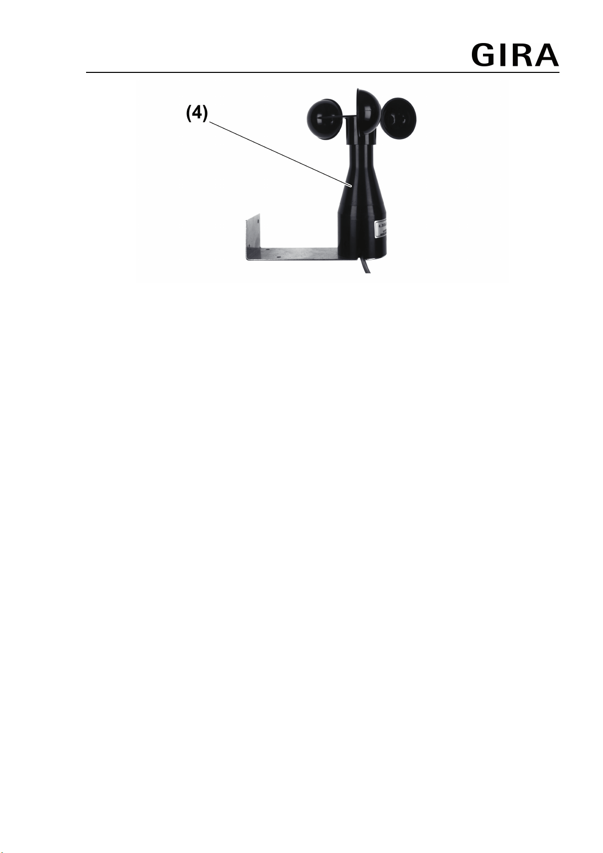
Figure 2
(1) Evaluation unit
(2) Test LED
(3) Housing lid screws
(4) Wind sensor
3 Function
Intended use
- The evaluation unit and wind sensor are used to protect a blind/shutter against destruction
due to excessively strong winds. The blind/shutter is moved to a safe end position and
locked there until the wind drops below the set wind speed value.
- The evaluation unit is operated together with a Venetian blind insert or binary inputs of the
KNX system.
- Surface-mounted devices for outdoor installation
Product characteristics
- Detection and evaluation of wind speeds
- 8 wind speeds can be set
- The wind alarm is triggered 15 seconds after the set wind speed threshold value is
exceeded
- Test operation for function testing
4 Information for electrically skilled persons
4.1 Fitting and electrical connection
Mounting and connecting the wind sensor
oMount the wind sensor on the roof or on the wall of a house. It must be attached at a
position suitable for wind speed measurement.
Do not mount it in the wind shadow and ensure mounting in the correct position (Figure 2).
oConnect wind sensor to the "+" and "-" terminals (7) of the evaluation unit. Use a shielded
cable for this. Recommendation: JY-ST-Y 2x0.6.
iSensor cables run SELV low voltages acc. to IEC 60364-4-41. When connecting the wind
encoder, ensure safe separation.
82523842 07.08.2014 2/6
Blind control system
Wind sensor Standard

Connecting the evaluation unit
DANGER!
Electrical shock when live parts are touched.
Electrical shocks can be fatal.
Before working on the device, disconnect all the corresponding miniature
circuit breakers. Cover up live parts in the working environment.
oRemove the housing lid of the evaluation unit by slackening the two screws (3).
oFor rear cable insertion, penetrate the rubber seal (6) and insert the cable (Figure 3).
Figure 3: Evaluation unit connection compartment
oFasten the device using two screws (10).
oInsert the cables into the connection housing and connect the according to the connection
diagram (Figure 4).
oIf multiple miniature circuit breakers supply dangerous voltages to the device or load,
couple the miniature circuit breakers or label them with a warning, to ensure release is
guaranteed.
iTerminals 1 and 2 serve as distributor terminals and are not connected inside the device.
They can be used, for example, for a heated wind sensor.
iThe distributor terminal (5) serves to connect the protective conductor.
82523842 07.08.2014 3/6
Blind control system
Wind sensor Standard

Figure 4: Connection diagram for connecting the evaluation unit to the Venetian blind controller
oThe evaluation unit has a relay with two potential-free NO contacts. To control the Venetian
blind insert (11) from the same conductor, place a bridge (12) between the relay input and
the conductor.
oCarry out commissioning (see Commissioning chapter).
oClose the housing lid of the evaluation unit.
iIf 230 V is present at extension input 2 of the insert (11), then the blind/shutter moves to
the top end position and cannot be operated, either manually or automatically.
iGlass break sensors may not be used jointly with the wind sensor. After there is a glass
break, the wind alarm function is locked and the Venetian blind or roller shutter does not
move to a safe end position.
4.2 Commissioning
DANGER!
Electrical shock when live parts are touched.
Electrical shocks can be fatal.
Before working on the device, cover up live parts in the working environment.
Setting the wind sensor switch in the evaluation unit
oOpen the housing lid of the evaluation unit.
oTurn the rotary switch to the (8) to the II position, factory setting (Figure 3).
Carrying out test operation
The rotary switch (9) specifies the wind speed at which the blind/shutter moves up or activates
the test operation.
In test operation, the function of the devices can be checked even at a low rotary speed.
oTurn the rotary switch (9) to the 1 or 2 position.
The test LED (2) lights up after a second.
oTurn the anemometer of the wind sensor.
The test LED flickers at the rotary speed of the anemometer.
Setting the wind speed threshold vale
oUsing the rotary switch (9), set the wind speed at which the blind/shutter is to move to the
protected end position (Figure 5). The setting is made in Beauforts Bft.
82523842 07.08.2014 4/6
Blind control system
Wind sensor Standard
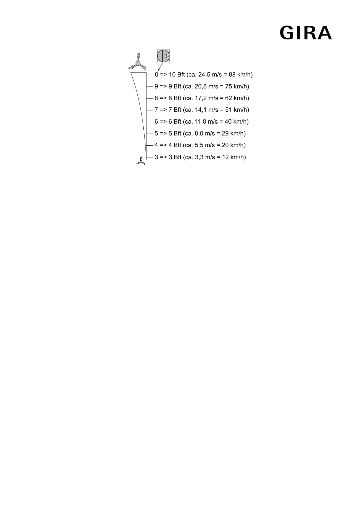
Figure 5: Wind speed setting
iIf there is a change between two wind speeds, the selected wind speed is applied after
max. 5 minutes. The wind speed is applied faster after short-term switch on of test
operation.
5 Appendix
5.1 Technical data
Rated voltage AC 230 V ~
Mains frequency 50 Hz
Degree of protection IP 55
Switching current max. 2 A
Contact type µ contact, potential-free NO contact
Connection
single stranded max. 4 mm²
Fine-wire max. 2.5 mm²
Finely stranded with conductor sleeve max. 1.5 mm²
Switch-on delay approx. 15 s
Switch-off delay approx. 15 min
Data according to EN 60730-1
Action 1.B
Degree of soiling 2
Meas. surge vol. 4000 V
SELV limit value AC 24 V ~
5.2 Warranty
The warranty is provided in accordance with statutory requirements via the specialist trade.
Please submit or send faulty devices postage paid together with an error description to your
responsible salesperson (specialist trade/installation company/electrical specialist trade). They
will forward the devices to the Gira Service Center.
82523842 07.08.2014 5/6
Blind control system
Wind sensor Standard

Gira
Giersiepen GmbH & Co. KG
Elektro-Installations-
Systeme
Industriegebiet Mermbach
Dahlienstraße
42477 Radevormwald
Postfach 12 20
42461 Radevormwald
Deutschland
Tel +49(0)21 95 - 602-0
Fax +49(0)21 95 - 602-191
www.gira.de
82523842 07.08.2014 6/6
Blind control system
Wind sensor Standard
Table of contents
Other Gira Control System manuals


Popular Control System manuals by other brands


Next Wave Automation
Next Wave Automation Digital Duplicator manual

Lectrotab
Lectrotab SETR-50 quick start guide

Pentair
Pentair EASYTOUCH PL4 installation guide

Bosch
Bosch rexroth HS5E instruction manual

IAI
IAI RCON-LC instruction manual

BST
BST eltromat EKR 1500 Translation of the original operating manual


