Gira 2605 Series User manual

Operating Instructions
Keypad
2605 ..

2
Contents
Device description .............................................................4
Device presentation ...........................................................5
Areas of application ...........................................................6
Operation ...........................................................................8
Acknowledgement signals ............................................... 10
Start-up sequence ............................................................ 11
Connection terminals .......................................................12
Installation ...................................................................... 13
What is an administrator, a user? ..................................... 14
Creating first administrator............................................... 15
Creating user for relay 1 ................................................... 16
Creating user for relay 2 ................................................... 17
Create a further administrator ..........................................18
Changing admin/user PIN................................................. 19
Deleting user.................................................................... 20
Deleting administrator......................................................21
Switching button illumination on/off ............................... 22
Switching acknowledgement tones on/off....................... 23
Setting switching time of relays ....................................... 24
Resetting to factory settings-selection of operating mode 25
Keypad in door communication system............................ 27
Connection to door communication system ..................... 28
Assignment of user - specific switching actuator/
door opener ..................................................................... 30
Assignment of user-group switching actuator/
door opener ..................................................................... 31

3
Assigning function button "F" to a switching actuator ......32
Assigning bell button to a home station ...........................33
Specifically assigning bell button to a home station .........34
Assigning bell button to a switching actuator................... 35
Specifically assigning bell button to a switching
actuator ........................................................................... 36
Relays / actuators – what switches when? ....................... 37
5 rules for selecting the correct mode .............................. 38
Assigning mode to an individual user............................... 39
Assigning mode to a user group ......................................40
Examples
Example 1: Start-up stand-alone function......................... 41
Example 2: Start-up multi-family house with
door communication system ............................................43
Example 3: Start-up single-family house with
door communication system ............................................47
Example 4: Integrating in door communication
system without speech function....................................... 50
Removal alarm .................................................................51
Table for start-up documentation ..................................... 52
Procedure with loss of admin PIN .................................... 53
Technical data ................................................................. 54
Warranty ......................................................................... 55

4
Device description
The keypad provides convenient and secure access control
for inside and outside areas. The keypad opens the door
when a personal code is entered. Capacitive switching tech-
nology enables operation by a light touch of the finger. The
keypad can be used as a stand-alone function, e.g. at individ-
ual doors or gates. It can also be integrated into the Gira door
communication system. No additional control components
are required here.
Easy start-up without a PC or programming software is pos-
sible via direct configuration at the device.
The two integrated zero-voltage two-way switch relays can
be assigned to different codes. Thus it is possible to carry out
two different switching processes, e.g. code 1 for door open-
ing and code 2 for switching the outside light via a remote-
control switch. The keypad can manage up to 255 codes
(incl. admin code and release code).
The keypad is installed indoors (IP 20) in conjunction with
System 55 cover frames and outdoors (IP 44) with TX_44
cover frames.
5
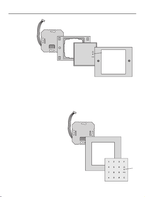
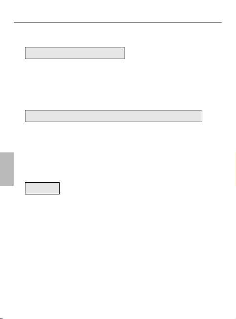
Device presentation
5
1
2
3
4
123F
456
789
0C
#
*
1
2
3
4
6
5
System 55
1 Connection cable for door
communication system
2 Flush-mounted insert
(keypad)
3 System 55 cover frame
(not in scope of supply)
4Keypad
5 Status LED
TX_44
1 Connection cable for door
communication system
2 Flush-mounted insert (keypad)
3 TX_44 cover frame, bottom
section (not included in scope
of supply)
4Keypad
5 Status LED
6 TX_44 cover frame top section
(not in scope of supply)

6
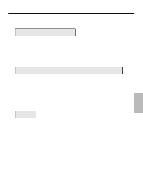
Areas of application
Use as individual device
In this case the existing zero-voltage relay contacts within
the flush-mounted insert are used, e.g. for a door opener
with own power supply.
iUse as individual device not in
safety-relevant areas
Not recommended for opening of outside doors especially
in safety-relevant areas, as door may be opened with expan-
sion of keypad via bridging of open contacts.
2
123F
456
789
0C
#
*
2
2
1
2
4
3
1Keypad
2 Door opener
3Powersupply
24 V DC
4Powersupply
of door opener

7
Use in door communication system
The keypad can be connected to the door communication
system via the enclosed connection cable. Thus the keypad
can control e.g. the door opener contact of the control device
or can trigger the switching action of a switching actuator.
In addition, further home stations can be specifically
selected.
iProtecting control device from unauthorised
access
In safety-relevant areas the control device should be
securely installed (locked) to prevent unauthorised access.
2
2
2
1
2
34
123F
456
789
0C
#
*
1Hands-freefeature
surface-mounted
home station
2 Flush-mounted
door station with
keypad
3 Audio control
device
4 Door opener
8
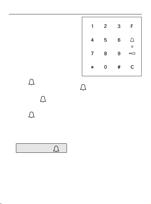
Operation
Button F - switching
Pressing the button "F" controls
the assigned switching actua-
tor.
Button C - correction
Button "C" deletes an incorrect
entry. The complete button
combination must then be re-
entered.
Button - triggering a door call
In smaller buildings the button can be used as a call
button.
If the button is pressed a door call is triggered at the
assigned home station.
Button - calling a specific home station
In buildings with several home stations, assigned home sta-
tions can be specifically called. For this purpose every home
station receives its own user ID. The home station is called
via the following button combinations:
User ID

9
Button - open door
The door is opened via the following button combinations:
In operating mode "small buildings":
In operating mode "large buildings" (see Page 25):
User PIN
User ID *User PIN
iAcknowledgement tones can be switched off
Acknowledgement tones occurring during operation can be
switched off (see Page 23).

10
Acknowledgement signals
The keypad generates different acknowledgement signals
during operation and start-up:
Positive acknowledgement signal
✓The keypad generates a long acknowledgement tone, the
LED simultaneously lights up green.
Negative acknowledgement signal
✓The keypad generates 3 short acknowledgement tones,
the LED simultaneously lights up red.
Administrator mode activated
✓The LED lights up orange.
In door communication system:
Programming mode activated
✓The keypad generates a short acknowledgement signal,
the LED flashes orange.
Programming mode terminated
✓The keypad generates a short acknowledgement tone, the
LED is off.
iAcknowledgement signal off
If the acknowledgement tone is switched off (see Page 23),
there are no more acknowledgement tones. The acknowl-
edgement signals then occur solely via the LED.
11
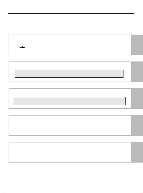
Start-up sequence
For start-up the keypad, the following steps must be imple-
mented in the order shown below:
I. Install keypad (from Page 12)
LED flashes green I
II. Create first administrator (Page 15)
II
III. Create user for relays 1/2 (from Page 16)
III
IV. Carry out configurations to keypad
(from Page 19) IV
V. Use in door communication system
Assigning door opener/switching actuators (from
p. 27)
V
* 3 * Admin IDNew *Admin PINNew #
*1/2 *User IDNew *User PINNew #
12
I
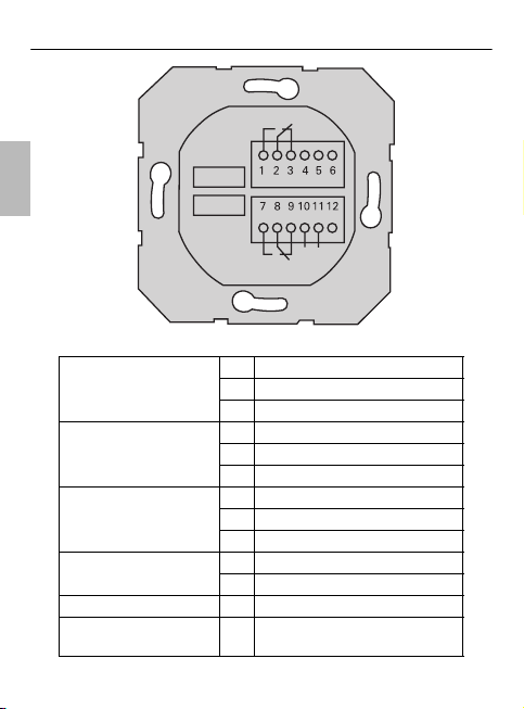
Connection terminals
Relay 1
1 Relay 1 N.O. (NO contact)
2 Relay 1 COM
3 Relay 1 N.C. (NC contact)
Service
4 not used
5 not used
6GND
Relay 2
7 Relay 2 N.O. (NO contact)
8 Relay 2 COM
9 Relay 2 N.C. (NC contact)
Power supply 10 GND
11 + 24 V DC
12 not used
Door communication 13 6-pole slot
door communication system
13
13
+24V DC
GND

13
I
Installation
The keypad is connected via both detachable terminal strips
and mounted in a 58 mm flush-mounted box.
1. Pull off required terminal strip and connect according to
terminal figuration.
2. Attach terminal strip to the flush-mounted insert again.
3. Install flush-mounted insert into flush-mounted box.
4. Install cover frame and attach cover plate of the keypad.
✓10 seconds after operating voltage is applied, the LED of
the keypad flashes green.
5. Start-up the keypad:
• first create an administrator (Page 15),
• then create the user (from Page 16),
• then if necessary assign switching actuator functions
or door opener functions (from Page 30).
Attention
Installation and mounting of electrical devices may only be
carried out by a qualified electrician.

14
II
What is an administrator, a user?
For starting up, an administrator must be created. Users are
created for operation.
Administrator
An administrator always consists of an admin ID and an
admin PIN
• Admin ID: 1 to 6-digit
• Admin PIN: 1 to 32-digit (for configuration of
keypad)
User
A user consists of a user ID and a user PIN
• User ID: 1 to 6-digit (for door call functions)
• User PIN: 1 to 32-digit (for door opening
functions or switching actions).
iInformation about IDs and PINs
The allocation of identical IDs is not possible. If an adminis-
trator receives ID 1, there cannot be a user with the ID 1.
The allocation of identical PINs is only possible in operating
mode "large buildings". Further information about operating
modes "small buildings" / "large buildings" on p. 26

15
II
Creating first administrator
Before first start-up, an administrator must be created. If no
administrator has been created, the LED of the keypad
flashes green.
Create administrator:
✓LED flashes green.
1. Create new administrator:
✓The keypad generates a positive acknowledgement sig-
nal:
An administrator was created successfully.
The keypad is now in administrator mode.
2. Enter administrator with ID and PIN into the table on
Page 52.
iAdmin ID and admin PIN
Admin ID and admin PIN cannot be used for switching
actions, e.g. for opening of a door.
* 3 * Admin IDNew *Admin PINNew #
iCorrect operating mode selected?
Upon delivery the operating mode "small buildings" is pre-
set. This means that identical PINs cannot be assigned. Fur-
ther information about operating modes "small buildings" /
"large buildings" on Page 26.
16
III
Creating user for relay 1
The following describes how a user is created for relay 1.
1. Start administrator mode (if not already active):
✓After a positive acknowledgement signal the keypad is in
administrator mode.
✓A negative acknowledgement signal indicates an incor-
rect entry (e.g. of the admin PIN).
2. Create user for relay 1:
✓The keypad generates a positive acknowledgement sig-
nal:
The user was created successfully.
✓Further users can now be created.
3. Administrator mode ends after 15 seconds automatically
or after entering:
4. Enter user with ID and PIN into the table on Page 52.
* 0 * Admin PIN #
* 1 * User IDNew *User PINNew #
* 0 #
17
III
Creating user for relay 2
The following describes how a user is created for relay 2.
1. Start administrator mode (if not already active):
✓After a positive acknowledgement signal the keypad is in
administrator mode.
✓A negative acknowledgement signal indicates an incor-
rect entry (e.g. of the admin PIN).
2. Create user for relay 2:
✓The keypad generates a positive acknowledgement sig-
nal:
The user was created successfully.
✓Further users can now be created.
3. Administrator mode ends after 15 seconds automatically
or after entering:
4. Enter user with ID and PIN into the table on Page 52.
* 0 * Admin PIN #
* 2 * User IDNew *User PINNew #
* 0 #
18
III
Create a further administrator
An administrator is created as follows:
1. Start administrator mode (if not already active):
✓After a positive acknowledgement signal the keypad is in
administrator mode.
✓A negative acknowledgement signal indicates an incor-
rect entry (e.g. of the admin PIN).
2. Create new administrator:
✓The keypad generates a positive acknowledgement
signal:
The administrator was created successfully.
3. Administrator mode ends after 15 seconds automatically
or after entering:
4. Enter administrator with ID and PIN into the table on
Page 52.
* 0 * Admin PIN #
* 3 * Admin IDNew *Admin PINNew #
* 0 #

19
IV
Changing admin/user PIN
The corresponding PIN is changed when the user or admin-
istrator is assigned a new PIN:
1. Start administrator mode (if not already active):
✓After a positive acknowledgement signal the keypad is in
administrator mode.
✓A negative acknowledgement signal indicates an incor-
rect entry (e.g. of the admin PIN).
2. Change user PIN:
Change admin PIN:
✓The keypad generates a positive acknowledgement
signal:
The PIN has been successfully set.
✓The keypad generates a negative acknowledgement sig-
nal:
Invalid ID entered.
3. Administrator mode ends after 15 seconds automatically
or after entering:
* 0 * Admin PIN #
* 4 * User ID *User PINNew #
* 4 * Admin ID *Admin PINNew #
* 0 #

20
IV
Deleting user
A user is deleted as follows:
1. Start administrator mode (if not already active):
✓After a positive acknowledgement signal the keypad is in
administrator mode.
✓A negative acknowledgement signal indicates an incor-
rect entry (e.g. of the admin PIN).
2. Delete user:
✓The keypad generates a positive acknowledgement
signal:
The user was deleted successfully.
✓The keypad generates a negative acknowledgement
signal:
An incorrect user ID was entered.
✓Further users can now be deleted.
3. Administrator mode ends after 15 seconds automatically
or after entering:
4. Remove deleted users from the table on Page 52 .
* 0 * Admin PIN #
* 5 * User ID #
* 0 #
Table of contents


